I. Introduction to MM440 Series Inverter Operating Panel Functions
1.1 Overview of Operating Panels

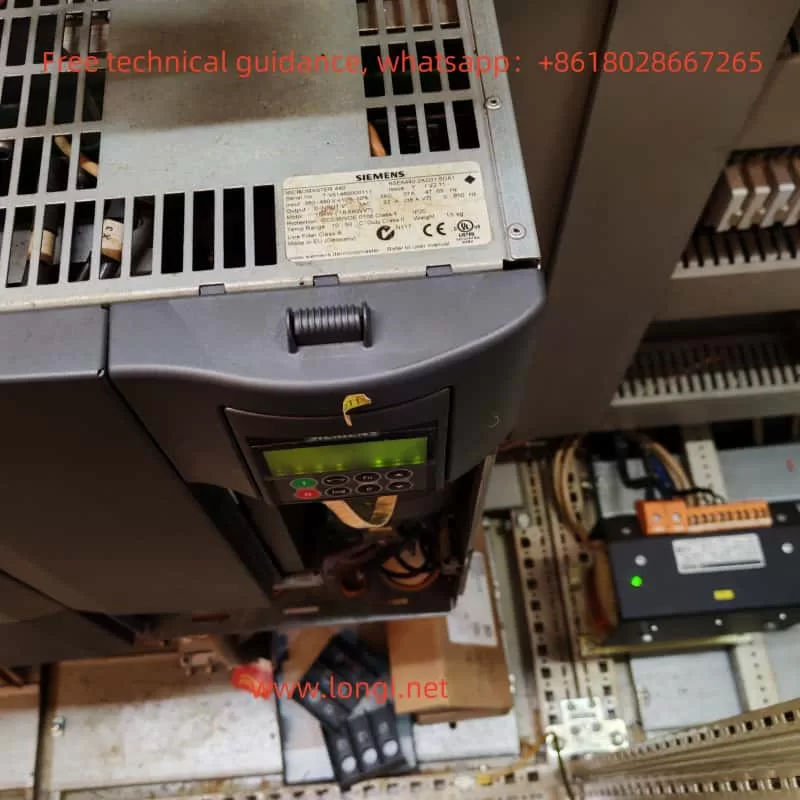
The Siemens MM440 series inverter is equipped with operating panels, including the Status Display Panel (SDP), Basic Operating Panel (BOP), and Advanced Operating Panel (AOP). These panels provide an intuitive interface for user interaction with the inverter, enabling monitoring, setting, and control of the inverter’s operation.
1.2 Setting Passwords and Parameter Levels
To prevent unauthorized changes, the MM440 inverter supports parameter locking and password protection. To set passwords and parameter levels, follow these steps:
- Enter Parameter Setting Mode: Use the BOP or AOP to press the “P” key to enter parameter setting mode.
- Select Password Parameter: Locate and set parameter P0012 (Unlocking of User-Defined Parameters) to your desired password.
- Lock Parameters: Set parameter P0011 (Locking of User-Defined Parameters) to 1 to enable password protection.
1.3 Restoring Factory Settings
To restore the inverter parameters to factory settings, follow these steps:
- Enter Parameter Setting Mode.
- Set P0010=30: Select the restore factory settings function.
- Set P0970=1: Confirm the execution of restoring factory settings.
1.4 Using BICO Functionality
The BICO (Binary Interconnect Connection) function allows users to program interconnections between internal signals and input/outputs of the inverter. To use the BICO function, follow these steps:
- Enter Parameter Setting Mode.
- Set Relevant BICO Parameters: For example, P0701 to P0708 are used to configure the functions of digital inputs, and P0731 to P0733 are used to configure the functions of digital outputs.
- Program Interconnection Logic: According to application requirements, use BICO control words and status words to program the desired interconnection logic.
II. Terminal Control and External Potentiometer Speed Regulation
2.1 Terminal Control
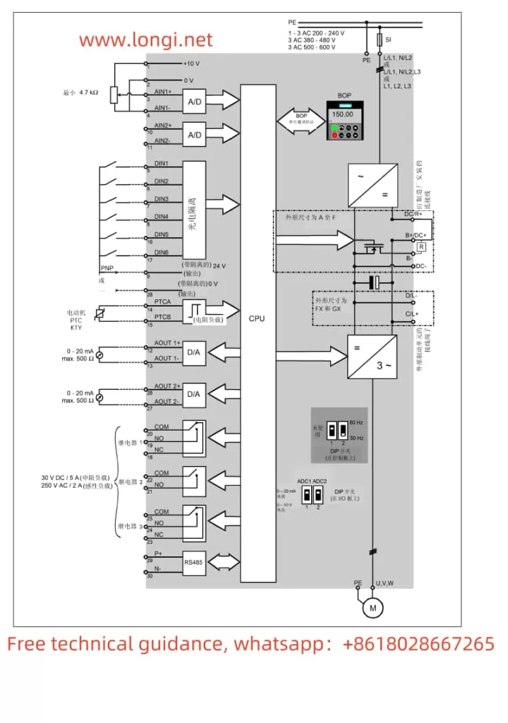
The MM440 inverter supports speed control via terminals. To achieve terminal control, follow these steps to set parameters and wiring:
- Set Command Source: Set parameter P0700 to 2 to select terminal control mode.
- Configure Digital Inputs: Configure parameters P0701 to P0708 as needed to specify the functions of each digital input (such as start, stop, direction control, etc.).
- Wiring: Connect external control signals (such as start and stop buttons) to the corresponding digital input terminals.
2.2 External Potentiometer Speed Regulation
An external potentiometer can be used to adjust the output frequency of the inverter, enabling speed regulation. The setup steps are as follows:
- Set Frequency Reference Source: Set parameter P1000 to 2 to select analog input as the frequency reference source.
- Configure Analog Input: Ensure that analog input AIN1 or AIN2 is correctly configured to receive a 0-10V or 0-20mA speed regulation signal.
- Wiring: Connect the output of the external potentiometer to the AIN1 or AIN2 terminal of the inverter, and ensure that the potentiometer is properly powered.

III. Meaning of A503 Warning and Solutions
3.1 Meaning of A503 Warning
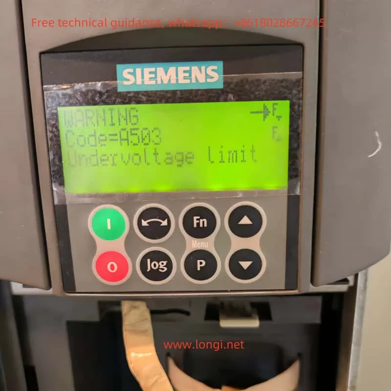
The A503 warning indicates that the inverter has detected undervoltage limitation, meaning that the DC link voltage is below the allowed minimum value. This can be caused by unstable supply voltage, input power failure, or internal inverter faults.
3.2 Solutions
- Check Supply Voltage: Ensure that the input supply voltage is within the allowed range and remains stable.
- Adjust Parameters:
- Increase the ramp-down time (P1121) to reduce voltage drops during braking.
- If the dynamic buffer function is enabled (P1240=2), adjust relevant parameters (such as P1243, P1245) to optimize performance.
- Check Inverter Internals: If the problem persists, it may be necessary to check the internal DC link and capacitors of the inverter for proper function.
3.3 Fault Codes and Meanings
The MM440 inverter has multiple fault codes that indicate different fault conditions. Here are some common fault codes and their meanings:
- F0001: Overcurrent, usually caused by motor or cable short circuits, mismatched motor power, etc.
- F0002: Overvoltage, possibly due to excessively high supply voltage or excessive regenerative energy generated during braking.
- F0003: Undervoltage, indicating that the input supply voltage is below the allowed range.
- F0004: Inverter overtemperature, usually caused by poor cooling or excessively high ambient temperature.
- F0011: Motor overtemperature, possibly due to motor overload or poor cooling.
3.4 Fault Solutions
Methods for resolving inverter faults typically include checking the supply voltage, motor and cable connections, cooling system, and internal components of the inverter. Specific steps should be taken based on the indications of the fault code.

IV. Conclusion
This article provides a detailed introduction to the operating panel functions, terminal control and external potentiometer speed regulation setup methods, as well as the meaning and solutions of the A503 warning for the Siemens MM440 series inverter. Additionally, it outlines common fault codes, their meanings, and solutions. With the guidance of this article, users can better understand and utilize the MM440 series inverter to ensure stable equipment operation.
