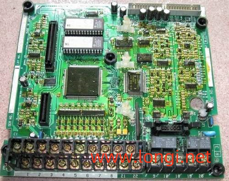
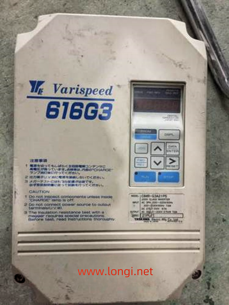
The power on display is normal. Start the operation, that is, jump “GF” fault, but it does not run or shows no signs of running. I quickly jumped over the ground fault. The “GF” fault at this time is equivalent to the “OC” fault of other frequency converters, and the fault is located in the inverter module or driving circuit. At the moment when the CPU sends the trigger pulse, it detects an abnormally large pressure drop in a certain IGBT tube and fails to open it normally during the arrival of the trigger pulse. In fact, during this time, the current transformer of the frequency converter did not detect the output current signal at all. At this point, the “GF” fault signal is fed back to the CPU by the module fault detection circuit of the driving circuit. (This fault action was determined by testing.)

Repair and inspection: Check the quality of the inverter block, especially the inspection of the trigger terminal cannot be ignored; Check the driving circuit, especially the filter capacitor of the driving power supply, and measure whether the driving voltage is normal, but whether there is a certain current driving ability.
- Jumping “GF” fault during operation is a fault reported by the current detection circuit. There are two aspects that need to be distinguished. On the one hand, it is a normal fault shutdown action, where the current transformer detects abnormal overcurrent and reports to the CPU to implement fault shutdown protection; On the one hand, the subsequent current signal processing circuit of the current transformer is faulty, such as the variable value of the resistor element, which causes the “GF” fault voltage setting point to drift, resulting in false alarm faults. The signal from the current transformer is processed through an operational amplifier, sent to the CPU for current display and fault alarm processing, and sent to a voltage comparator, reporting a “GF” fault. (Note: The subsequent circuit of this current transformer was not thoroughly investigated, but it was inferred from numerous fault phenomena and is for reference only.)
Repair and inspection: When it is confirmed to be a false alarm fault, it is not necessarily necessary to replace the motherboard for repair. Detailed inspection of the current transformer and its subsequent circuits should be able to repair it. - By the way, when an overcurrent fault is reported during operation for OL1, OL2, and OL3, it is detected by the current transformer and subsequent current signal processing circuit during operation. After sending the current signal to the CPU, it is judged, frequency reduced, and processed to report the overcurrent fault signal. For sudden abnormal overcurrent faults, module damage, or abnormal driving circuit faults, the driving circuit will directly feedback to the CPU, and the CPU will report an OC fault.

This suggests different treatments for undervoltage and overvoltage faults in other frequency converters. For undervoltage, after power on, it is detected and delayed for at least 5 seconds before reporting. Started 5 seconds ago and was able to run, but then experienced an undervoltage fault; For overvoltage faults, the fault will trip immediately after power on and operation is prohibited. It can be seen that designers attach greater importance to overvoltage faults than undervoltage faults. It can also be known that overvoltage faults pose greater harm to frequency converters than undervoltage faults do to frequency converters. And the handling of different fault alarms by designers can also be understood.
