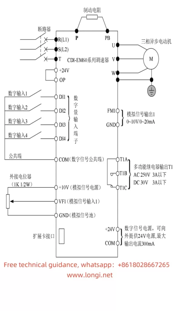
I. Introduction to Operation Panel Functions
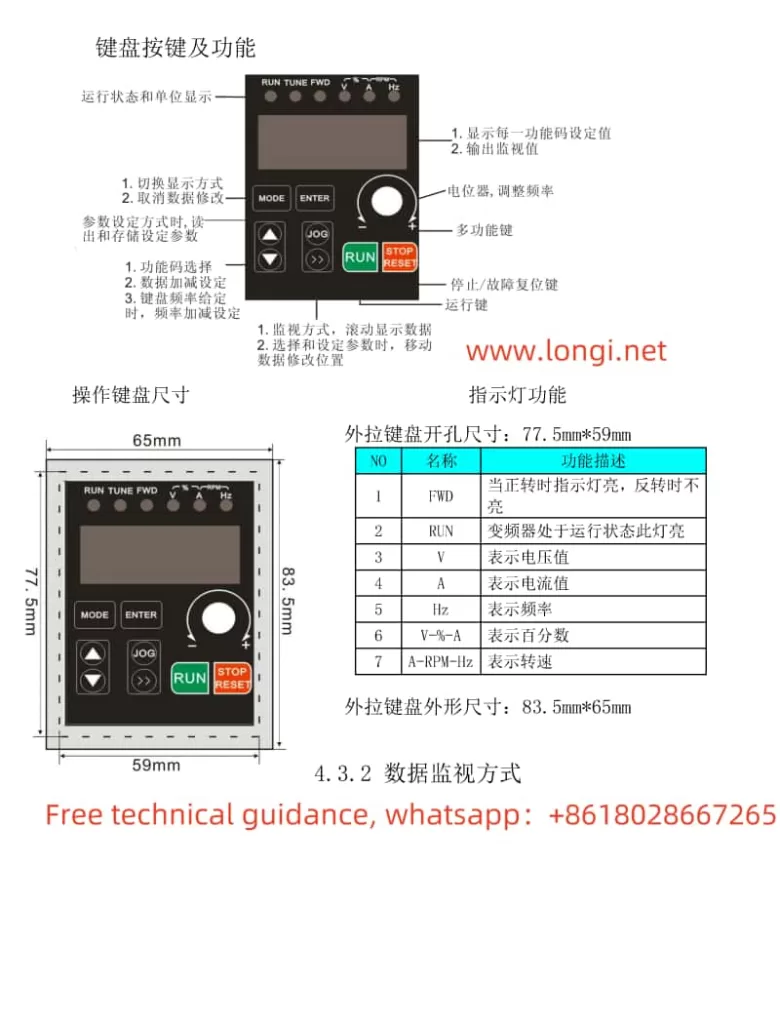
The Delixi Inverter CDI-EM60/CDI-EM61 series is equipped with an intuitive and user-friendly operation panel, enabling users to easily set and adjust parameters.

Key Components of the Operation Panel
- Display Screen: Displays various operation parameters, status indicators, and error messages.
- Function Keys:
- RUN: Starts the inverter.
- STOP: Stops the inverter.
- JOG: Enables jogging (inching) operation.
- PROG: Enters programming mode for parameter adjustment.
- ESC/RESET: Exits programming mode or resets errors.
- ▲/▼: Adjusts parameter values.
- ▶/◀: Navigates through menus.
Basic Operations
- Power On: Ensure the inverter is properly powered on.
- Navigation: Use the ▶/◀ keys to navigate through different menus and parameters.
- Value Adjustment: Use the ▲/▼ keys to adjust parameter values.
- Save & Exit: Press the ESC key to save changes and exit programming mode.
II. Using Simplified Internal Relay Programming Function
The Simplified Internal Relay Programming function allows users to perform basic logical operations using the inverter’s internal relays.
Steps to Configure
- Enter Programming Mode: Press the PROG key to enter programming mode.
- Navigate to Relay Control Parameters: Use the ▶/◀ keys to navigate to the relay control parameters (P3.2 group).
- Set Relay Logic:
- P3.2.00: Set the control logic for each relay (M1-M5).
- P3.2.01-P3.2.06: Configure the input conditions for each relay.
- P3.2.07-P3.2.11: Define the output actions for each relay.
- Set Delay Times:
- P3.2.12-P3.2.16: Set the on-delay times for each relay.
- P3.2.17-P3.2.21: Set the off-delay times for each relay.
- Save Settings: Press the ESC key to save changes and exit programming mode.

III. Using Internal Timer Function
The Internal Timer function provides users with timing control capabilities.
Steps to Configure
- Enter Programming Mode: Press the PROG key to enter programming mode.
- Navigate to Timer Control Parameters: Use the ▶/◀ keys to navigate to the timer control parameters (P3.2.22-P3.2.25).
- Set Timer Control:
- P3.2.23: Configure timer start/stop conditions.
- P3.2.24/P3.2.25: Set the timer duration for Timer 1 and Timer 2.
- Set Timer Units:
- P3.2.23: Select the time units (seconds, minutes, or hours).
- Save Settings: Press the ESC key to save changes and exit programming mode.
IV. Using Internal Calculation Module Function
The Internal Calculation Module function enables users to perform simple arithmetic operations and logical judgments.
Steps to Configure
- Enter Programming Mode: Press the PROG key to enter programming mode.
- Navigate to Calculation Module Parameters: Use the ▶/◀ keys to navigate to the calculation module parameters (P3.2.26-P3.2.39).
- Select Operation Type:
- P3.2.26: Choose the type of operation (addition, subtraction, multiplication, division, comparison, etc.).
- Set Input Addresses:
- P3.2.28/P3.2.29: Specify the input addresses (A and B) for the operation.
- Set Scaling Factors:
- P3.2.30/P3.2.33: Define the scaling factors for the operation results.
- Configure Output:
- Set the output address or action for the calculation result.
- Save Settings: Press the ESC key to save changes and exit programming mode.
V. Restoring Parameters to Factory Defaults
To restore the inverter parameters to their factory defaults, follow these steps:
- Enter Programming Mode: Press the PROG key to enter programming mode.
- Navigate to Parameter Initialization: Use the ▶/◀ keys to navigate to the parameter initialization parameter (P5.0.19).
- Select Initialization Option:
- Set P5.0.19 to “09” to restore factory parameters, excluding motor parameters, calibration parameters, and password parameters.
- Set P5.0.19 to “19” to restore factory parameters, excluding motor parameters and password parameters.
- Confirm Initialization: Press the RUN key to confirm the initialization process. The inverter will restart automatically.
- Exit Programming Mode: Press the ESC key to exit programming mode.
By following these guidelines, users can efficiently utilize the advanced features of the Delixi Inverter CDI-EM60/CDI-EM61 series, ensuring optimal performance and reliable operation.
