
Omron, a leading Japanese brand in the field of Programmable Logic Controllers (PLCs), holds a significant market share in mainland China. Given its widespread application in industrial control systems, understanding the maintenance of Omron PLCs, particularly their switching power supplies, is crucial for ensuring operational efficiency and minimizing downtime. This article delves into the maintenance process of Omron PLC switch power supplies, focusing on common faults, diagnosis, and repair methods.
The Importance of Switch Power Supplies in Omron PLCs
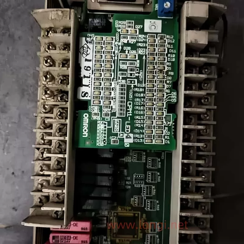
The switch power supply is a critical component of any PLC, including Omron models. It converts the incoming AC power into the DC voltage required to operate the PLC’s internal circuitry. A faulty power supply can lead to a variety of issues, ranging from the PLC not powering on at all to intermittent operation and potential damage to other components.
Common Faults in Omron PLC Switch Power Supplies
One of the most common issues encountered with Omron PLCs not displaying after being powered on is a faulty switch power supply. Fortunately, these power supplies are often relatively simple in design, making them easier to diagnose and repair. Based on extensive repair experience, there are three primary components that commonly fail:
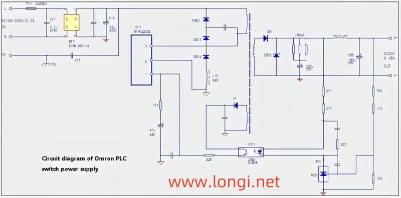
- F11 Fuse: This fuse is designed to protect the circuit from overcurrent situations. If the fuse blows, it indicates that there has been an excessive current draw, possibly due to a short circuit or component failure.
- IC11 Power Module: The power module is the heart of the switch power supply, responsible for converting AC to DC. It can fail due to age, overheating, or surge currents.
- C12 Electrolytic Capacitor: Often overlooked, the C12 capacitor plays a crucial role in stabilizing the power supply. Over time, the electrolyte inside the capacitor can evaporate, leading to a loss of capacity. This loss of capacity can cause surge currents that the power module cannot handle, leading to its failure.
Diagnosing and Repairing Omron PLC Switch Power Supplies
When faced with a non-responsive Omron PLC, the first step is to check the switch power supply. Here’s a step-by-step guide to diagnosing and repairing common faults:
- Visual Inspection: Start by visually inspecting the power supply for any signs of damage or burnout. Check the fuse (F11) to see if it has blown.
- Measure Component Values:
- Fuse (F11): Use a multimeter to check for continuity. If the fuse is open (no continuity), it needs to be replaced.
- Power Module (IC11): Measure the voltage across the module’s input and output terminals. If the module is faulty, you may find abnormal voltage readings or no voltage at all.
- Electrolytic Capacitor (C12): This is where many technicians make a mistake. Even if the capacitor looks normal and shows no signs of short-circuiting when measured in-circuit, it may have lost significant capacity. Remove the capacitor and measure its capacitance. A healthy capacitor should have a value close to its rated capacity. If it’s significantly lower, replace it.
- Repair and Replacement:
- Replace any blown fuses (F11) with a fuse of the same rating.
- If the power module (IC11) is faulty, replace it with an exact match. Ensure that the new module’s specifications (such as voltage, current, and frequency) match the original.
- When replacing the electrolytic capacitor (C12), choose a high-quality replacement with the same or higher capacitance and voltage rating. Be sure to install it away from heat sources to prevent future capacity loss.
- Testing: After making repairs, test the power supply without load first. If it powers on without issue, gradually add load to ensure stability. Listen for any abnormal sounds, such as a “snap,” which may indicate a component failure.
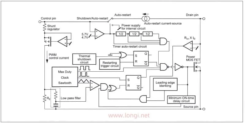
Understanding the IC11 MIP0223SC Power Module
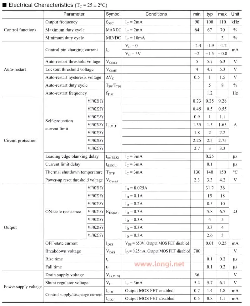
To effectively maintain the switch power supply, it’s essential to understand the key components, especially the IC11 MIP0223SC power module. While a detailed understanding of all the parameters and unit circuits is not necessary, familiarity with the module’s basic functions and pin connections is crucial. Refer to the schematic data table for key parameters such as power supply voltage, oscillation frequency, working current, and power capacity. This information will guide you in troubleshooting and ensuring compatibility when replacing components.
Conclusion
Maintaining Omron PLC switch power supplies doesn’t have to be a daunting task. By understanding the common faults, performing thorough diagnostics, and using high-quality replacement components, you can keep your PLCs running smoothly and minimize downtime. Remember, the key to successful maintenance is not just replacing faulty parts but also identifying the root causes of failures, such as the loss of capacity in electrolytic capacitors, and addressing them proactively. With this guide, you’ll be well-equipped to handle any issues that arise with Omron PLC switch power supplies, ensuring the reliability and longevity of your industrial control systems.