
Repairing a frequency converter, especially one that reports a stubborn ground fault (GF), can be a challenging and frustrating task. Recently, I encountered such an issue with a Yaskawa 616G3 55kW frequency converter. Despite the common advice to replace the board, I delved deeper into the problem, determined to find a logical solution. This article outlines the step-by-step process I followed to diagnose and repair the GF fault without replacing any major components.
Initial Diagnosis and Background
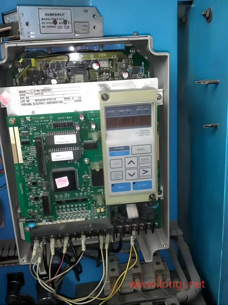
The Yaskawa 616G3 frequency converter had been out of service for two to three years before it arrived at our repair department. Upon inspection, we found that two of the three-phase power input rectifier modules and two of the six inverter IGBT modules were damaged. The driver board had also suffered some component damage due to the module failure.
The GF fault typically indicates an issue with the drive circuit or the IGBT module itself, especially during the initial startup stage when the three-phase output voltage has not yet been established. Understanding the structure of the protection circuit helped narrow down the potential causes. The GF and OC (load-side short circuit) fault signals are fed directly to the CPU by the protection circuit of the driving circuit board.
Driver and Protection Circuits Inspection
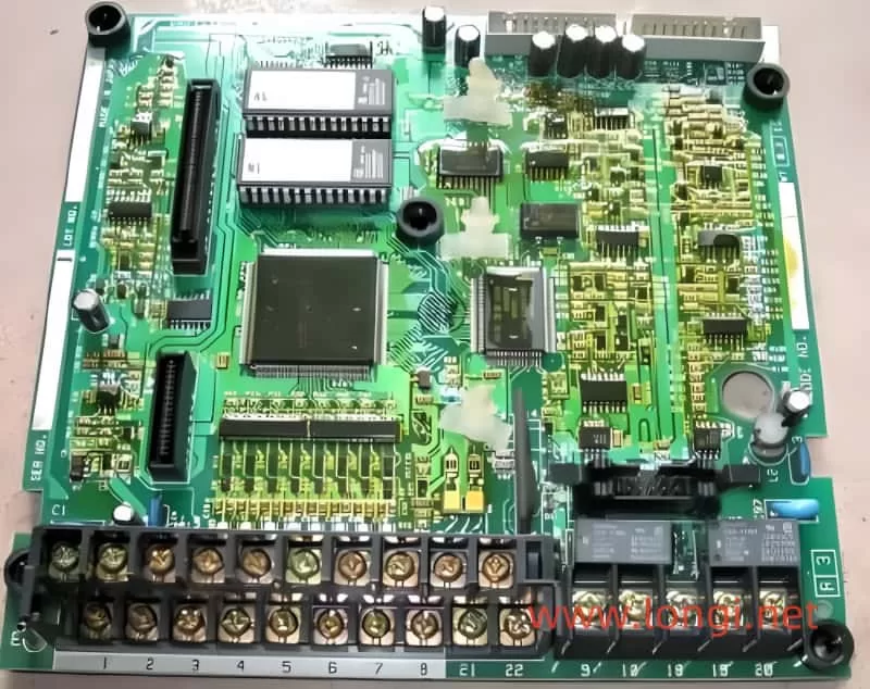
The driver circuit of the Yaskawa frequency converter includes six pulse signals from the CPU, isolated and amplified by six TLP250 ICs, and sent to the IGBT modules. Additionally, six TLP750 ICs form a module fault protection circuit, reporting GF and OC signals to the CPU. There are also three 2501 optocouplers responsible for detecting fuse status.
After disconnecting the driver board and CPU motherboard, I replaced the damaged components in the power amplifier circuit. The switch power supply and motherboard appeared to be functioning correctly. I manually cleared other potential faults, such as overvoltage, undervoltage, overheating, and fan issues, to ensure the drive circuit could output normal excitation pulses.
Addressing the FU Fault
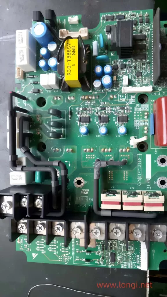
During the initial tests, the circuit reported an FU (fuse) fault. After inspecting the relevant optocoupler components and circuit components, I found that the copper foil strip of the N lead was broken due to mold. This caused the fuse detection circuit to assume the fuse was broken. I repaired the moldy copper foil strip and retested the circuit, which resolved the FU fault.
Further Investigation and Component Replacement
With the FU fault resolved, I pressed the RUN button on the operation panel and measured the six pulses output by the drive circuit, all of which were normal. However, the GF fault persisted. I re-inspected the driver board, measuring all circuit components and short-circuiting the GF fault feedback optocoupler, but the GF fault still tripped.
Further investigation revealed a poor contact between a diode in the IGBT voltage drop detection circuit and the copper foil strip. I also found that the positive voltage of the W-phase transistor driver pulse was low, indicating an issue with the driver IC. After replacing the faulty A3320 IC, the output pulse amplitude returned to normal.
The Stubborn GF Fault
Despite repairing the identified issues, the GF fault still occurred during startup. I used the fault zone cutting method to narrow down the fault range, eventually finding that the IGBT driver circuit (protection circuit) of the U-arm was prone to reporting the GF fault. A diode with a poor contact was identified and replaced.
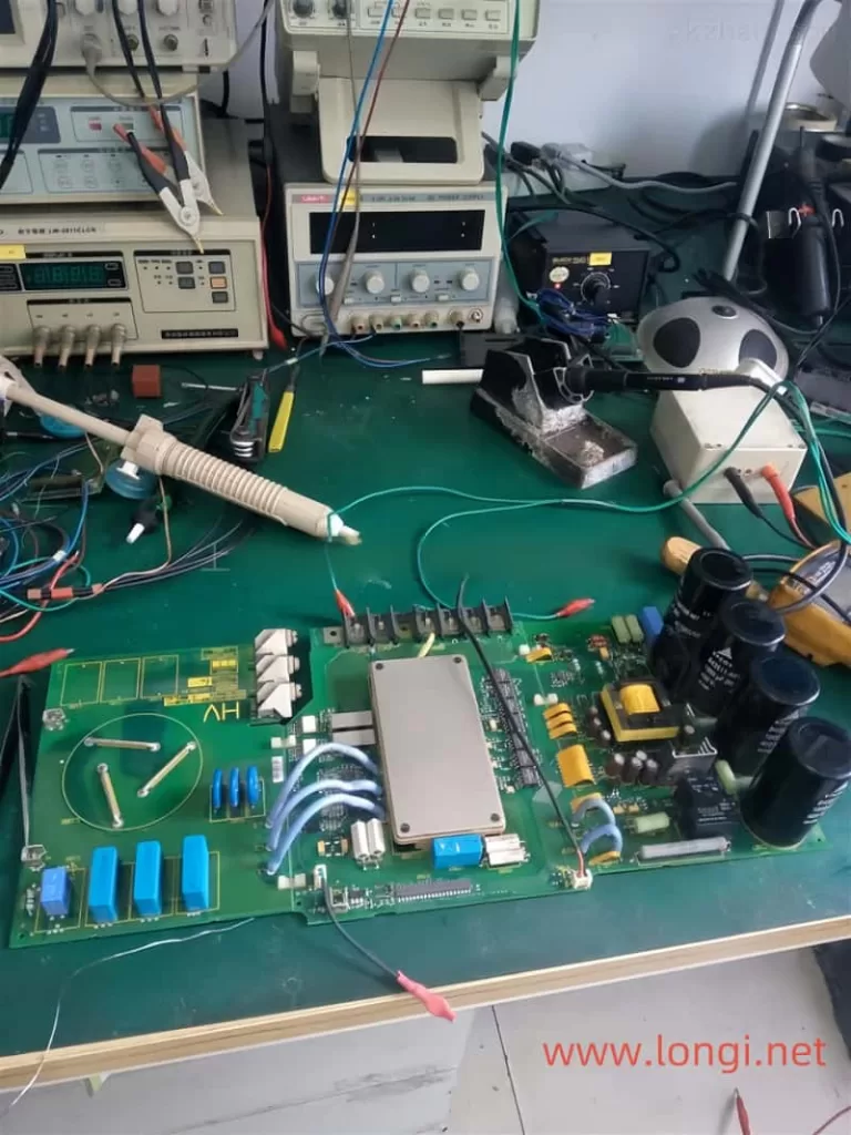
However, even after these repairs, the GF fault persisted. I then conducted a series of tests, including short-circuiting the module detection circuit’s transistors to relieve the fault protection function. During these tests, I observed an abnormal phenomenon: the series-connected light bulb lit up with high brightness after the start signal was activated, indicating a potential issue with the IGBT modules or driving circuit.
Discovering the Common Cause
After ruling out issues with the driving circuit and modules, I focused on the common factors that could affect all six protection circuits. I noticed that the leads of the capacitor bank, which were longer due to the repair setup, could be introducing inductance into the circuit. This inductance could generate induced electromotive force and current, interfering with the module fault detection circuit.
To test this hypothesis, I formally installed the machine, limiting the lead inductance of the capacitor bank within the allowable value. After the installation, the Yaskawa frequency converter operated normally without tripping the stubborn GF fault.
Conclusion
Repairing the GF fault in the Yaskawa 616G3 55kW frequency converter was a challenging but rewarding experience. By thoroughly understanding the protection circuit and methodically diagnosing each potential issue, I was able to repair the machine without replacing any major components. The key to solving the stubborn GF fault was identifying the common cause—inductance in the capacitor bank leads—and addressing it through proper installation.
This case study highlights the importance of logical reasoning and thorough investigation in repairing electronic equipment. It also demonstrates that, with patience and persistence, even stubborn faults can be resolved without resorting to costly board replacements.