
Introduction
Variable frequency constant pressure water supply systems are essential for maintaining stable water pressure in pipeline networks. This article delves into a specific system configuration that employs a Programmable Logic Controller (PLC) and a frequency converter to control two water pumps in a one-to-two drive setup. The system ensures continuous and stable water supply by automatically adjusting the pump operations based on pipeline pressure.
System Overview
The system primarily consists of a frequency converter, a PLC, and two water pumps. The control mechanism leverages the PID (Proportional-Integral-Derivative) and other related functions of the frequency converter, in conjunction with the PLC, to achieve automatic constant pressure water supply. Additionally, the system is equipped with an automatic/manual switching function, allowing manual control of the water pumps in case of a frequency converter fault.
Control Process
The control process of the system is as follows:
- Initial Start-Up: When the pipeline pressure drops below the set value, the frequency converter starts the first pump (#1 pump).
- Full Speed Operation: After running at full speed for a predetermined period, if the pipeline pressure still does not reach the set value, the PLC switches the #1 pump from frequency conversion to power frequency operation.
- Second Pump Activation: The frequency converter then starts the second pump (#2 pump), adjusting its speed based on the pipeline pressure to maintain constant pressure.
- Pump Switching: As water demand decreases and pipeline pressure increases, if the #2 pump’s speed drops to zero but the pipeline pressure remains high, the PLC stops the #1 pump operating at power frequency, allowing the #2 pump to maintain constant pressure.
- Cycle Continuation: When the pipeline pressure drops again, the #2 pump is switched to power frequency operation, and the frequency converter starts the #1 pump, adjusting its speed to maintain constant pressure. This cycle continues indefinitely.
Frequency Converter Settings
For the system to function correctly, the frequency converter must be configured with specific parameters:
- Start/Stop Control: Set to operate on external terminals.
- Parking Mode: Configured for free parking to avoid impact during frequency conversion/power frequency switching.
- PID Mode: Enabled, with the pressure setting value entered via the AUX terminal and the feedback signal entering via the VIN terminal.
- Control Terminals: Configured to output contact actions for frequency conversion faults, zero speed, and full speed.
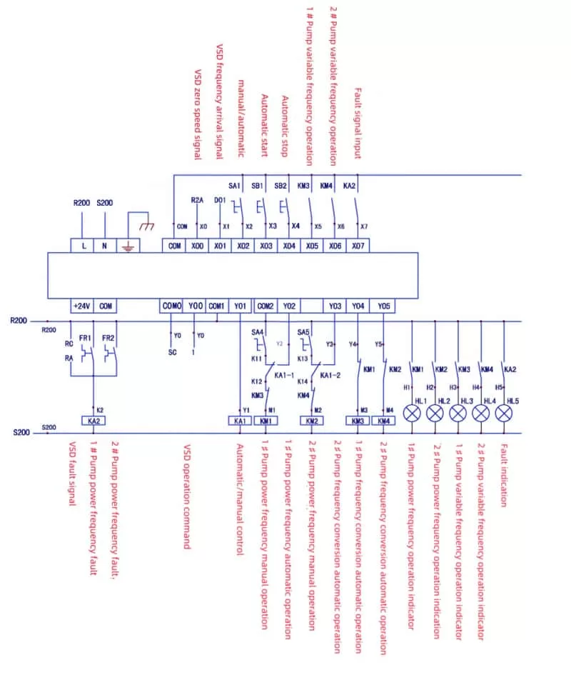
PLC Control Wiring and Program
The PLC control wiring diagram shows the integration of fault signals from the water pumps and frequency converter, summarized through relay KA2. The manual/automatic switching is controlled by relay KA1, while the frequency conversion/power frequency operation is interlocked via contactor contacts for enhanced safety.
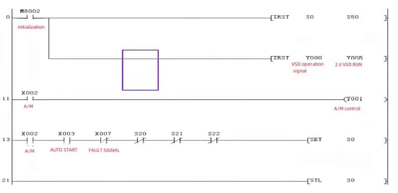
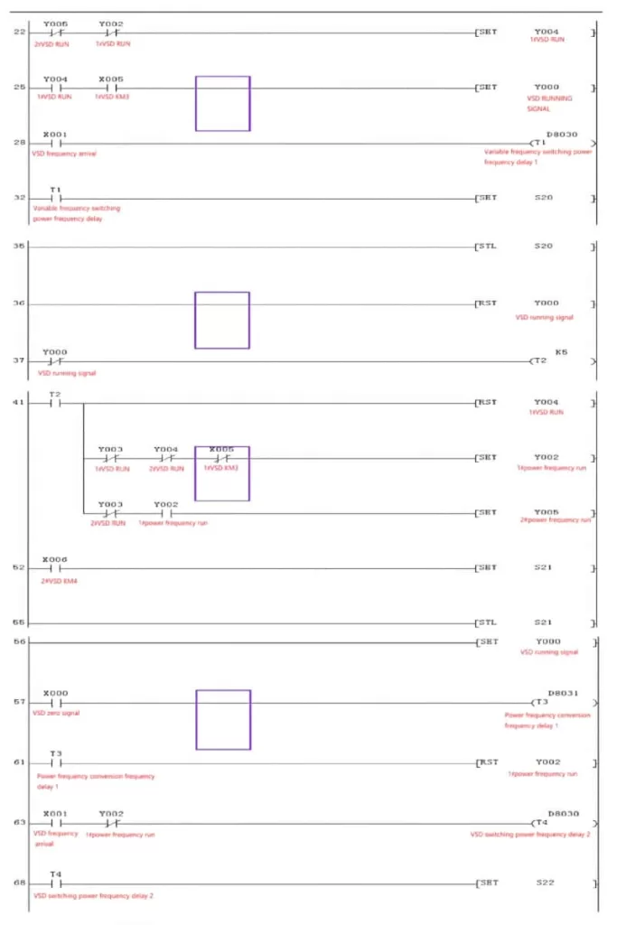
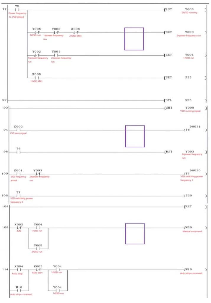
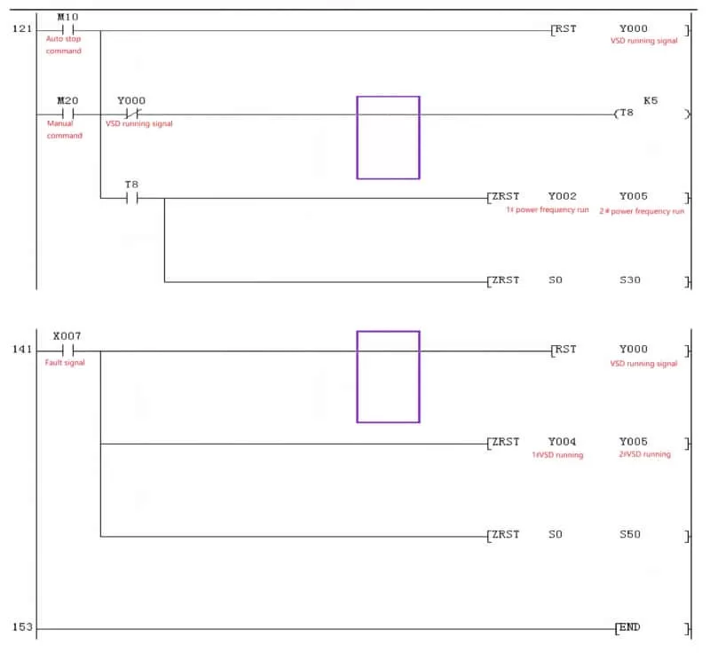
The PLC program is straightforward, consisting of four main steps (S20 to S23) that form a complete cycle. The switching time between frequency conversion and power frequency is adjustable via two potentiometers (D8030 and D8031) connected to the FX1S type PLC.
The program utilizes step instructions combined with set and reset commands. Step control begins with the STL instruction, and upon completion of all steps, a RET instruction returns the program to the starting step (S0). The SET command energizes the coil, while the RST command de-energizes it. The ZRST command is used for batch resetting multiple coils.
Technological Advancements and Alternative Solutions
As technology progresses, frequency converters are becoming more advanced, with some models capable of one-to-three or even one-to-six configurations. Automated instruments can also perform the PID function, allowing the frequency converter to work passively. In some setups, the frequency converter drives only one pump in a fixed manner, with the second pump directly switched to power frequency when needed. This approach, combined with timely pressure regulation by the frequency converter, results in more stable pipeline pressure.
Conclusion
The PLC-based variable frequency constant pressure water supply system with a one-to-two drive is a reliable and efficient solution for maintaining stable water pressure in pipeline networks. By leveraging the capabilities of PLCs and frequency converters, the system automatically adjusts pump operations to meet changing water demands. As technology continues to evolve, alternative solutions and configurations will emerge, offering even greater flexibility and efficiency in water supply management.