
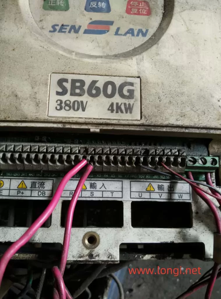
Maintenance and Fault Shielding Tips for Senlan Inverter SB40-S11-11KW Drive Circuit
When dealing with the repair of a Senlan SB40-S11-11KW frequency converter, it’s crucial to approach the process methodically to identify and resolve issues effectively. This article provides detailed insights and step-by-step guidance on troubleshooting and maintaining the drive circuit of this specific inverter model.
Initial Diagnosis
Upon inspecting a faulty Senlan SB40-S11-11KW frequency converter, you may encounter damage to the output terminals U and P+ of the module due to a breakdown. To begin the diagnostic process:
- Remove the Damaged Module:
Carefully remove the damaged module from the circuit. - Separate Circuit Board Testing:
Power on the circuit board independently to check for any abnormalities in the drive circuit. If an “OLE” fault appears, refer to the manual, which indicates an external alarm signal. - Short Circuit Control Terminal:
Short circuit the control terminal Thr to CM. If the power-on display returns to normal but an “FL” fault code appears when pressing the run button, this indicates a module failure.
Drive Circuit Analysis
The drive board is a complex circuit board with over twenty integrated blocks. To understand the fault:
- Examine Optocouplers:
Observe the six optocouplers on the back of the board, which are likely returning the “FL” fault to the CPU. These optocouplers’ outputs are typically parallel. - Short Circuit Optocoupler Inputs:
Short circuit all the input sides of the optocouplers and power on the board. If the “FL” fault does not appear, this indicates that the fault lies in the drive signals. - Check Drive Power Supplies:
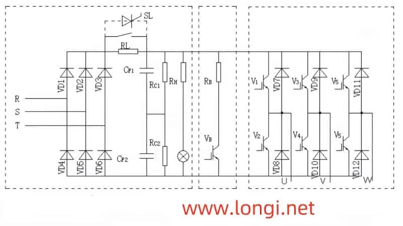
Measure the voltages on the trigger terminals of the IGBT modules. The drive power supplies for the U, V, and W IGBT tubes should be output by a switching power supply on the motherboard at 12V, then oscillated and inverted by an NE555 chip. A cylindrical sealed transformer extracts voltage from the secondary three windings and rectifies it to form three independent driving power supplies. Ensure all three power supplies are functioning.
Identifying the Issue
If there is no voltage on the trigger terminal of the module, it suggests a deeper issue:
- No Static Negative Pressure or Excitation Positive Voltage:
The absence of both static negative pressure and excitation positive voltage during operation indicates a problem in the drive circuit’s protection mechanism. - Protection Circuit Activation:
The large circuit board likely has a protection mechanism that detected an abnormally large “IGBT conduction voltage drop” due to the removed module. This activated the protection circuit, cutting off the signal on the module trigger terminal.
Bypassing Protection to Test
To test the drive circuit without the protection interference:
- Artificially Create IGBT Conduction:
Connect the upper three channels of the triggering terminal with the U, V, and W terminals directly. Connect the lower three channels to the N-point, artificially short-circuiting the lower three IGBT tubes. - Release Optocoupler Short Circuits:
Release the short circuits on the corresponding three optocouplers reporting the “FL” fault. - Power On and Test:
Power on the circuit and start the operation. If the “FL” fault is no longer reported and the trigger terminals of the lower three arms have normal pulse voltage output, this indicates the drive circuit is functioning correctly. - Repeat for Upper Arms:
Connect the upper three circuits of the trigger terminal to the U, V, and W terminals and to point P+. Artificially short-circuit the upper three IGBT tubes and test for normal pulse voltage output.
Conclusion and Repair
If both the upper and lower arms of the module have normal pulse voltage outputs, this confirms that the entire drive circuit and operation control are functioning correctly. You can then proceed with replacing the module.
Final Thoughts
- No Cut-Off Negative Pressure:
In the shutdown state, the triggering terminal voltage should be zero. This is normal and indicates proper operation of the cut-off mechanism. - Successful Repair:
After replacing the module, the frequency converter should be fully repaired and ready for use.
By following these logical and structured steps, you can effectively troubleshoot and repair the drive circuit of the Senlan SB40-S11-11KW frequency converter. Remember, a methodical approach and understanding of the circuit’s protection mechanisms are key to successful maintenance and repair.