I. Introduction to the Operation Panel Functions and Parameter Initialization Settings
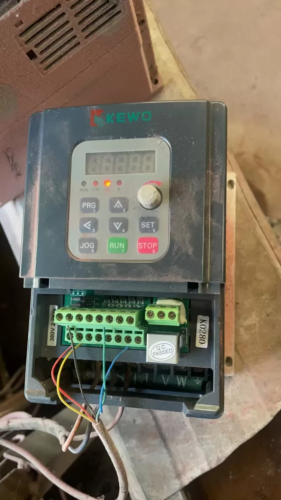
The operation panel of the KEWO Inverter AD350/AD150 series provides an intuitive user interface for easy parameter setting and monitoring. The operation panel typically includes a display screen, direction keys, a confirmation key, a run key, and a stop key.

Parameter Initialization Settings:
When initializing the inverter for the first time or restoring it to factory settings, the parameter initialization function can be used. The specific steps are as follows:
- Enter the functional parameter table (P group) and locate the P0.13 parameter (parameter initialization).
- Use the direction keys to select “01: Restore factory parameters, excluding motor parameters” or “12: Clear record information”, then press the confirmation key.
- The inverter will automatically perform the initialization settings and restart.
Password and Parameter Access Restrictions:
To prevent unauthorized parameter modifications, users can set passwords and parameter access restrictions to protect the inverter configuration.
- Enter the P7 group (keyboard and display group) and locate the P7.00 parameter (user password).
- Use the direction keys to set the desired password (0-65535), then press the confirmation key.
- Find the P7.03 parameter (parameter write protection) and select “1: Parameters not allowed to be modified” to enable parameter access restrictions.

II. Terminal Forward/Reverse Control and External Potentiometer Given Speed Regulation
Terminal Forward/Reverse Control:
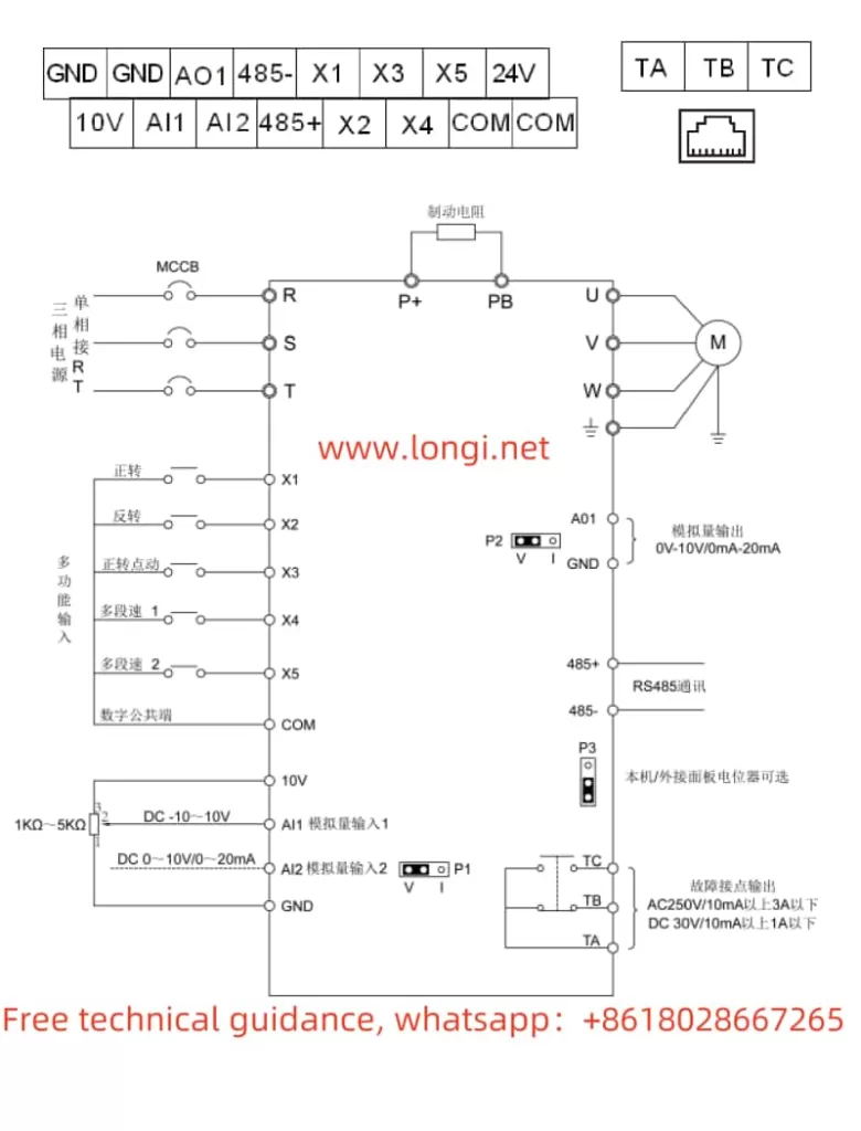
The KEWO Inverter supports forward/reverse control through external terminals. Typically, the X1 and X2 terminals are used as forward/reverse control terminals.
Wiring Steps:
- Connect the forward control signal line to the X1 terminal and the reverse control signal line to the X2 terminal.
- Ensure that the other end of the signal line is connected to the correct control source (such as a PLC output).
Parameter Settings:
- Enter the P5 group (input terminal group) and locate the P5.00 parameter (X1 terminal function selection).
- Use the direction keys to select “1: Forward operation (FWD)”, then press the confirmation key.
- Find the P5.01 parameter (X2 terminal function selection) and select “2: Reverse operation (REV)”, then press the confirmation key.
External Potentiometer Given Speed Regulation:
An external potentiometer can conveniently adjust the output frequency of the inverter to achieve speed regulation.
Wiring Steps:
- Connect the output terminal of the external potentiometer to the AI1 terminal (analog input terminal 1) and the other end to the GND terminal (ground terminal).
- Ensure that the power supply and signal lines of the potentiometer are connected correctly.
Parameter Settings:
- Enter the P0 group (basic parameter group) and locate the P0.03 parameter (main frequency selection).
- Use the direction keys to select “4: Panel potentiometer”, then press the confirmation key.
III. Fault Codes and Troubleshooting Methods
The KEWO Inverter AD350/AD150 series provides a wealth of fault codes to help users quickly locate problems and take corresponding measures.

Common Fault Codes and Troubleshooting Methods:
- E001 (Acceleration Overcurrent):
- Possible Causes: Too short acceleration time, output short circuit, improper motor parameter settings, etc.
- Solution: Increase the acceleration time, check the insulation of the motor and cable, perform motor parameter identification, etc.
- E002 (Deceleration Overcurrent):
- Possible Causes: Too short deceleration time, output short circuit, sudden load changes, etc.
- Solution: Increase the deceleration time, check the insulation of the motor and cable, check the load, etc.
- E007 (Control Power Supply Fault):
- Possible Causes: Abnormal input voltage, relay failure, etc.
- Solution: Adjust the input voltage to the normal range, check the relay status, etc.
- E015 (Motor Overload):
- Possible Causes: Excessive load, improper motor parameter settings, undersized inverter selection, etc.
- Solution: Check the load and mechanical condition, correctly set the motor parameters, replace the inverter with a higher power rating, etc.
- E024 (Communication Fault):
- Possible Causes: Upper computer fault, abnormal communication line, incorrect communication parameter settings, etc.
- Solution: Check the upper computer and connection line, check the communication line, correctly set the communication parameters, etc.
The KEWO Inverter AD350/AD150 series user manual provides detailed operation guides and fault diagnosis methods to help users quickly get started and resolve issues encountered during use. Through reasonable parameter settings and wiring, users can fully utilize the performance of the inverter to achieve efficient and stable motor control.
