Table of Contents
- Panel Start, Stop, and Frequency Speed Adjustment
- Panel Start and Stop Operation
- Panel Frequency Speed Adjustment Settings
- Manual Adjustment of Voltage/Frequency Ratio Parameters
- Inverter Initialization Procedure
- Password and Parameter Access Restriction Settings
- Terminal Forward/Reverse Control and External Potentiometer Speed Adjustment
- Terminal Forward/Reverse Control Settings
- External Potentiometer Frequency Speed Adjustment Settings
- Explanation of Required Terminal Connections
- Fault Codes and Troubleshooting
- List of Common Fault Codes
- Fault Meanings Analysis
- Troubleshooting Methods

1. Panel Start, Stop, and Frequency Speed Adjustment
Panel Start and Stop Operation
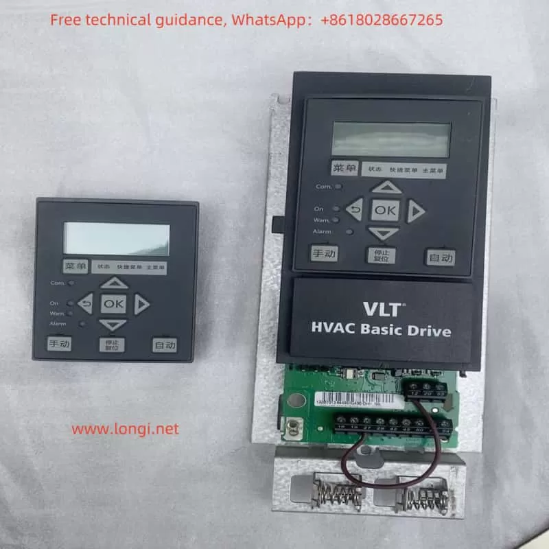
The Danfoss FC 101 series inverter can be started and stopped via the Local Control Panel (LCP). The specific operations are as follows:
- Start: Press the “[Hand On]” key on the LCP to start the motor.
- Stop: Press the “[Off/Reset]” key on the LCP to stop the motor. This key can also be used to reset alarms in alarm mode.
Panel Frequency Speed Adjustment Settings
To achieve panel-based frequency speed adjustment, the following parameters need to be set:
- 3-02 Minimum Reference Value: Sets the minimum allowable frequency reference value.
- 3-03 Maximum Reference Value: Sets the maximum allowable frequency reference value.
- 3-10 Preset Reference Value: Used to set one or more preset frequency reference values, selected via keys on the LCP.

Manual Adjustment of Voltage/Frequency Ratio Parameters
To manually adjust the voltage/frequency (V/F) ratio curve, the following parameters need to be set:
- 1-01 Motor Control Principle: Select [0] U/f control.
- 1-55 U/f Characteristic – U: Set corresponding voltage values for different frequency points.
- 1-56 U/f Characteristic – F: Define the frequency points in the V/F characteristic curve.
Inverter Initialization Procedure
Initializing the inverter restores its parameters to default settings. There are two initialization methods:
- Recommended Initialization:
- Select parameter 14-22 Operation Mode.
- Press the [OK] key, select [2] Initialize, and then press the [OK] key again.
- Disconnect the inverter power supply and wait for the display to turn off.
- Reconnect the main power supply.
- Two-Finger Initialization:
- Disconnect the inverter power supply.
- Simultaneously press and hold the [OK] and [Menu] keys.
- Hold the keys for 10 seconds while powering on the inverter.
Password and Parameter Access Restriction Settings
- 0-60 Main Menu Password: Defines the password for accessing the main menu.
- 0-61 Extended Menu No Password: Choose between full access, read-only, or no access.
2. Terminal Forward/Reverse Control and External Potentiometer Speed Adjustment
Terminal Forward/Reverse Control Settings
To achieve terminal-based forward/reverse control, the following parameters need to be set:
- 4-10 Motor Speed Direction: Select [2] Bidirectional to allow both clockwise and counterclockwise rotation.
- 5-10 Terminal 18 Digital Input: Set to [10] Reverse to control motor reversal.

External Potentiometer Frequency Speed Adjustment Settings
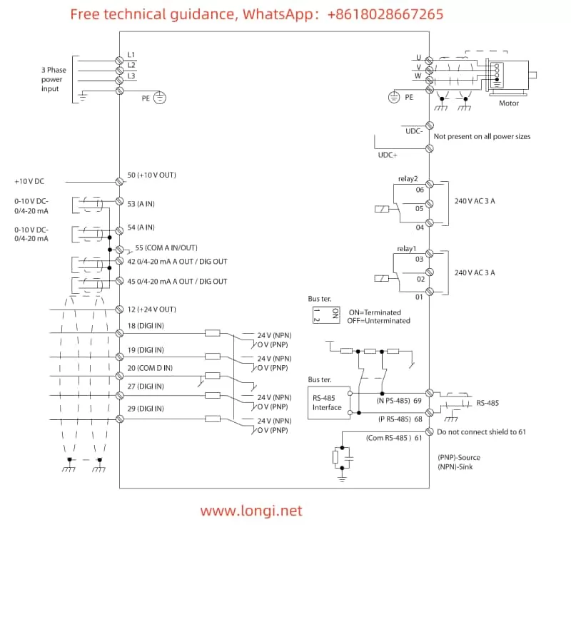
To achieve external potentiometer-based frequency speed adjustment, the following parameters need to be set, and terminal 53 (analog input) needs to be connected:
- 3-15 Reference Source 1: Select [1] Analog Input 53.
- 6-00 Disconnect Timeout Time: Set the timeout time for analog input disconnection.
- 6-01 Disconnect Timeout Function: Select the function when disconnected, such as lock output or stop.
Explanation of Required Terminal Connections
- Terminal 18: Connect the digital input signal for reverse control.
- Terminal 53: Connect the external potentiometer for frequency speed adjustment.
- Terminal 27: Typically used for start/stop control, specific function needs to be set in parameters.
3. Fault Codes and Troubleshooting
List of Common Fault Codes
- Alarm 2: Disconnect Fault
- Alarm 3: No Motor Connected
- Alarm 4: Main Supply Phase Loss
- Alarm 13: Overcurrent
- Alarm 14: Earth Fault
- Alarm 24: Fan Fault
- Alarm 30: Motor Phase U Loss
- Alarm 95: Broken Belt
Fault Meanings Analysis
- Disconnect Fault: Analog input signal is below the set value.
- No Motor Connected: No motor is connected to the inverter output terminals.
- Main Supply Phase Loss: Main power supply has missing phases or unstable voltage.
- Overcurrent: Motor current exceeds the inverter peak current limit.
- Earth Fault: Output phase is discharged to earth through motor cables or the motor itself.
- Fan Fault: Fan is not running or not installed.
- Motor Phase Loss: One phase is missing between the motor and the inverter.
- Broken Belt: Torque is below the set value, indicating a possible broken belt.
Troubleshooting Methods
- Disconnect Fault: Check analog input terminal connections and signal source.
- No Motor Connected: Check motor connections to the inverter.
- Main Supply Phase Loss: Check main power supply and voltage stability.
- Overcurrent: Check motor load and parameter settings to ensure motor compatibility.
- Earth Fault: Check motor cable and grounding connections.
- Fan Fault: Check fan resistance and operation.
- Motor Phase Loss: Check motor connections and cables.
- Broken Belt: Check the drive system and belt condition.
By following the above settings and troubleshooting methods, users can effectively operate and maintain the Danfoss FC 101 series inverter, ensuring its stable operation and meeting application requirements.
