Introduction
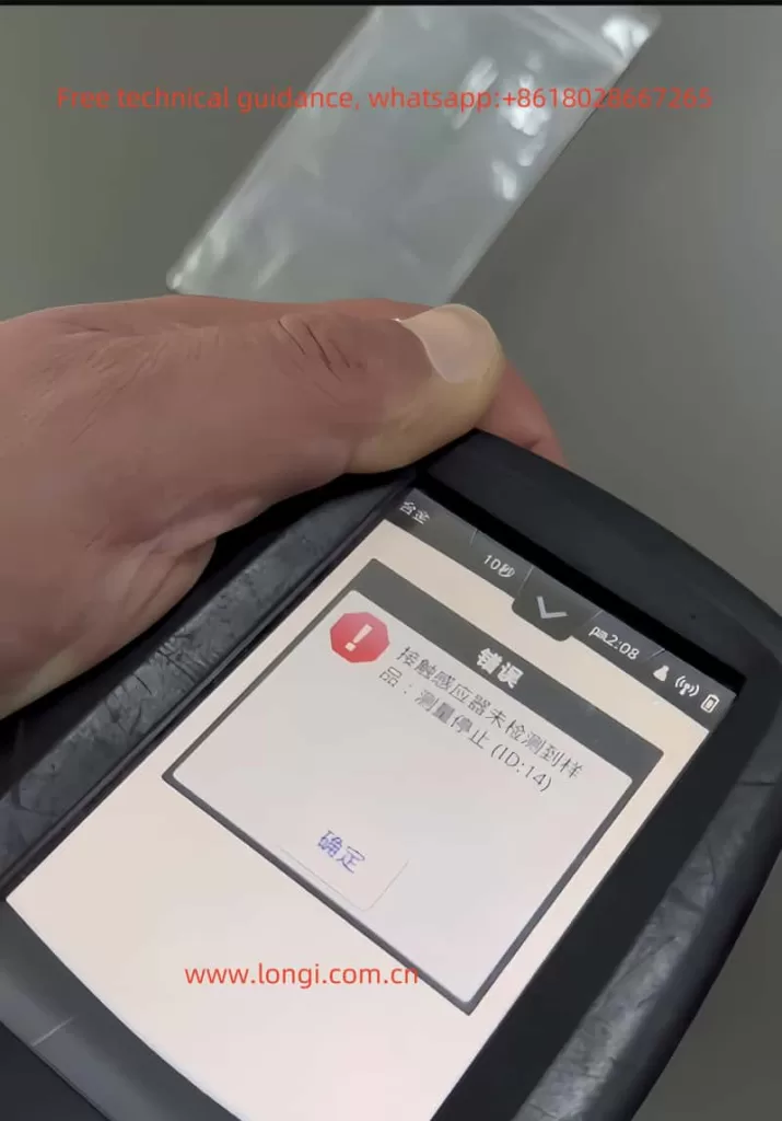
The X-MET8000 is a portable spectrometer developed by Hitachi, widely used in industrial fields such as metal composition analysis and material testing. Its core technology relies on the collaboration between the X-ray emission and reception system and the sample sensor to achieve precise analysis. However, users may encounter the ID-14 error, which indicates “Sample proximity sensor not detected, measurement stopped.” This issue not only affects work efficiency but may also cause damage to the device or inaccurate measurements. This article delves into the causes of the ID-14 error and provides detailed solutions based on practical repair experience.

1. The Meaning of ID-14 Error
The key to the ID-14 error lies in the message “Sample proximity sensor not detected.” Essentially, the detection system of the spectrometer cannot confirm whether the sample is properly placed. This is usually caused by the following three factors:
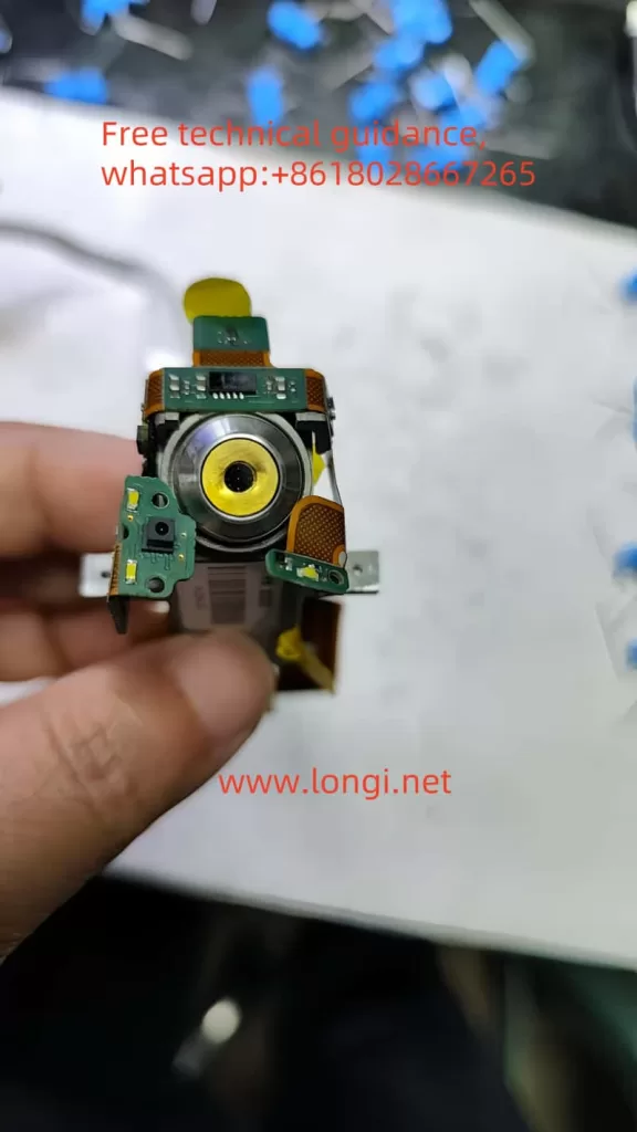
- Failure of the sample sensing system: The spectrometer uses an infrared sensor to detect whether the sample is in contact with the measurement window. A failure in this system may lead to detection errors.
- Issues with sample placement: If the sample does not completely cover the measurement window, has an uneven surface, or is unsuitable for measurement, this error will occur.
- Internal hardware or circuit issues: This includes failures in the infrared sensor, connecting circuits, or signal processing modules.

2. Causes of the Error
Based on repair experience and the working principle of the device, the specific causes of the ID-14 error include:
1. Improper Sample Placement
- The sample does not fully cover the measurement window.
- The sample surface contains oil, oxide layers, or other obstructions, blocking the infrared signal.
- The sample has an irregular shape (e.g., curved or uneven), making it difficult to contact the sensor tightly.
2. Infrared Sensor Issues
The infrared sensor is a key component related to the ID-14 error, with potential issues including:
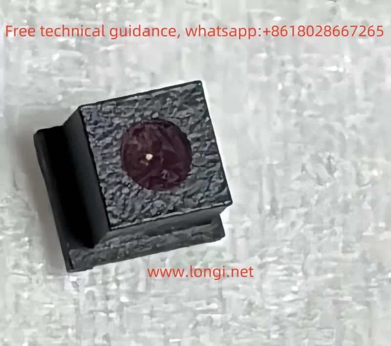
- Damage to the infrared emitter or receiver: The emitter cannot emit infrared signals, or the receiver cannot capture the reflected signals.
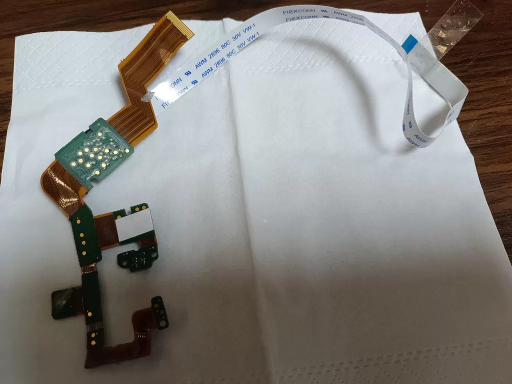
- Cold solder joints: Prolonged use may lead to loose or broken solder joints between the sensing module and the FPC (flexible printed circuit).
- Contamination or aging: Pollution on the sensor surface or aging components may weaken or disable the signal.
3. Circuit Connection Failures
- FPC damage: The flexible circuit board connecting the sensing module to the mainboard may break due to bending, pulling, or prolonged use.
- Connector issues: The FPC connector to the mainboard may not be tightly connected, or the contacts may be oxidized.
4. Control Circuit Issues
- Infrared signal processing chip failure, preventing proper signal transmission.
- Other related circuits on the mainboard (e.g., power supply modules) may malfunction, affecting the infrared module’s operation.

3. Solutions
Based on the above analysis, repair steps can be divided into the following aspects:
1. Checking the Sample
Before disassembling the device or performing more complex repairs, inspect the sample:
- Clean the sample surface: Use isopropyl alcohol to clean the sample surface to remove oil, oxide layers, or dust.
- Reposition the sample: Ensure the sample fully covers the measurement window and is in close contact with the sensor.
- Replace the sample: If the sample surface is too rough or irregular, choose another sample for testing to rule out sample-related factors.

2. Repairing the Sensor Module
If the sample is confirmed to be fine, focus on the sensor module:
- Clean the infrared sensor: Use a lint-free cloth and isopropyl alcohol to clean the emitter and receiver surfaces, removing dust or stains.
- Test the infrared emitter and receiver:
- Use a multimeter to measure whether the emitter and receiver output signals.
- Use an infrared camera or night vision device to check if the infrared emitter is emitting light (usually at 850nm or 950nm wavelengths).
- Replace damaged sensor modules: If the sensor is confirmed to be faulty, replace it with a module of the same model.
3. Repairing Circuit Connections
- Inspect the FPC:
- Use a multimeter to measure whether all lines on the FPC are continuous.
- If a break is found, repair it with fine wires or replace the entire FPC.
- Repair solder joints:
- Use a hot air rework station or a fine-tip soldering iron to re-solder the sensor module. Keep the soldering temperature between 280–320°C.
- If the solder joints are aged or loose, remove the old solder and reapply fresh solder.
- Check the connectors: Clean the connector contacts between the FPC and the mainboard. Replace the connector if necessary.
4. Checking the Mainboard and Control Circuits
- Use an oscilloscope to check whether the signal processing chip on the mainboard is functioning correctly.
- If the mainboard is faulty, contact the manufacturer for replacement or repair.

4. Repair Precautions
- Safety First:
- The X-MET8000 involves X-ray technology. Ensure the device is completely powered off before operation, and avoid contact with high-voltage parts.
- Do not operate the X-ray system without proper safety measures.
- Tool Preparation:
- Prepare tools such as a hot air rework station, multimeter, isopropyl alcohol, lint-free cloth, tweezers, etc.
- Use a microscope if possible to assist with observation and soldering.
- Avoid Misoperation:
- During repairs, avoid damaging surrounding components or circuits.
- If you lack repair experience, consider handing the device over to professional technicians.
5. Conclusion
The ID-14 error is a common issue in Hitachi’s X-MET8000 spectrometer, usually caused by failures in the sample sensor or related circuits. Through systematic troubleshooting and repair methods, this issue can be effectively resolved, restoring the device to normal operation. This article combines practical repair cases to analyze the issue from four aspects: sample inspection, sensor module, circuit connection, and mainboard circuits, providing a clear troubleshooting framework for repair technicians.
In practice, repair personnel should flexibly adjust steps according to specific circumstances and ensure safety precautions are in place. If the issue persists, it is recommended to contact the manufacturer’s technical support for further assistance.

We have the following Hitachi X-MET 8000Model XMDS 2770 Serial Number 802908 MFG July 2018. We have not used this tool very much but now want to use it. Our previous user has left the company but we are having an error message ID-14 when we try and test it on the sample. Can you advise what the likely issue is. We are located in Southern Iraq near Basra. We are an Oilfield Service Company. If the tool needs servicing can you advise the nearest of your service centres.
thankyou
ok