
When dealing with variable speed drives (VSDs), encountering unusual faults can be both perplexing and time-consuming. This article will delve into two unique faults encountered in an Anbang Xin AMB-G9/P9 22kW frequency converter and provide step-by-step solutions to resolve them.
Fault A: Mysterious “Fault Characters”
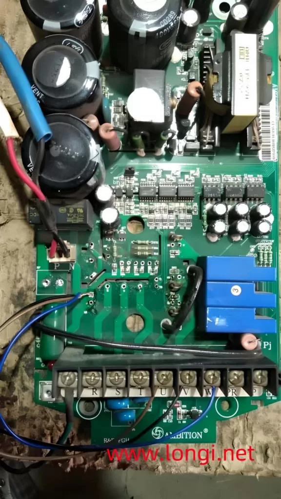
A user sent in a domestically produced frequency converter for repair, specifically an Anbang Xin AMB-G9/P9 22kW model. Upon initial inspection, the damaged module was removed, and the drive circuit was tested for normalcy. Upon powering on, the operation panel displayed an OC fault code. Once the short-circuit fault signal was addressed, the OC signal stabilized. However, when attempting to run the converter by pressing the RUN button, the charging relay momentarily disconnected, causing the panel indicator light to go out and the display screen to flash a series of unrecognizable “fault characters” not listed in the fault code table.
Diagnosis and Solution:
- Identify the Anomaly:
- The output terminals of the three-phase output current detection signal were all at 0V, which is normal.
- Occasionally, upon cycling the power, it was discovered that the “fault characters” were actually startup characters.
- Root Cause Analysis:
- The malfunction indicated a possible short-circuit load on the switching power supply’s load side, particularly in the driving circuit.
- When the startup signal was activated, the power supply voltage dropped significantly, causing the switching power supply to stop oscillating.
- This voltage drop also released the charging relay due to insufficient suction voltage, prompting the CPU to believe it was being re-powered on and displaying startup characters.
- Circuit Inspection:
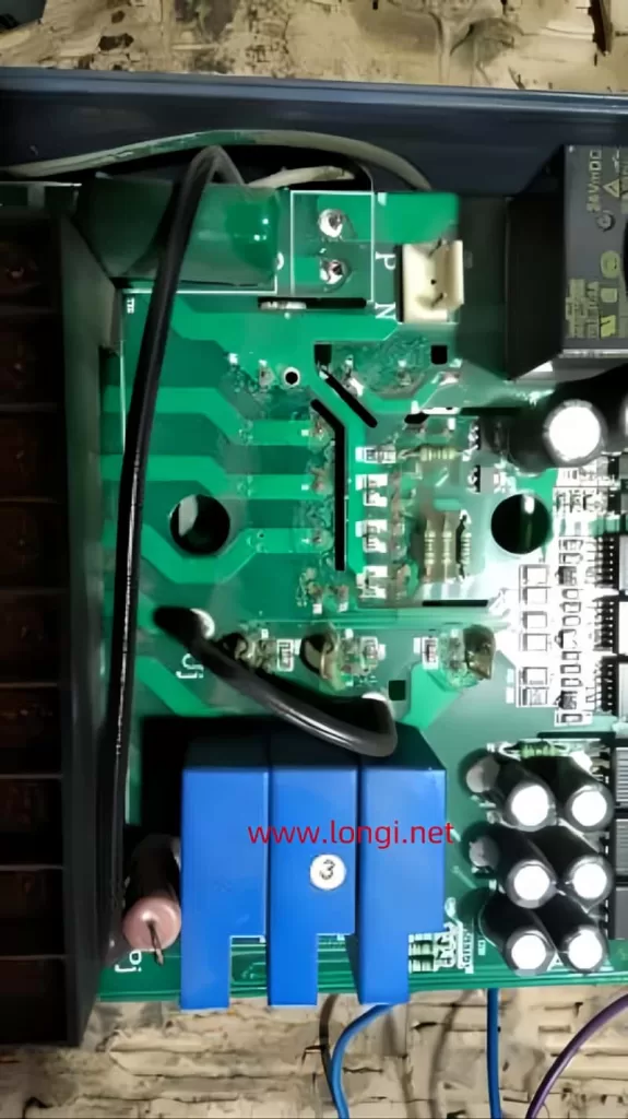
- Examination of the driving circuit revealed that two power amplification tubes, connected in a push-pull configuration behind the driving IC, had sustained damage.
- One transistor in both the upper and lower arm driving power amplifier circuits of the U-phase was damaged.
- This damage caused an instantaneous short circuit to the driving power supply when pulse signals arrived, resulting in a momentary shutdown.
- Resolution:
- Conduct a thorough inspection of the driver board before powering on after dismantling the module.
- Replace the damaged transistors in the driving circuit to ensure proper pulse amplification and module driving.
Fault B: Unlisted Fault Characters Related to the Brake Circuit
After replacing the module, the converter was tested with a 24V DC power supply without connecting the 530V DC voltage of the DC circuit. Upon startup, the Br Tr FeiLuRe character appeared but could be reset with the reset button. However, disconnecting the 24V power supply resulted in the fault persisting and becoming unresettable.
Diagnosis and Solution:
- Initial Checks:
- The fault code was checked, and the manufacturer indicated it was a brake circuit fault, which seemed unusual given that the external brake resistor circuit was not connected.
- Internal brake components were measured and found to have no short circuits.
- Voltage Analysis:
- Upon disconnecting the 24V power supply, a residual voltage of about 6V was found at the inverter power supply terminal.
- This voltage entered the fault detection circuit, potentially triggering the Br Tr FeiLuRe fault signal.
- Circuit Examination:
- The negative pressure and pulse positive voltage of the six drive circuits were normal.
- With the guarantee of cut-off negative pressure, connecting the 530V DC voltage to the DC circuit should not damage the module.
- Testing and Resolution:
- For safety, the original 75A quick release fuse was replaced with a 2A one.
- Everything operated normally after this change, indicating that a faulty fuse or short-circuited brake control IGBT inside the module could generate the Br Tr FeiLuRe alarm.
- The fault detection circuit likely reported an abnormal low voltage in the DC circuit to the CPU as a brake circuit fault.
- Final Considerations:
- Defining the fault as a brake circuit issue may be misleading.
- The occurrence of this fault prevented low-voltage power supply testing of the inverter circuits, increasing maintenance costs and complexity.
Conclusion
Encountering unusual faults in VSDs requires a systematic approach to diagnosis and resolution. By carefully examining circuit components, analyzing voltage anomalies, and conducting thorough testing, these complex issues can be resolved effectively. This case study highlights the importance of detailed inspection and the potential pitfalls of misdiagnosed faults, ultimately leading to successful repairs and improved understanding of VSD operation.