
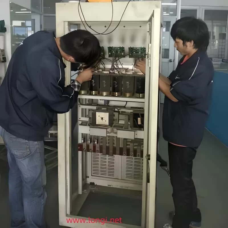
When dealing with complex electronic devices like frequency converters, troubleshooting can often be a challenging task. This article presents a detailed case study of a 5.5kW Convo frequency converter that was sent for repair due to issues with its operation. Despite having output, the converter was unable to operate with a load, the motor couldn’t rotate, and the operating frequency couldn’t be adjusted.
Initial Examination and Tests
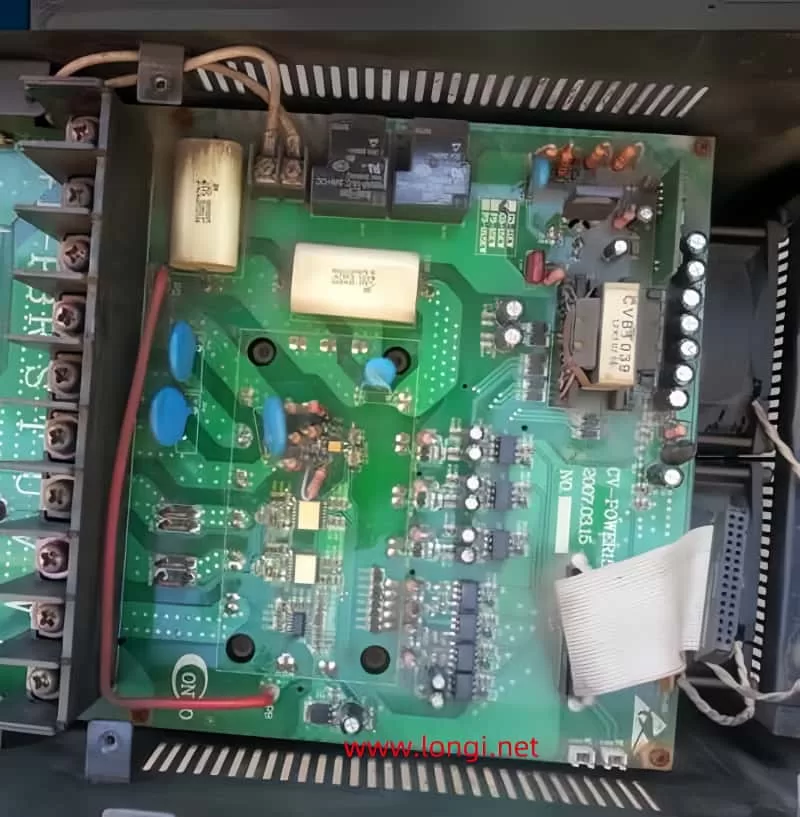
Upon receiving the unit, the main circuit, rectifier, and inverter circuits were thoroughly checked and found to be normal. With no load connected, the three-phase output voltage was also measured and deemed normal. However, when a 1.1kW no-load motor was connected and the frequency converter was started, the frequency couldn’t rise above one or two hertz. The motor would pause and produce a creaking sound, with no overload or OC fault reported.
Investigating the Drive Circuit
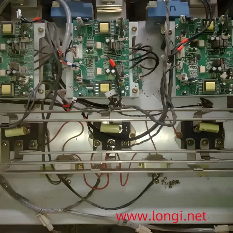
Suspecting an issue with the drive circuit, the 550V DC power supply of the inverter module was disconnected, and a 24V DC low-voltage power supply was used to check the drive circuit. All capacitors and components in the drive circuit and drive power supply circuit were normal. The positive and negative pulse currents output by the three-arm drive circuit on the inverter output had reached a sufficient amplitude, indicating that there should be no issue driving the IGBT module.
However, when measuring the pulse currents, a module fault was reported. Upon analysis, it was discovered that the multimeter’s DC current range had been directly short-circuited to measure the triggering terminal, lowering the positive excitation voltage output by the drive circuit. This voltage drop prevented the IGBT tube from being triggered normally and reliably, leading to the OC module fault. When the measurement method was adjusted by connecting the probe in series with a resistance of over ten ohms, the OC fault was no longer reported.
Further Investigation
With the drive circuit functioning normally, the signal output circuit of the current transformer was also checked and found to be normal. During operation, no fault signal was reported, leaving the technician puzzled.
Considering the possibility that the CPU might be detecting abnormal current during startup and taking measures to slow down, the technician explored various potential causes:
- Abnormal Current Detection: Could the CPU be detecting a sharp increase in abnormal current values and performing immediate frequency reduction processing?
- Driving Circuit Issues: Was the current limiting action due to abnormal driving or poor module performance?
Attempts to short-circuit the shunt resistors of the U, V, and W output circuits to make the CPU exit the frequency reduction and current limiting action were ineffective. Restoring the parameters to their factory values also had no impact.
Observing the Frequency Converter’s Behavior
Upon starting the frequency converter and observing its behavior, it was noticed that after the speed rose to 3Hz, it would drop to 0Hz and repeat this process. The motor would stop running. When the acceleration time was significantly increased, the speed steadily increased to 3Hz and then decreased to 0Hz, indicating that there were no abnormalities in the drive and other circuits. This operating phenomenon seemed to be based on a signal emitted by the CPU, possibly as a current limiting action based on the current signal.
Focusing on Voltage
With the drive and current detection circuits functioning normally, the technician shifted their focus to voltage. The anomalies caused by voltage could be divided into two aspects:
- Abnormal DC Voltage Detection Circuit: This could be due to the drift of the reference voltage, variation of sampling resistance, or other issues. This signal might cause the CPU to mistakenly assume that the voltage is too low and take measures to reduce the output frequency.
- Abnormality of the Main DC Circuit: This could result in low voltage due to issues like loss of capacity of the energy storage capacitor or failure to close the charging short-circuit contactor.
Discovery of the Issue
Upon reinstalling and powering on the machine for a motor test, it was noticed that there was no sound of the charging contactor closing. Checking the contactor coil revealed that it was supposed to receive AC 380V from the R and S power supply incoming terminals. However, loose coil lead terminals had caused poor contact, preventing the contactor from engaging. The large current during startup created a significant voltage drop on the charging resistor, which was detected by the voltage detection circuit, prompting the CPU to issue a frequency reduction command.
Conclusion
The reason for the detour in troubleshooting was that the machine only performed frequency reduction treatment when the voltage dropped and did not report an undervoltage fault. In this case, other models might have reported an undervoltage fault. Due to the no-load condition, the voltage quickly rose during frequency reduction processing, allowing the frequency to continue to rise. This repeated process caused the frequency converter to increase speed, decrease to zero speed, pause, and then repeat the cycle without shutting down or reporting any fault signals.
This case study highlights the importance of thorough investigation and detailed observation in troubleshooting complex electronic devices. Relying solely on surface phenomena and past experience can lead to misdiagnosis and unnecessary repairs. By delving deeper into the issue and considering all potential causes, the technician was able to identify and fix the problem, ensuring the frequency converter’s proper operation.