I. Introduction to Operation Panel Functions
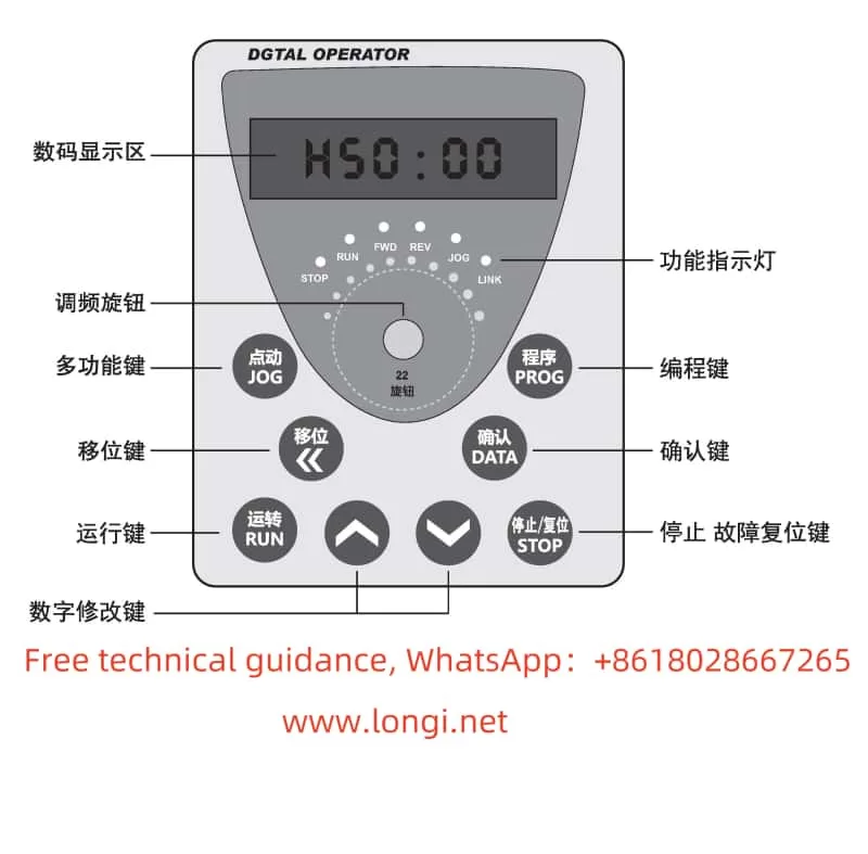
The Instar-Tech AE200H series frequency converter features a concise and straightforward operation panel design, facilitating intuitive operation and monitoring. The main function keys and indicator lights on the operation panel include:
- RUN Key: Press this key to start the frequency converter. In programming mode, this key can be used as a shift key.
- JOG Key: Press this key to enter jogging mode and switch between forward and reverse rotation.
- STOP Key: Press this key to stop the frequency converter. After a fault alarm, pressing this key can reset the system.
- PROG Key: Press this key to enter the function setting mode. After modification, press it again to exit the setting mode.
- DATA Key: In programming mode, press this key to confirm the function code and parameter content. After modification, press it again to save the data.
- UP Key and DOWN Key: In programming mode, use these keys to adjust the numerical values of function codes and parameter data.
- Shift Key (<< / REV): In programming mode, use this key to shift during parameter data modification.
Additionally, the operation panel has multiple indicator lights to display the operating status of the frequency converter, such as the RUN, STOP, FWD, and REV indicators.

II. Password Setting and Parameter Access Restrictions
To protect the frequency converter’s settings from unauthorized modification, the AE200H series provides a password setting function. Users can set a password to restrict access and modification of frequency converter parameters. The specific steps are as follows:
- Set Password: Enter programming mode, locate the user password parameter (e.g., P.089), and set a non-zero value as the password.
- Enter Password: When modifying parameters, the system will prompt for a password. Only by entering the correct password can you access the parameter modification interface.
- Eliminate Password: To eliminate the password, simply reset the user password parameter value to 0.
Furthermore, the AE200H series frequency converter offers parameter access restriction functions. Users can set different access levels to restrict different users’ access to frequency converter parameters.
III. Parameter Initialization
If users need to restore the frequency converter to its factory settings, they can perform a parameter initialization operation. The specific steps are as follows:
- Enter programming mode.
- Locate the factory reset parameter (e.g., P.XXX, refer to the user manual for specific codes) and set its value to 1.
- Press the DATA key to save the setting and restart the frequency converter.
After restarting, the frequency converter will return to its factory settings, and all user-set parameters will be cleared.
IV. Terminal Forward/Reverse Control and External Potentiometer Speed Regulation
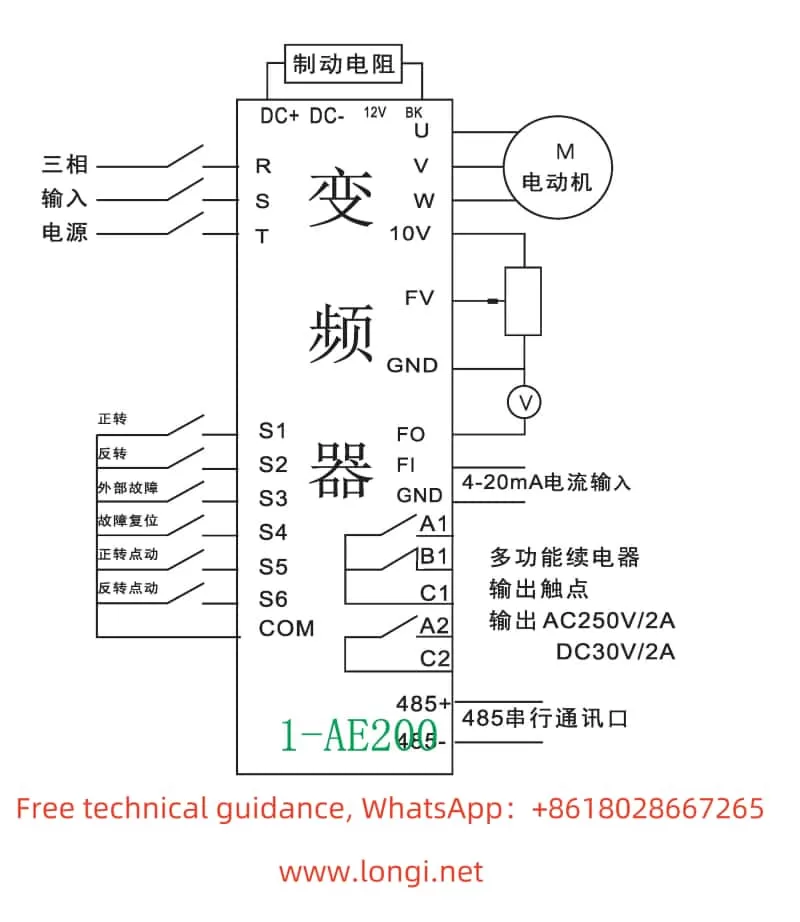
The AE200H series frequency converter supports motor forward/reverse control through external terminals and speed regulation through an external potentiometer. The specific settings and wiring methods are as follows:
- Terminal Forward/Reverse Control
- Parameter Setting: No special setting is required; ensure correct wiring.
- Wiring Method: Connect the forward control terminal (e.g., S1) and reverse control terminal (e.g., S2) to the corresponding contacts in the control circuit. By controlling the on/off status of these contacts, you can achieve motor forward/reverse rotation and stopping.
- External Potentiometer Speed Regulation
- Parameter Setting: Locate the speed control mode selection parameter (e.g., P.XXX) and set its value to external given.
- Wiring Method: Connect the output terminal of the external potentiometer to the speed regulation input terminal of the frequency converter (e.g., AI1 or AI2). By adjusting the resistance value of the potentiometer, you can change the output frequency of the frequency converter, thereby achieving motor speed regulation.
V. Fault Codes and Solutions
The AE200H series frequency converter features comprehensive fault diagnosis capabilities. When a fault occurs, the corresponding fault code will be displayed on the screen. Here are some common fault codes, their meanings, and solutions:
- OC1/OC2/OC3: Overcurrent during acceleration/deceleration/constant speed.
- Meaning: The output current of the frequency converter exceeds the rated value.
- Solution: Check if the motor load is excessive, check the power line connection for good contact, and check if the frequency converter parameter settings are reasonable (e.g., acceleration/deceleration time, overload protection).
- OU1/OU2/OU3: Overvoltage during acceleration/deceleration/constant speed.
- Meaning: The input voltage of the frequency converter is too high or the braking resistor is damaged.
- Solution: Check if the power supply voltage is stable and inspect the braking resistor for damage or poor connection.
- UV: Undervoltage on the bus.
- Meaning: The input voltage of the frequency converter is lower than the rated voltage.
- Solution: Check if the power supply voltage is normal and inspect the power line connection for good contact.
- OL1: Motor overload.
- Meaning: The motor load is excessive or the motor parameter settings are incorrect.
- Solution: Check if the motor load is excessive and verify the motor parameter settings (e.g., rated current, power).
- OH2: Frequency converter overheat.
- Meaning: The internal temperature of the frequency converter is too high.
- Solution: Check if the frequency converter installation environment is well-ventilated and inspect the cooling fan for normal operation.

VI. Conclusion
This article provides a detailed operation guide for the Instar-Tech AE200H series frequency converter, covering the introduction to operation panel functions, password setting and parameter access restrictions, parameter initialization, terminal forward/reverse control, external potentiometer speed regulation, fault codes and solutions, and other related content. We hope this guide will help users better understand and utilize this series of frequency converters to ensure their efficient and stable operation.
