I. Introduction to Operation Panel Functions and Parameter Settings
Introduction to Operation Panel Functions
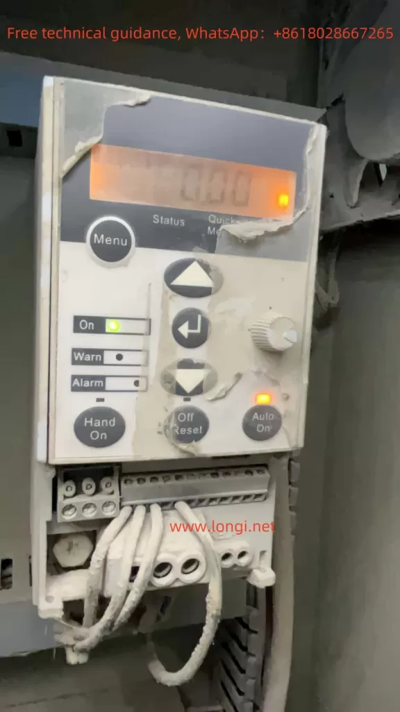
The operation panel (LCP operator) of the HOLIP HLP-SV series frequency converter provides an intuitive interface for users to set parameters and monitor operations. The operation panel mainly includes a display screen, function keys, navigation keys, potentiometers, and indicators. The display screen shows current parameters, converter status, and other data. The function keys are used to select menus and execute operations. The navigation keys allow for setting, switching, and changing operations within parameter groups, parameters, and parameter internals. The potentiometer is used to adjust motor speed in manual mode. The indicators show the operating status of the converter, such as power access, warnings, and alarms.

Initializing Parameters
To initialize the converter parameters, users can set parameter 14-22 to 2 to restore the converter to factory defaults. This operation will reset all parameters except parameters 15-03 (operating hours counter), 15-04 (overheat count), and 15-05 (overvoltage count) to their factory default values. Before performing this operation, ensure that important parameter settings have been backed up.
Setting and Removing Passwords
To prevent unauthorized parameter modifications, users can set a password. Parameter 0-60 can be used to set a password for the main menu, with a range of 0-999. After setting the password, only by entering the correct password can protected parameters be modified. To remove the password, simply set parameter 0-60 to 0.

Setting Parameter Access Restrictions
The HOLIP frequency converter provides parameter access restriction functions. Users can control the activation and editing permissions of different menus by setting parameters 0-10, 0-11, and 0-12. For example, setting parameter 0-10 to 1 or 2 can activate Menu 1 or Menu 2, respectively. Setting parameter 0-11 to 1 or 2 allows editing of Menu 1 or Menu 2, respectively. Setting parameter 0-12 to 20 enables parameter association between Menu 1 and Menu 2, ensuring that parameters that cannot be changed during operation can be synchronized between the two menus.
II. Terminal Forward/Reverse Control and External Potentiometer Speed Regulation
Terminal Forward/Reverse Control
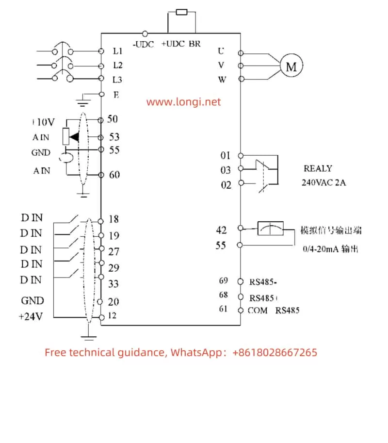
To achieve motor forward/reverse control, users need to connect external control signals to the digital input terminals of the converter. Typically, terminals 18 and 19 are used to control motor forward and reverse, respectively. The specific wiring method is as follows:
- Forward: Connect the external control signal to terminal 18 (DI1) and the common terminal (COM).
- Reverse: Connect the external control signal to terminal 19 (DI2) and the common terminal (COM).
Additionally, set the functions of terminals 18 and 19 to “Start” and “Reverse” in parameters 5-10 and 5-11, respectively. Also, set the motor rotation direction to “Bidirectional” in parameter 4-10.
External Potentiometer Speed Regulation
External potentiometer speed regulation is a commonly used speed control method. Users can change the motor speed by rotating the potentiometer. The specific wiring method is as follows:
- Connect one end of the external potentiometer to the +10V power terminal of the converter (e.g., terminal 50).
- Connect the other end of the external potentiometer to the analog input terminal of the converter (e.g., terminal 53) and ground (GND).
Then, select “Voltage Signal” as the input signal type for terminal 53 in parameter 6-19, and set the source of Reference Value 1 to “LCP Potentiometer” in parameter 3-15. By rotating the external potentiometer, users can adjust the motor speed in real-time.

III. Fault Codes and Their Solutions
The HOLIP HLP-SV series frequency converter has comprehensive protection functions. When a fault occurs, the converter will display the corresponding fault code. The following are some common fault codes, their meanings, and solutions:
- W/A 2: Signal Float Zero Fault
- Meaning: This fault occurs when the converter detects that the float zero value of terminal 53 or 60 is less than 50% of the set value.
- Solution: Check if the signal line connection is normal and ensure a stable signal source.
- W/A 4: Power Phase Loss
- Meaning: There is a phase loss or excessive voltage imbalance at the power supply terminal.
- Solution: Check the power input line and power supply voltage for normalcy.
- W/A 7: Overvoltage
- Meaning: The intermediate circuit voltage (DC) exceeds the converter’s overvoltage limit.
- Solution: Check if the power supply voltage is too high, connect a braking resistor, or activate “Braking Function/Overvoltage Control” in parameter group 2.
- W/A 9: Converter Overload
- Meaning: The converter’s electronic thermal protection indicates that the converter is about to disconnect due to overload.
- Solution: Check if the mechanical system is overloaded, adjust the load, or increase the converter capacity.
- W/A 10: Motor Overheat
- Meaning: The electronic thermal relay (ETR) protection device indicates motor overheat.
- Solution: Check the motor load and motor parameter settings for correctness, reduce the load, or improve the cooling conditions.
- A 16: Output Short Circuit
- Meaning: There is a short circuit in the motor terminal or motor.
- Solution: Check if the motor insulation is damaged and eliminate the short circuit fault.
The above are only some fault codes and their solutions. Users can refer to the fault code table in the converter user manual for troubleshooting other faults encountered during use.
IV. Conclusion
The HOLIP HLP-SV series user manual provides detailed operation guides and troubleshooting methods for users. By familiarizing with the functions of the operation panel and parameter setting methods, users can easily initialize the converter, set passwords, restrict parameter access, achieve forward/reverse control and external potentiometer speed regulation, and more. At the same time, understanding common fault codes and their solutions helps users quickly troubleshoot and resolve converter faults, ensuring normal equipment operation.
