
I. Introduction to the Operation Panel Functions and Initialization Settings
The Colran Inverter CV800 series features an intuitive operation panel with clear buttons and a display screen, facilitating various settings and monitoring tasks for users. The operation panel primarily includes run/stop keys, frequency adjustment keys (▲/▼), function keys, and a display screen.
Parameter Initialization:
- Press the function key to enter the parameter setting interface.
- Use the ▲/▼ keys to select the F8.03 parameter (Parameter Initialization).
- Press the run/stop key to set F8.03 to 1, which will restore the factory settings, and all user parameters will be reset to their factory defaults.
Setting and Removing Password:
- Password Setting: Set through the F0.23 parameter (User Password). Set any non-zero number, which will take effect after waiting for 3 minutes or a power cycle.
- Password Removal: Set the F0.23 parameter value to 0 to remove the password.
Setting Parameter Access Restrictions:
- The CV800 series inverters provide parameter access restriction functions, but the specific implementation method is not explicitly mentioned in the manual. Generally speaking, parameter access restrictions can be indirectly achieved by setting a password, allowing only users who know the password to modify critical parameters.
II. Terminal Forward/Reverse Control and External Potentiometer Given Frequency Speed Regulation
Terminal Forward/Reverse Control:
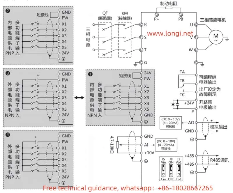
- Wiring:
- Connect the forward control signal to the X1 terminal (Forward Control, FWD).
- Connect the reverse control signal to the X2 terminal (Reverse Control, REV).
- Ensure the common terminal (COM) is correctly connected.
- Parameter Setting:
- Set F0.02 parameter (Operation Command Channel Selection) to 1 (Terminal Operation Command Channel).
- Set F2.13 parameter (Input Terminal X1 Function) to 3 (Forward Control).
- Set F2.14 parameter (Input Terminal X2 Function) to 4 (Reverse Control).
External Potentiometer Given Frequency Speed Regulation:
- Wiring:
- Connect the output terminal of the external potentiometer to the AI terminal (Analog Input).
- Ensure the common terminal (COM) is correctly connected.
- Parameter Setting:
- Set F0.03 parameter (Frequency Given Selection) to 0 (Panel Potentiometer) or 3 (AI Analog Given).
- Set F2.00 (AI Input Lower Limit Voltage) and F2.01 (AI Input Upper Limit Voltage) as needed.
- F2.02 (AI Lower Limit Correspondence Setting) and F2.03 (AI Upper Limit Correspondence Setting) are used to set the correspondence between AI input and output frequency.
III. Fault Codes and Solutions
The CV800 series inverters provide a wealth of fault codes to help users quickly locate and resolve issues. Below are some common fault codes, their meanings, and solutions:
- E0C1: Overcurrent During Acceleration.
- Meaning: The current during acceleration exceeds the allowable limit.
- Solution: Extend the acceleration time, check if the load is too heavy, or select an inverter with higher power.
- E0C2: Overcurrent During Deceleration.
- Meaning: The current during deceleration exceeds the allowable limit.
- Solution: Extend the deceleration time and check for sudden load changes.
- EHU1: Overvoltage During Acceleration.
- Meaning: The voltage during acceleration exceeds the allowable limit.
- Solution: Check for abnormal input power or set the DC braking function.
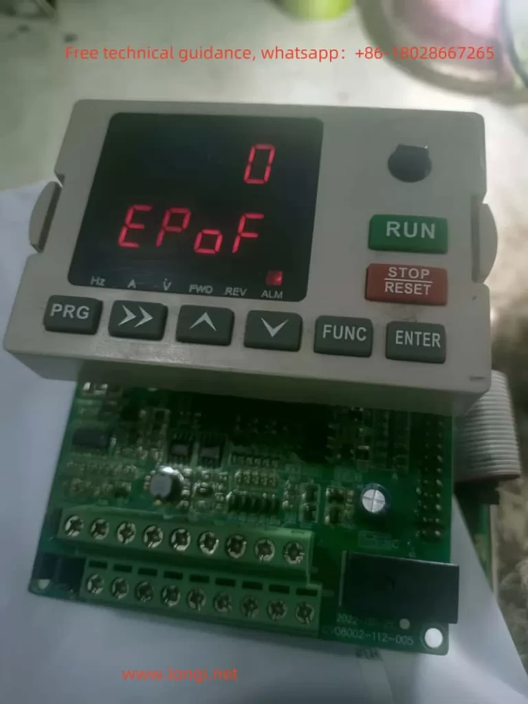
- EPOF: Dual CPU Communication Fault.
- Meaning: Internal CPU communication within the inverter is abnormal.
- Solution: Restart the inverter. If the problem persists, contact the manufacturer for repair.
- E-OH: Heatsink Overheated.
- Meaning: The temperature of the inverter’s heatsink is too high.
- Solution: Check if the ambient temperature is too high, clean the air duct, or replace the fan.
IV. Conclusion
The Colran Inverter CV800 series, with its rich functionality and stable performance, has found widespread application in the industrial automation field. This operation guide enables users to easily master the basic operation, parameter settings, terminal wiring, and troubleshooting methods of the inverter, ensuring its normal operation and efficient use. Meanwhile, users should regularly check the working status of the inverter, promptly detect and resolve issues to guarantee the continuous and stable operation of the production line. In practical applications, users should also perform personalized settings based on specific needs to fully leverage the performance advantages of the inverter.