
Introduction
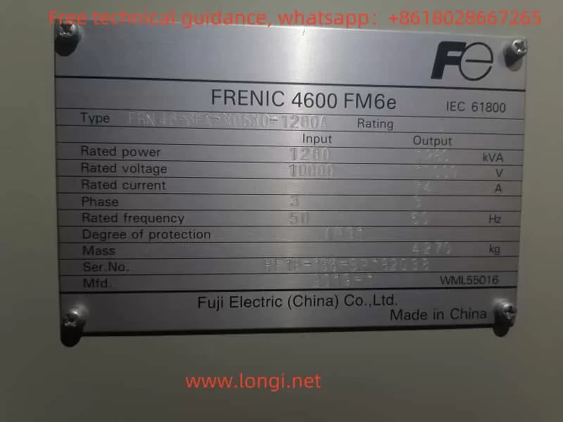
The FRENIC4600FM6e series high voltage inverter from Fuji Electric is a device specifically designed to drive high-voltage motors, widely used in various industrial applications such as water pumps, fans, compressors, and more. This inverter not only provides efficient motor control but also offers a wealth of features and flexible configuration options. To ensure users can fully utilize the inverter’s functions, it is essential to understand and operate the user manual correctly. This article provides a detailed guide to using the FRENIC4600FM6e Series Inverter User Manual, covering wiring, parameter settings, control modes, fault diagnostics, parameter backups, and more, helping users operate and maintain the device more effectively.
1. Inverter Wiring Guide
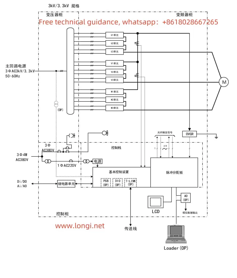
Wiring the inverter correctly is fundamental to ensuring its proper operation. For the FRENIC4600FM6e Series, users need to properly connect the power supply, motor, and various control terminals. The following are key points for wiring:
- Power Input: The inverter requires a three-phase high voltage input, commonly 3φAC 3.0kV, 3.3kV, 6kV, etc. When connecting the power supply, users must ensure that the input voltage matches the inverter’s rated voltage.
- Motor Connection: The inverter outputs three-phase voltage to the motor terminals U, V, and W, driving the motor. When wiring, it is important to ensure that the motor’s rated voltage matches the inverter’s output voltage.
- Control Terminals:
- DI Terminals (Digital Input): Used for control signals such as start/stop, forward/reverse, etc.
- DO Terminals (Digital Output): Outputs operational status, fault information, and more.
- AI Terminals (Analog Input): Used for analog frequency command input signals.
- AO Terminals (Analog Output): Outputs analog frequency, current, and other data.
When wiring, ensure all terminals are securely connected, and pay attention to the specific function of each terminal to avoid miswiring, which could lead to device failure.
2. Parameter Settings and Initialization
- Basic Parameter Settings
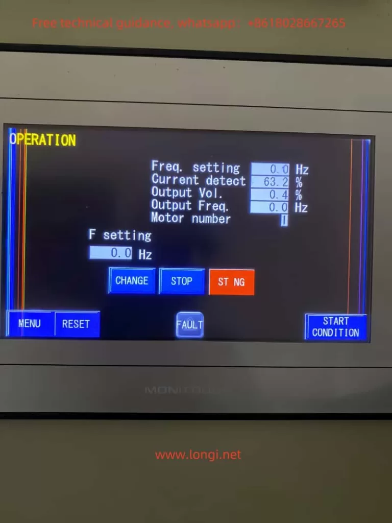
- No.1~12: Set operating frequency, output voltage, and other parameters. Users can adjust these settings based on the motor and load requirements to ensure the device operates under optimal conditions.
- No.28~40: Set acceleration and deceleration times, determining the smoothness of motor start and stop.
- No.173: Set the function of external terminals (such as DI terminals) for start/stop, forward/reverse, and other control signals.
- Initialization Settings The FRENIC4600FM6e Series offers a factory reset function. Users can restore the inverter to its default settings using No.200, which resets the inverter’s parameters to their factory default configuration. This operation is useful when resetting parameters or correcting configuration errors.
- Parameter Backup Before performing initialization or other operations, it is advisable to back up the parameters to prevent losing important custom configurations. Users can back up and restore the parameter settings using Loader software. The steps are as follows:
- Connect Loader to the inverter.
- In Loader, select the option to back up current settings.
- Choose a file location for storing the backup file. The backup file can be saved on a computer and used for future recovery operations.
- To restore the parameters, load the backup file and restore the previous configuration.
3. Control Modes and Password Settings
The FRENIC4600FM6e supports multiple control modes, including panel control and external terminal control. Users can select the appropriate control mode based on their needs.
- Panel Control vs. External Terminal Control
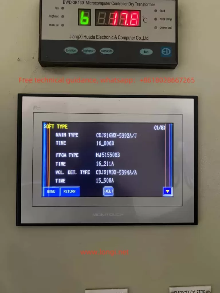
- Panel Control: Users can directly set frequency, start/stop the motor, and more via the LCD panel.
- External Terminal Control: Through DI terminals, external control signals can start or stop the inverter. Users need to configure the terminal functions via No.173 to ensure proper signal transmission.
- Password Protection and Parameter Access Restrictions To prevent unauthorized operations, the inverter supports password protection and parameter access restrictions:
- No.12: Set administrator and user passwords. Different passwords provide different access levels—administrators can modify all parameters, while users are restricted.
- No.13~14: Set parameter access restrictions, preventing critical parameters from being accidentally changed or modified by unauthorized personnel.
By using password protection and access restrictions, users can effectively safeguard the operation and configuration of the inverter, preventing operational errors or unauthorized modifications.
4. Fault Diagnostics and Solutions
During operation of the FRENIC4600FM6e Series, users may encounter various faults. The inverter provides LCD panel or fault codes to offer fault information, helping users quickly locate the problem.
- Common Fault Codes and Solutions:
- E.F. Overload Fault: Check if the motor load is too high. Avoid overload conditions.
- E.U. Phase Loss Fault: Check the power supply wiring to ensure there is no missing phase.
- E.O. High Voltage Fault: Adjust the output voltage settings and check for motor problems.
- E.C. Low Battery Voltage: Replace the internal battery of the inverter.
- E.P. Over Temperature Fault: Check if the cooling system is working properly and clean the heat sinks.
- Troubleshooting Steps:
- Check Power Supply and Cables: Ensure the power supply is stable, and the cable connections are secure and undamaged.
- Check Motor Load: Ensure the motor load does not exceed the rated capacity.
- Check Cooling System: Clean fans and heat sinks regularly to ensure the inverter operates within the appropriate temperature range.
5. Summary
The FRENIC4600FM6e High Voltage Inverter is a high-performance motor control device equipped with various features such as parameter settings, control modes, password protection, fault diagnostics, and more. By understanding and correctly operating the functions outlined in the user manual, users can effectively configure, operate, and maintain the device. Whether backing up parameters using Loader, setting password protection, diagnosing faults, or configuring control modes, making proper use of these functions ensures long-term stable operation, improved efficiency, and enhanced safety.
This guide aims to help users better understand and use the FRENIC4600FM6e Series Inverter, maximizing its performance advantages in real-world applications.