
The TECO GS510 series inverter is a high-performance variable frequency drive widely used in industrial automation, ventilation systems, pump equipment, and other fields. This article provides a detailed introduction to the operation panel functions of the GS510 series inverter, parameter initialization, encryption and decryption, parameter access restrictions, external terminal forward and reverse control, external potentiometer speed regulation, fault codes, and their meanings and solutions. Through this article, users can better understand the operation methods of the GS510 inverter, improve equipment utilization efficiency, and reliability.
I. Operation Panel Function Introduction
1. Operation Panel Overview
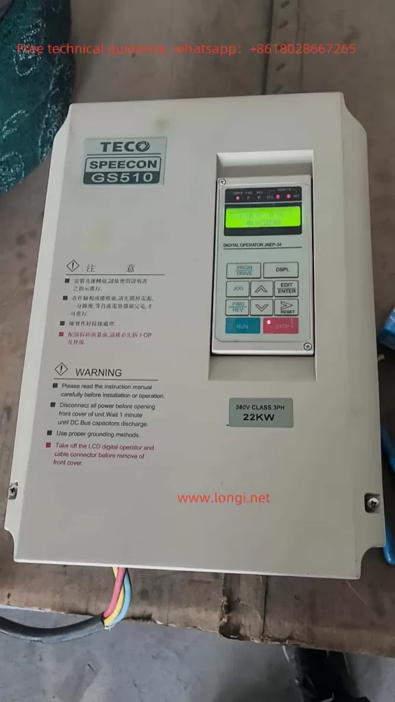
The operation panel of the GS510 inverter mainly includes a digital operator and multifunctional terminals. The digital operator comes in two types: LCD display (JNEP-34) and LED display (JNEP-33). Users can choose according to their needs. The main functions of the operation panel include parameter setting, operation control, and fault display.
2. Parameter Initialization
- Implementation Method:
By setting the parameter Sn-03 to 1110 or 1111, most parameters of the inverter can be restored to the factory default settings. - Steps:
- Enter PRGM mode.
- Select the parameter Sn-03 and set the value to 1110 or 1111.
- After confirmation, the inverter will automatically initialize the parameters.
- Note: After initialization, the parameters Sn-01, Sn-02, Sn-13, and Sn-23 will not be reset.
3. Encryption and Decryption
- Encryption Function:
The GS510 inverter supports parameter encryption to prevent unauthorized personnel from arbitrarily modifying parameters. - Encryption Method:
- Enter PRGM mode.
- Set the parameter Sn-00 to the password value (e.g., 1234).
- After confirmation, the inverter enters the encrypted state.
- Decryption Method:
- Enter PRGM mode.
- Enter the password value (e.g., 1234).
- After confirmation, the inverter exits the encrypted state.
4. Parameter Access Restriction Settings
- Access Restrictions:
By setting the parameter Sn-03, the access rights of parameters in different modes can be restricted. - DRIVE Mode:
- Sn-03 = 0000: An, bn parameters can be set, Sn, Cn parameters can only be viewed.
- Sn-03 = 0101: Only An parameters can be set, other parameters can only be viewed.
- PRGM Mode:
- Sn-03 = 0000: All parameters can be set.
- Sn-03 = 0101: Only An parameters can be set, other parameters can only be viewed.
II. External Terminal Control
1. External Terminal Forward and Reverse Control
- Terminal Connection:
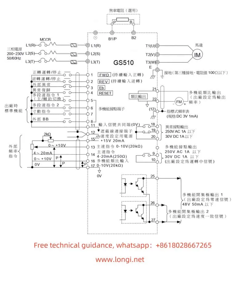
External forward and reverse control requires the use of control circuit terminals 1 (forward) and 2 (reverse). - Wiring Method:
- Connect the forward control signal to terminal 1.
- Connect the reverse control signal to terminal 2.
- Parameter Settings:
- Set the second bit of parameter Sn-05 to 0, indicating acceptance of external terminal control.
- Set the first bit of parameter Sn-03 to 0, indicating that the frequency command comes from the control circuit terminal.
2. External Potentiometer Speed Regulation
- Terminal Connection:
External potentiometer speed regulation requires the use of control circuit terminals 13 (voltage type) or 14 (current type). - Wiring Method:
- Connect the output signal of the potentiometer to terminal 13 (voltage type) or 14 (current type).
- Ensure that the output range of the potentiometer matches the input range of the inverter.
- Parameter Settings:
- Set the first bit of parameter Sn-03 to 0, indicating that the frequency command comes from the control circuit terminal.
- Set parameter bn-05 to the gain value of the potentiometer, and bn-06 to the offset value of the potentiometer.
III. Fault Codes and Solutions
1. Meaning of Fault Codes
The GS510 inverter displays fault codes through the digital operator to help users quickly identify problems. The following are common fault codes and their meanings:
| Fault Code | Meaning |
|---|---|
| OV | Overvoltage fault, main circuit DC voltage exceeds 820V (440V level). |
| UV | Undervoltage fault, main circuit DC voltage below 380V (440V level). |
| OL1 | Overload fault, output current exceeds 150% of the rated current. |
| OC | Overcurrent fault, output current exceeds 200% of the rated current. |
| OH | Overheating fault, internal temperature of the inverter is too high. |
| GF | Ground fault, electronic circuit detects ground current. |
2. Fault Handling Methods
- Overvoltage (OV) / Undervoltage (UV):
Check if the input voltage is normal and ensure the stability of the power supply. - Overload (OL1) / Overcurrent (OC):
Check if the load exceeds the rated capacity of the inverter. Reduce the load or replace it with a suitable inverter if necessary. - Overheating (OH):
Check the heat dissipation conditions of the inverter and ensure good ventilation. Install a cooling fan if necessary. - Ground Fault (GF):
Check if the ground wire is correctly connected and ensure that the inverter and motor are grounded separately.
IV. Conclusion
The TECO GS510 series inverter is a powerful and flexible variable frequency drive. By reasonably setting parameters and correctly wiring, various control methods can be realized to meet the needs of different application scenarios. This article provides a detailed introduction to the operation panel functions, parameter initialization, encryption and decryption, parameter access restriction settings, external terminal control, and fault handling methods of the GS510 inverter. It aims to help users better understand the operation methods of the GS510 inverter, improve equipment operation efficiency and reliability. It is hoped that this article will provide valuable reference for users and contribute to the efficient operation of the equipment.