
After checking the drive circuit of the 22kW Delta VFD Drive and replacing it with a new module, the OC will jump upon startup. The module is newly replaced, and all six drive pulses are working properly. I don’t think it should be. Still checking the measurement, the six negative pressures driving the IC during shutdown are all normal, and the six excitation voltages are also normal after startup. It is necessary to first determine whether the fault is caused by the driver IC or the module.
It is necessary to first test the load carrying capacity of the six drive ICs, that is, to measure the trigger current value of their output. Connect a 15 ohm resistor in series to the output terminal, and then connect a 15 ohm resistor in series to the probe to limit the circuit current to around 0.5A. After the start signal is activated, its current output capacity is measured, and it can still provide a dynamic current of about 150mA even when the original trigger circuit is connected normally. The driving circuit of the V-phase lower arm IGBT tube only outputs about 40mA of current, which obviously cannot meet the excitation requirements of the IGBT tube. The root cause of the OC fault lies in this!
There seems to be a misconception about the driving method of IGBT tubes, especially high-power IGBT tubes: IGBT tubes are voltage signal excitation devices, not current type excitation devices. The driving signal only needs to meet the voltage amplitude, without requiring too much current driving capability! I have previously analyzed that even IGBT tubes are essentially current driven devices!
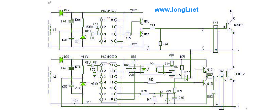
The output signals of the driving ICs (PC929 and PC923) of the machine are amplified by a complementary voltage follower and then supplied to the triggering terminals of the module. The push-pull amplifier was originally a pair of field-effect transistors, but due to the lack of the original type of transistor on hand, it has now been replaced with transistor pairs D1899 and B1261. After modification testing, it should be able to meet the excitation requirements. Check the V-phase lower arm circuit. The resistance from pin 11 (pulse output pin) of PC929 to the subsequent power amplifier circuit was originally 100 ohms, but now it has changed to over 100k, causing D1899 to be unable to fully conduct and the output driving current to be too small. After replacing the resistor, the output current is normal. After replacing the power transistor, the base resistance was not measured, resulting in this phenomenon.
By the way, I measured the negative current supply capacity of the driving circuit when cutting off negative pressure output. The probe is still connected in series with a 15 ohm resistor, and each circuit is around 30mA.
This leads to the conclusion that measuring the output voltage of the driving IC is not as direct and effective as measuring its output current. And it can expose the root cause of the malfunction. When the internal resistance of the circuit output increases due to certain reasons, measuring the driving voltage is often normal, which masks the truth of insufficient driving current.