
The SZOR ZC1000 Series AC Drive is a high-performance variable frequency control device widely used in various industrial automation control systems. This article provides a detailed introduction to the operation panel functions, parameter settings, and troubleshooting for the ZC1000 Series, helping users better understand and utilize this equipment.
I. Introduction to Operation Panel Functions
1.1 Overview of Operation Panel Functions
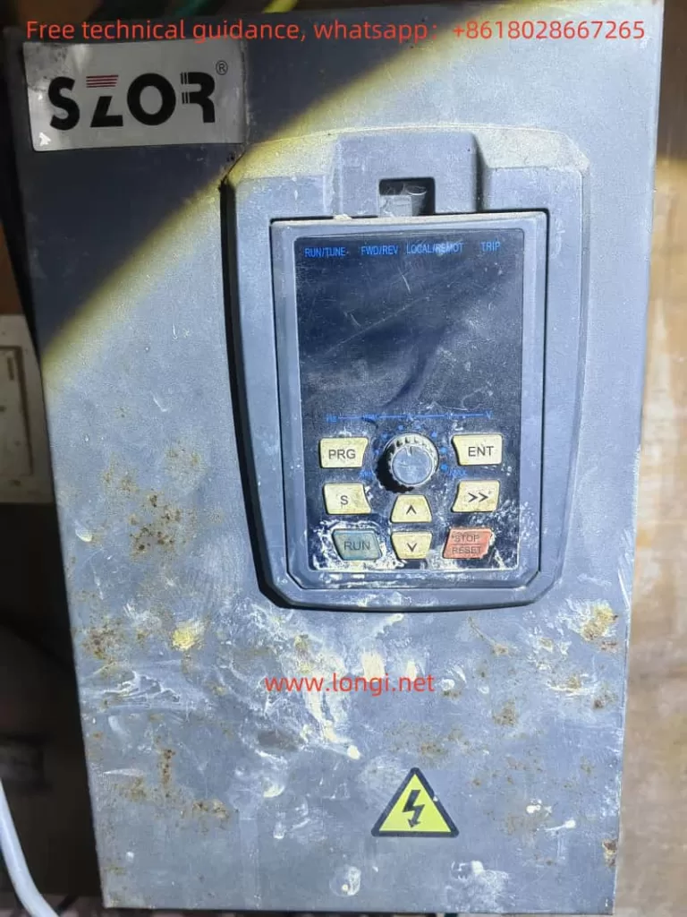
The operation panel of the ZC1000 Series AC Drive is the primary interface for user interaction with the device. Through the operation panel, users can control the drive’s operating status, read status data, and adjust parameters. The operation panel mainly includes the following parts:
- Status Indicator Lights: Indicate the drive’s running status, fault status, etc.
- Unit Indicator Lights: Display the current unit, such as frequency (Hz), current (A), voltage (V), etc.
- Code Display Area: Displays various monitoring data and alarm codes.
- Analog Potentiometer: Used to set the frequency when the frequency source is set to the analog potentiometer.
- Keypad Button Area: Includes program keys, entry keys, up/down keys, right shift keys, run keys, stop/reset keys, etc., used for operating the drive and modifying parameters.
1.2 Parameter Copying
To copy parameters from one drive to another, follow these steps:
- Upload Parameters to Keypad EEPROM: On the source drive, set F08.29 to 1 to upload control panel parameters to the keypad EEPROM.
- Download Parameters to Target Drive: On the target drive, set F08.29 to 2 or 3 to download parameters from the keypad EEPROM to the control panel, and choose whether to download motor parameters.
1.3 Parameter Initialization
Parameter initialization restores the drive’s parameters to factory settings. Follow these steps:
- Enter Parameter Setting Interface: Press the “PRG” key to enter the parameter setting interface.
- Select Parameter Initialization Option: Locate parameter F00.18 and set it to 1 to restore default values.
- Confirm and Save: Press the “ENT” key to confirm and save the parameters.
1.4 Setting and Removing Passwords
To protect the drive’s parameters from unauthorized access, you can set a password:
- Set Password: In the parameter setting interface, locate parameter F07.00 and set it to a non-zero value to set the password.
- Remove Password: Set parameter F07.00 to 0 to remove the password.
1.5 Parameter Access Restrictions
To further protect the drive’s parameters, you can set parameter access restrictions:
- Set Parameter Access Restrictions: In the parameter setting interface, locate parameter F08.21 and set it to 0x0000 to restrict parameter access.
- Remove Parameter Access Restrictions: Set parameter F08.21 to another value to remove access restrictions.
II. External Terminal Forward/Reverse Control and External Potentiometer Speed Control
2.1 External Terminal Forward/Reverse Control
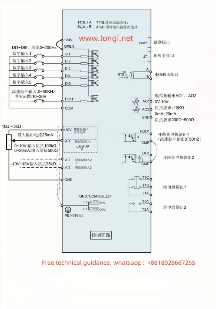
External terminal forward/reverse control allows the use of external switches or buttons to control the drive’s forward/reverse operation. The wiring and parameter settings are as follows:
- Wiring: Connect the external switch or button to the drive’s DI1 terminal (forward) and DI2 terminal (reverse).
- Parameter Settings: In the parameter setting interface, locate parameter F05.01 and set it to 1 (forward) or 2 (reverse).
2.2 External Potentiometer Speed Control
External potentiometer speed control allows the use of an external potentiometer to set the drive’s frequency. The wiring and parameter settings are as follows:
- Wiring: Connect the external potentiometer to the drive’s Al1 terminal.
- Parameter Settings: In the parameter setting interface, locate parameter F00.06 and set it to 2 (analog Al1 setting).
III. Fault Codes and Troubleshooting
The ZC1000 Series AC Drive may encounter various faults during operation. Fault codes help quickly identify the cause and address the issue. Below are some common fault codes and their meanings, along with troubleshooting steps:
3.1 Common Fault Codes
- E.out 1/2/3: IGBT U/V/W phase protection fault, possibly due to fast acceleration, internal IGBT damage, or poor driving wire connections. Solutions include increasing acceleration time, replacing the power unit, and checking driving wires.
- E.oc 1/2/3: Acceleration overcurrent fault, possibly due to fast acceleration/deceleration, low grid voltage, or insufficient drive power. Solutions include increasing acceleration time, checking input power, and selecting a larger drive.
- E.ou 1/2/3: Acceleration or constant overvoltage fault, possibly due to abnormal input voltage or large energy feedback. Solutions include checking input power and increasing energy consumption components.
- E.LU: Bus undervoltage fault, possibly due to low supply voltage. Solution: Check the input power supply.
- E.SPI: Input phase loss fault, possibly due to input phase loss or fluctuation. Solution: Check the input power supply.
3.2 Troubleshooting Steps
- Confirm Fault Code: Use the code display area on the operation panel to confirm the fault code.
- Identify Fault Cause: Refer to the fault code to identify possible causes.
- Take Action: Based on the fault cause, take appropriate actions such as checking power supply, replacing components, or adjusting parameters.
- Restart the Drive: After addressing the fault, restart the drive to ensure the issue is resolved.
Conclusion
The SZOR ZC1000 Series AC Drive is a powerful and user-friendly variable frequency control device. This guide provides insights into the operation panel functions, parameter settings, and troubleshooting for the ZC1000 Series. By understanding these aspects, users can effectively utilize the ZC1000 Series AC Drive, enhancing work efficiency and prolonging the device’s lifespan.