
1. Fault Overview
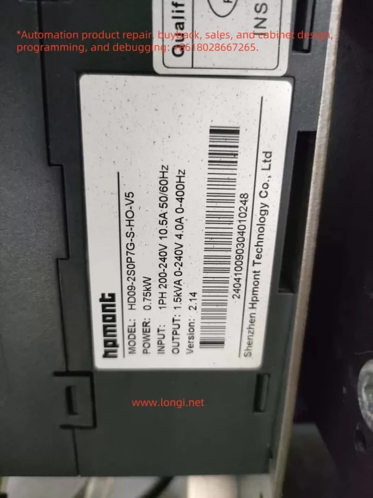
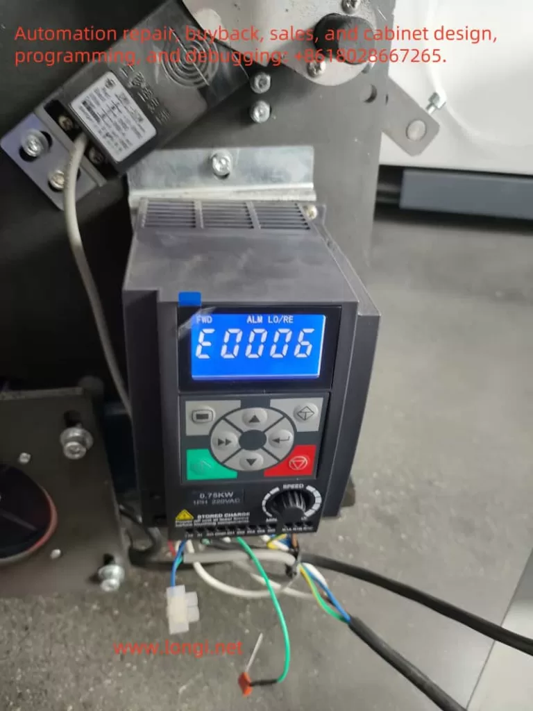
The E0006 fault in the HPMONT HD09 series inverter corresponds to a “DC bus constant-speed overvoltage fault.” This means that the DC bus voltage in the inverter exceeds the safety limit during constant-speed operation. Such faults can cause equipment shutdowns, affecting production and normal operation.
2. Fault Mechanism Analysis
- Causes of DC Bus Overvoltage: The DC bus voltage in the inverter is converted from AC through a rectifier. If the input voltage is too high or too low, it can cause instability in the bus voltage. During load operation, especially during rapid stops, large load inertia, or abnormal braking systems, the DC bus voltage may rise sharply, triggering overvoltage protection.
- Constant-Speed Overvoltage Scenario: The inverter operates at a constant speed, maintaining a stable motor frequency. If the input power supply voltage is too high, or if the acceleration/deceleration times are improperly set, overvoltage can occur. Furthermore, if the braking system is improperly configured or not correctly installed, excessive voltage can be generated during deceleration.
- Potential Circuit Reasons:
- High input voltage: Especially in areas where the grid voltage fluctuates significantly, the inverter may detect overvoltage.
- Abnormal braking system: If the braking unit or brake resistor is incorrectly configured, or if it is not equipped in systems with heavy loads, excessive voltage can be generated during deceleration.
- System overload: If the load is too heavy or has significant inertia, the inverter may not be able to decelerate effectively, leading to overvoltage faults.
3. On-Site Fault Handling Methods
- Check Input Voltage:
- Use a multimeter to check whether the input voltage to the inverter is within the normal range. If the input voltage exceeds the specified range (e.g., too high), consider using a voltage regulator or check the stability of the power grid.
- Check Acceleration/Deceleration Time Settings:
- Refer to the inverter’s user manual and check the acceleration and deceleration times (parameters such as F03.01, F03.02, etc.). Too short a deceleration time can cause a sharp fluctuation in the bus voltage. It is recommended to extend the deceleration time to avoid overvoltage.
- Check Braking System:
- For loads requiring deceleration, inspect the braking unit and brake resistor configuration to ensure they are appropriately sized for the load. If necessary, add a braking unit or adjust the brake resistor’s power and resistance.
- Inspect and Check the Circuit:
- Inspect the internal circuitry of the inverter for loose connections, poor contact, or damage, especially in the power and braking resistor wiring terminals.
4. Specific Circuit Repair Methods
- Input Voltage Issues:
- If the input voltage is too high, consider adding measures to stabilize the grid power, such as using overvoltage protection devices. For areas with significant voltage fluctuations, it is recommended to use appropriate power protection equipment, such as overvoltage protectors.
- Braking System Faults:
- If the braking system is causing overvoltage, first verify whether the braking resistor is correctly specified. If the braking resistor is inadequate or damaged, select a properly rated resistor according to the load requirements. Check that the braking unit is properly connected, and ensure the braking circuit is securely wired.
- Capacitor Issues:
- If the capacitor is aging or damaged, it could cause the DC bus voltage to be unstable. In this case, replace the damaged capacitors and verify whether the capacitor’s capacity matches the requirements.
- Reconfigure Deceleration Time:
- For loads with high inertia or large power, it is necessary to increase the deceleration time. This can be achieved by adjusting parameters such as F03.02 to prevent overvoltage faults. Ensure that the deceleration process is smooth and does not lead to a sharp voltage change.
5. Conclusion
The E0006 fault is typically caused by high input voltage, braking system issues, or improper acceleration/deceleration time settings. When addressing this fault, it is essential to check key parameters such as input voltage, acceleration/deceleration times, and the braking system. Specific circuit repair actions, such as replacing capacitors, adjusting the braking system configuration, and extending deceleration times, can restore normal operation of the inverter.