
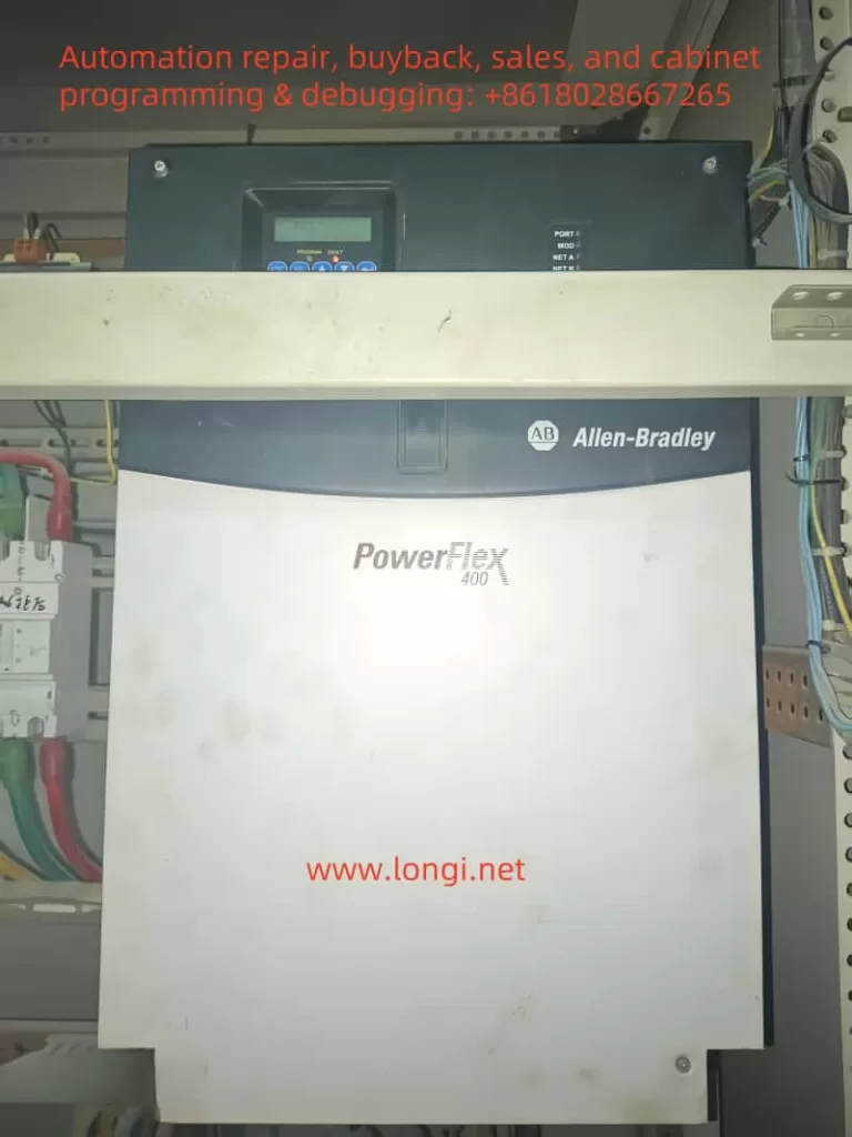
The Rockwell (Allen-Bradley) PowerFlex 400 series inverter is a widely used, high-performance device in industrial automation, valued for its stability and reliability. However, during prolonged operation, it may encounter faults, one of which is the F 032 fault, known as Fan Feedback Loss. This article analyzes this fault in detail—its meaning, causes, on-site troubleshooting steps, and repair methods—offering clear guidance for field engineers to restore equipment operation efficiently.
What the F 032 Fault Means and Why It Happens
Meaning of the Fault
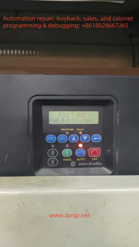
The F 032 fault code indicates Fan Feedback Loss, a common issue in Frame E and F models (higher power units) of the PowerFlex 400 series. These models feature a cooling fan feedback monitoring system. When the inverter cannot detect the fan’s normal operation, it triggers this fault and shuts down to prevent overheating damage.
How It Occurs
The inverter generates significant heat during power conversion, and the cooling fan is essential to keep internal components (like IGBT modules and capacitors) at safe temperatures. In Frame E and F models, the fan sends a feedback signal to the inverter’s control system to confirm it’s working. If this signal is lost—due to fan failure, wiring issues, or control circuit problems—the F 032 fault is activated.
Possible Causes:
- Fan Mechanical Failure: Blocked blades, damaged motor, or seized bearings.
- Power/Circuit Problems: Open or short circuits, or loose power supply connections.
- Feedback Signal Issues: Disconnected, broken, or faulty signal lines or control board circuits.
- Environmental Factors: Excessive heat or dust affecting fan performance.
Why It Matters
The F 032 fault is a self-protection mechanism. Without proper cooling, sensitive components could overheat, leading to equipment failure. By stopping operation, the inverter prevents damage, prioritizing long-term reliability over temporary production continuity.
On-Site Troubleshooting Steps
When an F 032 fault appears, follow these steps to diagnose and fix it quickly, minimizing downtime:
- Check Fan Operation
- Action: Power off the inverter, open the panel, and check if the fan spins.
- Steps: Remove dust or debris from blades; manually spin the fan to detect jams or resistance.
- Goal: Rule out mechanical issues.
- Inspect Power and Control Circuits
- Action: Examine the fan’s power and signal line connections.
- Steps: Use a multimeter to verify voltage at the fan’s power terminal; check for circuit breaks or shorts.
- Goal: Ensure power delivery isn’t the issue.
- Verify Feedback Signal Lines
- Action: Check the connection between the fan’s feedback line and the control board.
- Steps: Confirm the line isn’t loose or broken; test continuity with a multimeter if possible.
- Goal: Fix signal transmission problems.
- Reset and Test
- Action: Reset the fault via the panel’s “FAULT RESET” button or programming mode.
- Steps: Restart the inverter and monitor if the fault recurs; continue operation if cleared.
- Goal: Confirm if it was a temporary glitch.
- Review Parameter Settings
- Action: Access programming mode to check fan monitoring parameters (e.g., P040).
- Steps: Verify the function is enabled and settings are correct.
- Goal: Eliminate false alarms from misconfiguration.
- Assess Environmental Conditions
- Action: Evaluate the inverter’s surroundings.
- Steps: Clean the heat sink; ensure ambient temperature is within 0-50°C.
- Goal: Address environmental triggers.
Most F 032 faults can be resolved with these steps. If the issue persists, deeper repairs are needed.
Repair Methods When On-Site Fixes Fail
If troubleshooting doesn’t work, the problem may involve hardware damage. Here’s how to proceed:
- Disassemble the Inverter
- Action: Power off, discharge residual voltage, and remove the casing.
- Tips: Follow safety protocols; note disassembly steps for reassembly.
- Tools: Screwdriver, multimeter.
- Examine Fan and Circuits
- Action: Inspect the fan, power lines, control lines, and feedback lines.
- Steps: Test power supply voltage; look for burns or breaks in circuits.
- Fix: Repair or replace damaged parts; test the fan next if power is fine.
- Test the Fan Independently
- Action: Connect the fan to a separate power source.
- Steps: Check if it spins; replace it if it doesn’t (use a matching model).
- Tips: Ensure compatibility with the original fan.
- Check the Control Board
- Action: Inspect the main control board or fan control circuit.
- Steps:
- Look for burned components or loose solder joints.
- Test feedback signal input with a multimeter.
- Identify issues like damaged chips or connectors.
- Fix: Re-solder joints; replace faulty components; consider board replacement if damage is severe.
- Reassemble and Verify
- Action: Reassemble, power on, and test.
- Steps: Confirm fan operation and fault clearance; monitor cooling performance.
- Goal: Ensure the repair worked.
Preventing Future F 032 Faults
To minimize recurrence:
- Routine Cleaning: Clear dust from the inverter and fan every three months.
- Wiring Checks: Regularly inspect power and signal line connections.
- Ventilation: Keep the installation area well-ventilated and within temperature limits.
Conclusion
The F 032 fault in the PowerFlex 400 series inverter is a vital alert tied to fan failure, designed to prevent overheating damage. By understanding its causes and following structured on-site troubleshooting, engineers can often resolve it quickly. For persistent issues, detailed repairs targeting the fan or control board are effective. Combined with preventive maintenance, these steps ensure equipment reliability and support uninterrupted industrial operations.