
M900 Inverter err64 Fault: Meaning, Root Cause Analysis, and Solutions
(This article discusses the background of the “err64” fault in M900 series inverters, its potential causes, deeper hardware-level analyses, and practical troubleshooting steps. The goal is to help electrical maintenance personnel target the problem more effectively. This text, of over 1,000 words in its Chinese original, covers both theoretical and hands-on repair perspectives.)
-
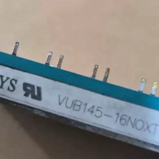
VUB145-16NOXT Power Module for ABB ACS850 Series, Genuine Disassembled, Quality Assured
$250.00 Add to cart -
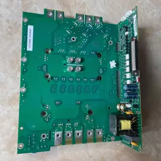
JSEM-D4C Drive Board 68965217F with Module FS150R12KT3 for ABB ACS850 Series, Genuine Disassembled, Quality Assured
$4,500.00 Add to cart -
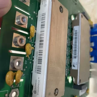
JSEM-D3C Drive & Power Board 68975743E with Modules DDB6U134N16RR and 6MBI100U4B-120-50 for ABB ACS850, Disassembled, Reliable Quality, Good Condition
$4,500.00 Add to cart -
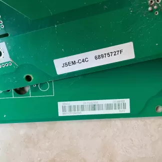
JSEM-C4C Drive Board 68975727F (Without Vertical Plate and Module) for ABB ACS850 Series, Genuine Disassembled, Quality Assured
$1,000.00 Add to cart -
JSEM-B2C Drive Board 68629624D with Infineon Module FS150R12KT3 for ABB ACS850, Genuine Disassembled, Quality Assured
$4,500.00 Add to cart -
INT-C1C Drive Board Vertical Mount for ABB ACS850 Series, Genuine Disassembled, Quality Assured
$1,800.00 Add to cart
I. Background and Meaning of err64
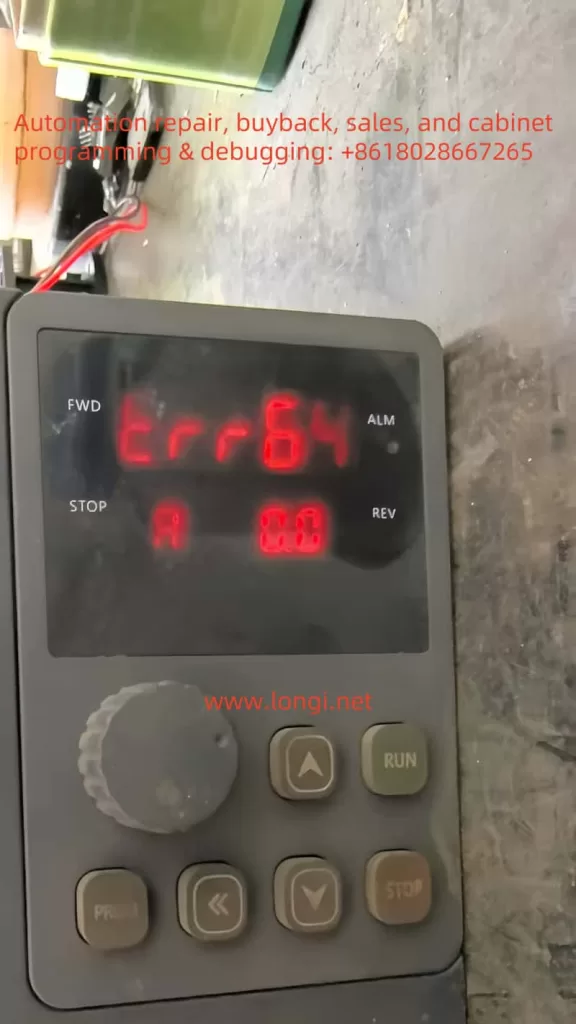
In typical inverter applications, the most common faults involve overcurrent, overvoltage, undervoltage, overload, and cooling fan issues. However, in certain cases—especially after repairs or the replacement of internal components—M900 inverters may display a “err64” fault code. According to the manufacturer’s technical support, “err64” is not listed in the usual user manual but indicates a communication failure between the main control board and the driver board.
In other words, the inverter’s primary control circuitry (often referred to as the “master” or “main” board) and its power drive unit (“driver” board) cannot exchange data, causing the control system to fail to operate properly and thus triggering a fault protection.
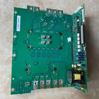
To understand this issue, one must note that an M900 inverter typically consists of at least two major sections: a control board (hosting the microcontroller or DSP as the core of the logic) and a driver board (housing the power modules, IGBTs, or related gate driver circuitry). These boards communicate via a dedicated interface or set of pins. Sometimes, there may also be a small power supply board or other auxiliary boards, but the communication link between the main board and the driver board is central to the entire system. Once that link is broken or corrupted, the inverter will report a “board-to-board communication error” such as “err64” and shut down to protect itself.
II. Common Causes of err64
- Loose or Faulty Ribbon Cable/Connector
During maintenance or reassembly, a ribbon cable or connector might not have been fully seated, or its metal pins could be bent, oxidized, or otherwise damaged. This often leads to poor signal transmission or no transmission at all, and is one of the most frequent root causes for communication errors. - Damaged Hardware Chips
- Burned-out Transceiver/Bus Chip: The communication between the control and driver boards usually involves specialized transceiver components (e.g., RS485 driver chips, optical isolators, or TTL level transceivers). If subjected to excessive heat, current surge, or electrostatic discharge, these chips can fail and interrupt the data link.
- Main CPU or Driver DSP Failure: Though less common, serious power surges, extended over-temperature conditions, or short-circuit mishandling can damage the main controller or DSP on either board. When that happens, the inverter can no longer exchange valid data, triggering the err64 alarm.
- Auxiliary Power Supply Issues
The main board and driver board typically rely on a regulated power supply—often +5V or +3.3V—to operate their digital circuits. If this low-voltage supply is weak or unstable, or if a regulator (LDO, DC-DC converter) on either board is failing, then even intact chips may produce garbled signals and fail to establish proper communication. - Secondary Damage During Fan or Relay Replacement
Many reported err64 errors occur soon after a user replaces a fan or relay. This suggests that the process may introduce secondary problems:- An incompatible relay or altered circuit parameters causing abnormal power conditions;
- Accidental short-circuits or soldering damage during the repair;
- The inverter may already be partially degraded from prior overheating, so additional stress completes the failure pathway.
III. Root Cause Analysis and Troubleshooting
At its core, “err64” represents an internal communication failure. This communication is usually a low-level or custom protocol rather than a typical external fieldbus (like Modbus). As a result, the inverter’s diagnostic does not offer many granular details. Because the issue can lie in various hardware points, it is best to follow a structured approach:
- Physical Inspection and Connector Checks
- First, turn off power and wait long enough for internal capacitors to discharge (generally at least 10 minutes).
- Open the inverter casing to inspect all connectors, paying particular attention to the flat cables and sockets between the main board and driver board. Look for signs of looseness, oxidation, broken plastic housings, or bent pins.
- Clean off any dust or grime with an appropriate solution such as isopropyl alcohol. Dry thoroughly, re-seat the connectors firmly, then restart and see if the error persists.
- This preliminary step is simple but can resolve many “false” faults that arise after vibrations or reassembly.
- Supply Rails and Signal Tests
- Use a multimeter to check the low-voltage rails (+5V, +3.3V, etc.) on both the control and driver boards. Confirm stable, correct output levels.
- If available, use an oscilloscope to observe the communication pins (TX, RX, or RS485 differential signals) for pulses or signals. If the line is held at a steady voltage with no pulses, it indicates that the transmitter is not functioning (which could mean the transceiver or even the CPU is compromised).
- If the signal is noisy or the amplitude is too low, consider the possibility of defective coupling resistors, capacitors, or the transceiver chip itself.
- Suspecting Transceiver or MCU Failure: The Swap/Replacement Method
- After verifying connectors, supply rails, and passive components, you may try replacing the communication transceiver chip with one of the same model if you suspect it is burned out.
- If replacing the transceiver chip does not help, the fault may lie in the main CPU, driver DSP, or other major components on the board. Diagnosing or replacing these can require specialized tools and is best handled by trained professionals.
- Reset to Factory Defaults or Firmware Update
- Occasionally, firmware or software anomalies can also trigger internal communication timeouts.
- Attempt a factory reset (restoring default parameters) and then power up again to see if the fault clears. If the manufacturer provides a firmware update procedure, you can try upgrading the system firmware. However, if the hardware is physically damaged, these software-level attempts typically will not resolve an err64 alarm.
IV. Precautions and Preventive Measures
- Prompt Cooling System Maintenance
If the M900 inverter’s cooling fan stops working or its venting is blocked, the internal boards can operate at high temperatures, accelerating aging. Quick repair or replacement of fans can prevent serious damage that leads to communication issues. - Standardized Repair Operations
- Always allow adequate discharge time after powering off the inverter to avoid electric shock or component damage.
- When replacing a relay or other parts, match the specifications (coil voltage, contact ratings, etc.) exactly.
- Proper soldering tools and techniques are crucial—poorly done solder joints or bridging can damage sensitive PCB traces and components.
- Cleanliness and Protective Practices
- In dusty or humid environments, regularly open the inverter casing for an internal check and cleaning.
- If connectors or components show corrosion or rust, replace or clean them promptly.
- Perform these repairs or inspections in as clean an environment as possible, avoiding metal particles, oil, or fine dust contamination on open circuit boards.
- Fault Log and Data Recording
- If the inverter can store internal logs or provide real-time data, document those details as soon as a fault appears.
- Observing the inverter’s normal operating waveforms versus the state just before a failure can guide you to the precise area of malfunction.
Conclusion
In summary, an M900 inverter reporting “err64” indicates a lost or compromised communication link between its main control board and driver board. This can stem from something as simple as a partially inserted ribbon cable or can be as severe as a failed bus transceiver chip or main CPU.
The recommended troubleshooting approach is systematic:
- Inspect and re-seat cables and connectors;
- Verify supply voltages and signals;
- Replace suspect transceiver and check associated passive parts;
- Finally, if those attempts fail, look toward the main CPU, DSP, or more advanced board-level repairs.
Meanwhile, ensuring proper cooling, following proper service procedures, and regularly cleaning the inverter’s internals will significantly lower the likelihood of such communication failures. If all methods are exhausted, contacting a professional repair center or the manufacturer is advisable for advanced diagnostics. By fully understanding the root cause and progression of “err64” faults, you can remedy them swiftly and maintain the M900 inverter’s reliability for critical industrial processes.