
I. Operation Panel Functions and Key Settings
(I) Introduction to Operation Panel Functions
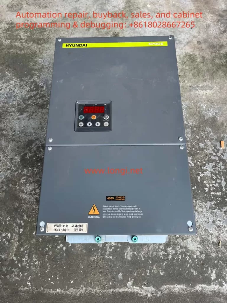
The operation panel of the Hyundai Inverter N700E Series is an important interface for user interaction with the inverter, mainly used for setting inverter parameters, monitoring operating status, and executing control commands. The operation panel is usually equipped with a display screen, which can display key parameters such as the operating frequency, current, and voltage of the inverter in real time; a run key for starting the inverter; a stop/reset key for stopping the inverter or resetting faults; and a frequency setting knob that allows users to manually adjust the output frequency of the inverter.
(II) Restoring Factory Default Settings
To restore the inverter parameters to factory settings, follow these steps:
- Enter the extended function mode (Group b parameters).
- Select the initialization mode (parameter b12).
- Set parameter b12 to “1”. The inverter will then clear the fault history and restore factory settings.
(III) Copying Parameters to Another Inverter
Although the manual does not directly mention the specific copying method, modern inverters generally support parameter copying through communication interfaces (such as RS485). The general steps are as follows:
- Connect the inverter to a computer using a dedicated communication cable.
- Use the software tool provided by the inverter manufacturer to upload the parameters of the source inverter to the computer.
- Download the saved parameters from the computer to the target inverter.
(IV) Setting Passwords and Access Restrictions
To protect the inverter settings from being changed arbitrarily, passwords and access restrictions can be set. For example, using the software lock function (parameter b09) can lock all parameters except the output frequency. Refer to the detailed steps in the manual for specific setting methods, which usually include entering the password setting mode, entering a new password, and selecting the parameters to be locked.
II. External Terminal Control and Speed Regulation Implementation
(I) Forward and Reverse Control via External Terminals
- Wiring Terminals: Use the FW (forward operation) and RV (reverse operation) terminals.
- Setting Parameters:
- Set parameter A02 (operation command selection) to “1” to select external terminal control mode.
- Ensure that parameter C01 (smart input terminal 1 setting) is set to “0” for forward operation and parameter C02 (smart input terminal 2 setting) is set to “1” for reverse operation.
- Control Circuit Wiring Diagram:
复制代码[FW] ----[Switch]----[CM1][RV] ----[Switch]----[CM1]When the switch between the [FW] terminal and the common terminal CM1 is closed, the inverter operates in the forward direction; when the switch between the [RV] terminal and the common terminal CM1 is closed, the inverter operates in the reverse direction.
(II) Speed Regulation via External Potentiometer
- Wiring Terminals: Connect an external potentiometer to the O (voltage input) and L (common) terminals.
- Setting Parameters:
- Set parameter A01 (frequency command selection) to “1” to select external voltage/current input mode.
- Ensure that the potentiometer is correctly connected to the O and L terminals. Rotate the potentiometer to adjust the output voltage and control the output frequency of the inverter.
- Control Circuit Wiring Diagram:
复制代码Potentiometer ----[O]----[Inverter] |\n [L]----[GND]
III. Inverter Fault Codes and Solutions
(I) Fault Codes and Their Meanings
| Fault Code | Fault Name | Meaning |
|---|---|---|
| E04 | Overcurrent Protection | Triggered when the inverter output current exceeds approximately 200% of the rated current |
| E05 | Overload Protection (Electronic Thermal Relay) | Triggered when the motor is overloaded |
| E07 | Overvoltage Protection | Triggered when the DC bus voltage exceeds the specified value |
| E09 | Undervoltage Protection | Triggered when the input voltage is below the specified value |
| E12 | External Fault | Triggered when the inverter receives a corresponding signal from an external device or unit that has malfunctioned |
| E13 | Unattended Start Error | Triggered when the inverter is already in operation upon power-on |
| E17 | Inverter Overload | Triggered when the power device IGBT overheats |
| E20 | Input Phase Loss | Triggered when an input AC power phase loss is detected |
| E21 | Temperature Trip | Triggered when the main circuit temperature rises due to the cooling fan stopping |
| E22 | Safety Function Fault | Triggered when the safety input signal is active |
(II) Fault Solutions
- E04/E17 (Overcurrent Protection/Inverter Overload):
- Check if the motor and load are too large, reduce the load or replace with a larger capacity inverter.
- Check for short circuits or ground faults in the motor windings.
- E05 (Overload Protection):
- Check if the motor is overloaded, reduce the load or adjust the protection level of the electronic thermal relay (through relevant parameter settings).
- Check the motor cooling condition and ensure good motor ventilation.
- E07/E09 (Overvoltage Protection/Undervoltage Protection):
- Check if the input power is stable and ensure the voltage is within the specified range.
- If the power is unstable, consider installing a voltage stabilizer.
- E12 (External Fault):
- Check external devices or units, troubleshoot and reset the inverter.
- E13 (Unattended Start Error):
- Ensure that the inverter is not in operation before powering on.
- E20 (Input Phase Loss):
- Check for input power phase loss and ensure normal three-phase power supply.
- E21 (Temperature Trip):
- Check if the cooling fan is working properly and ensure good heat dissipation of the inverter.
- Clean the dust and debris inside the inverter to improve heat dissipation conditions.
- E22 (Safety Function Fault):
- Check the safety input signal circuit and ensure normal safety function.
For all fault codes, first check the error code on the inverter’s display screen or operation panel, and then troubleshoot and resolve them step by step according to the fault troubleshooting procedures in the manual. If the problem persists, contact professional maintenance personnel or the technical support department of the inverter manufacturer in a timely manner to avoid more serious consequences.