
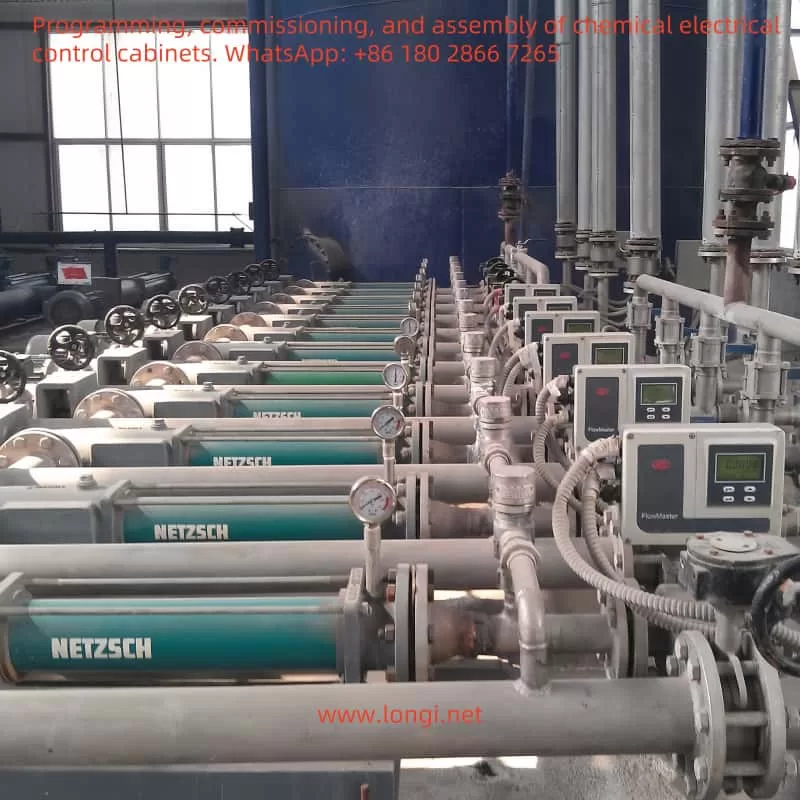
I. Application Scenario and Function Analysis
The main functions of chemical metering pumps include:
- Precise Flow Control: Achieve quantitative delivery of chemicals by adjusting the pump’s rotational speed.
- Start/Stop Control: Ensure smooth start and stop of the pump to avoid pressure surges.
- Pressure/Flow Feedback Regulation: Adjust the pump speed in real-time based on sensor feedback.
- Fault Protection: Automatic shutdown in case of overload, over-temperature, under-load, etc.
- Remote Monitoring and Operation: Realize automated operation through fieldbus or external controllers.
The VACON 100 HVAC inverter is suitable for these requirements. It supports multiple control methods (digital input, analog input, fieldbus), has built-in HVAC application macros, fault diagnosis functions, and rich parameter settings, which can well meet the control requirements of chemical metering pumps.
Specific Functional Positions in the Application
- Main Drive Motor: Drives the metering pump and controls its rotational speed to regulate the flow rate.
- Auxiliary Motor (if any): Used for the cooling system or stirring device (depending on the process requirements).
The following design focuses on a single main drive motor. If an auxiliary motor is required, it can be expanded according to similar logic.
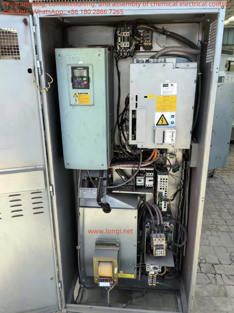
II. Hardware Selection
- Motor Selection
- Type: Three-phase asynchronous motor (commonly used in metering pumps). The power is selected according to the pump’s load requirements, such as 0.75 kW or 1.5 kW.
- Voltage: Match the inverter’s power supply voltage, such as 380 – 480 V (common industrial standard).
- Protection Level: The chemical environment may be corrosive, so it is recommended to choose a motor with an IP55 or higher protection level.
- Inverter Selection
- Model: VACON 100 HVAC. The rated current should be greater than the motor’s full-load current (e.g., for a 1.5 kW motor with a current of about 3.5 A, choose a model with a rated current ≥ 4 A).
- Power Supply: 380 – 480 V three-phase AC (refer to Section 7.1.2 of the installation manual).
- External Devices
- PLC: Select Siemens S7 – 1200 (such as 1214C) for logic control and data processing.
- Touch Screen: Siemens HMI TP700 Comfort for parameter setting and running status display.
- Sensors:
- Flow Sensor: Outputs a 4 – 20 mA analog signal for flow feedback.
- Pressure Sensor: Outputs a 4 – 20 mA analog signal for pressure monitoring.
- Relay: 24 V DC for controlling the start/stop signals.
III. Wiring Scheme
Refer to Section 7.2.1 of the installation manual and relevant sections of the application manual for information on the control terminals of the VACON 100 HVAC inverter. The following is the wiring design for the chemical metering pump:
- Power and Motor Wiring
- Power Input: Connect to the L1, L2, L3 terminals of the inverter (three-phase 380 V).
- Motor Output: Connect to the U, V, W terminals of the inverter and then to the three-phase motor.
- Grounding: Connect the PE terminal of the inverter to the grounding terminal of the motor to ensure grounding complies with the EN61800 – 5 – 1 standard (refer to Section 1.3 of the installation manual).
- Control Terminal Wiring
Refer to the technical information of the standard I/O board in Section 7.2.1 of the installation manual:
| Terminal | Function | Wiring Description |
|---|---|---|
| 1 | +10V Reference Voltage | Not used |
| 2 | AI1+ (Analog Input 1) | Connect to the flow sensor (positive pole of 4 – 20 mA output) |
| 3 | AI1- (Analog Input 1 Ground) | Connect to the flow sensor (negative pole of 4 – 20 mA output) |
| 4 | AI2+ (Analog Input 2) | Connect to the pressure sensor (positive pole of 4 – 20 mA output) |
| 5 | AI2- (Analog Input 2 Ground) | Connect to the pressure sensor (negative pole of 4 – 20 mA output) |
| 6 | 24V Auxiliary Voltage | Supply power to relays or sensors (if needed) |
| 7 | GND | Control signal ground |
| 8 | DI1 (Digital Input 1) | Connect to the PLC output (start signal) |
| 9 | DI2 (Digital Input 2) | Connect to the PLC output (stop signal) |
| 10 | DI3 (Digital Input 3) | Connect to the external emergency stop button (normally closed contact) |
| 11 | CM (Common Terminal A) | Common ground for DI1 – DI3 |
| 12 | 24V Auxiliary Voltage | Not used |
| 13 | GND | Not used |
| 18 | AO1+ (Analog Output 1) | Connect to the PLC input (output frequency feedback, 0 – 10 V) |
| 19 | AO1- (Analog Output Ground) | Common ground for analog output |
| A | RS485 A | Connect to the RS485 A terminal of the PLC |
| B | RS485 B | Connect to the RS485 B terminal of the PLC |
Wiring Diagram (Text Description)
- Power Input:
- L1 —- [Inverter L1]
- L2 —- [Inverter L2]
- L3 —- [Inverter L3]
- Motor Output:
- [Inverter U] —- [Motor U]
- [Inverter V] —- [Motor V]
- [Inverter W] —- [Motor W]
- Grounding:
- [Inverter PE] —- [Motor PE] —- [Grounding Wire]
- Control Signals:
- [PLC DO1] —- [DI1] (Start)
- [PLC DO2] —- [DI2] (Stop)
- [Emergency Stop Button] —- [DI3]
- [Flow Sensor +] —- [AI1+]
- [Flow Sensor -] —- [AI1-]
- [Pressure Sensor +] —- [AI2+]
- [Pressure Sensor -] —- [AI2-]
- [AO1+] —- [PLC AI1] (Frequency Feedback)
- [AO1-] —- [GND]
- [A] —- [PLC RS485 A]
- [B] —- [PLC RS485 B]
IV. Parameter Setting
The following parameter settings are based on the application manual and the requirements of the chemical metering pump. Use the start-up wizard and HVAC application macro of the VACON 100 for configuration.
- Start-up Wizard Settings (Refer to Page 4 of the Application Manual)
- Language: Select Chinese.
- Time: Set the current time (e.g., 14:30:00).
- Date: Set the current date (e.g., 15.10.2023).
- Application Macro: Select the HVAC application macro.
- Key Parameter Settings
| Parameter Number | Parameter Name | Setting Value | Description |
|---|---|---|---|
| P1.1 | Minimum Frequency | 10 Hz | Ensure the minimum running speed of the pump |
| P1.2 | Maximum Frequency | 50 Hz | Match the rated frequency of the motor (typical value) |
| P3.1.1 | Motor Rated Voltage | 380 V | Set according to the motor nameplate |
| P3.1.2 | Motor Rated Current | 3.5 A | Set according to the motor nameplate |
| P3.3.1 | Control Mode | 1 (Frequency Control) | Use frequency control mode |
| P3.5.1.1 | DI1 Function | 1 (Start) | DI1 controls start |
| P3.5.1.2 | DI2 Function | 2 (Stop) | DI2 controls stop |
| P3.5.1.3 | DI3 Function | 6 (External Fault) | DI3 is used for emergency stop |
| P3.6.1 | AI1 Signal Range | 1 (4 – 20 mA) | Flow sensor input |
| P3.6.2 | AI2 Signal Range | 1 (4 – 20 mA) | Pressure sensor input |
| P3.7.1 | AO1 Function | 1 (Output Frequency) | Output frequency feedback to the PLC |
| P3.14.1 | Overcurrent Protection | Enabled | Protect the motor and pump |
| P3.14.2 | Overload Protection | Enabled | Prevent motor overload |
- PID Control Settings (Flow Regulation)
- P3.9.1: Enable PID Control = 1
- P3.9.2: Setpoint Source = 0 (Fixed value, input from the touch screen)
- P3.9.3: Feedback Value Source = AI1 (Flow Sensor)
- P3.9.4: Proportional Gain = 2.0 (Adjust according to actual debugging)
- P3.9.5: Integral Time = 1.0 s (Adjust according to actual debugging)
V. Control System Design
- System Architecture
- PLC: Responsible for logic control, sensor signal processing, and communication with the inverter.
- Touch Screen: Display running status (rotational speed, flow rate, pressure) and set the target flow rate.
- Inverter: Execute motor rotational speed control, receive PLC instructions, and sensor feedback.
- Sensors: Provide real-time flow rate and pressure data.
- Control Logic
- Start/Stop:
- The PLC controls the inverter’s start/stop through DI1/DI2.
- The emergency stop button triggers DI3, and the inverter stops immediately.
- Flow Regulation:
- The touch screen inputs the target flow rate value, and the PLC transmits it to the inverter via RS485.
- The inverter adjusts the motor rotational speed through PID regulation based on the feedback from AI1 (flow sensor).
- Pressure Monitoring:
- AI2 (pressure sensor) monitors the pipeline pressure. If it exceeds the set range (e.g., > 5 bar), the PLC issues a stop command.
- Fault Handling:
- When the inverter detects a fault (e.g., overcurrent, fault code 1), it notifies the PLC via RS485, and the touch screen displays the fault information.
- Start/Stop:
Control Schematic Diagram (Text Description)
- [Touch Screen] —- [RS485] —- [PLC]
- | |
- | |—- [DO1] —- [DI1] (Start)
- | |—- [DO2] —- [DI2] (Stop)
- | |—- [AI1] —- [AO1] (Frequency Feedback)
- | |—- [RS485] —- [Inverter A/B]
- [Flow Sensor] —- [AI1+/-]
- [Pressure Sensor] —- [AI2+/-]
- [Emergency Stop Button] —- [DI3]
- [Inverter U/V/W] —- [Motor]
VI. Implementation Steps
- Installation and Wiring:
- Connect the power supply, motor, and control signals according to the wiring scheme.
- Ensure reliable grounding to avoid electromagnetic interference.
- Parameter Configuration:
- Initialize using the start-up wizard on the inverter panel.
- Input the above parameters and save the settings.
- PLC and Touch Screen Programming:
- Write the start/stop logic and PID control program for the PLC.
- Design the touch screen interface, including flow rate setting, running status, and fault alarms.
- Debugging:
- Manually test the start/stop functions.
- Adjust the PID parameters to ensure stable flow rate.
- Simulate faults to verify the protection functions.
- Operation and Optimization:
- After long-term operation, fine-tune the parameters according to the actual working conditions.
VII. Precautions
- Safety: Do not touch the internal circuits of the inverter after it is powered on (refer to Section 1.2 of the installation manual).
- EMC: The chemical environment may have interference, so adjust the EMC jumpers (refer to Section 6.3 of the installation manual).
- Support: If you encounter any problems, you can contact us.