
I. Introduction to Control Panel Functions
The control panel of the LS Servo APD-VS series is designed to be intuitive, comprising the following key components:
Operation Keys:
- Left/Right Keys: Used to switch between menu items for easy navigation.
- Up Key: Selects submenus or adjusts parameter values.
- Enter Key: Confirms selections or enters edit mode, executing commands such as tests or alarm resets.
Display Screen: Displays real-time system operating status, including key parameters such as current speed, position, torque, and load, facilitating user monitoring and diagnostics.
Menu Structure: - Status Menu (Pd-001 to Pd-020): Displays real-time data such as operating status, speed, torque, and load.
- Alarm Menu (PA-101 to PA-120): Records historical alarms for fault tracing.
- System Menu (PE-201 to PE-220): Configures system parameters, such as motor ID, encoder type, and communication speed.
- Control Menu (PE-301 to PE-320): Adjusts control parameters, such as inertia ratio, position/speed gain, and resonance suppression.
- Analog Menu (PE-401 to PE-420): Sets analog inputs/outputs, such as speed and torque commands.
- Input/Output Menu (PE-501 to PE-520): Manages I/O settings, including position error limits and brake control.
- Speed Operation Menu (PE-601 to PE-620): Configures speed-related operations and test runs.
- Pulse Operation Menu (PE-701 to PE-720): Handles position control settings, including pulse logic and electronic gear ratio.
- Command Menu (PC-801 to PC-820): Executes operations such as alarm reset, test run, and gain adjustment.
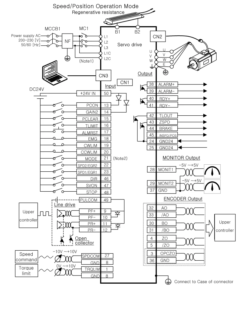
Connectors: - CN1 (Control Signal): Used to connect external control signals, supporting communication with a host computer or PLC.
- CN2 (Encoder): Connects to the encoder, providing motor position and speed feedback.
- CN3 (Communication): Supports RS232 or other communication protocols for interaction with a PC or host controller.
II. Setting Passwords and Access Restrictions
The LS Servo APD-VS series user manual does not explicitly mention a traditional password system but provides a “Menu Data Lock” function to restrict unauthorized parameter modifications:
Menu Data Lock Function:
- Enable or disable the lock function through menu [PC-810].
- In the locked state, attempting to modify menu data will display an “Err3” error, indicating that the menu is locked.
- Unlocking Operation: Return to [PC-810] and press the Enter key to switch to the “unLock” state, allowing parameter modifications.
III. Jog Operation
Jog operation (also known as manual test operation) is an important function for testing motor response or debugging. Below are the detailed steps:
Starting Jog:
- Enter command menu [PC-803] and press the Enter key to initiate the manual test.
- The system will cancel existing alarms, display the test operation speed, and start the motor.
Controlling Speed and Direction: - Use the Up key to switch between different test speeds set in [PE-602] to [PE-608].
- Press the Right key for forward rotation (counterclockwise) and the Left key for reverse rotation (clockwise).
Ending Operation: - Press the Enter key to stop the test and return to the menu.
IV. Position Mode and External Pulse Forward/Reverse Control
Position mode is suitable for applications requiring precise positioning, such as CNC machine tools or robotic arms. Below are the steps to configure external pulse forward/reverse control:
Setting Position Mode:
- Set the operation mode to “2” (position mode) in menu [PE-601].
Pulse Input: - External pulse signals are input through pins 9 (PF+), 10 (PF-), 11 (PR+), and 12 (PR-) of CN1.
- Two input methods are supported: line-driven 5V or open-drain 24V, to be selected based on the host controller.
Electronic Gear Ratio: - Use [PE-702] to [PE-709] to set the electronic gear ratio, defining the ratio between input pulses and encoder pulses.
Pulse Logic: - Set the pulse logic to N logic or P logic in [PE-701], determining the pulse direction interpretation for forward/reverse rotation.
V. Speed Mode and Forward/Reverse Control
Speed mode is used to control motor speed and is suitable for applications requiring stable speed. Below are the configuration steps:
Setting Speed Mode:
- Set the operation mode to “1” (speed mode) in menu [PE-601].
Speed Command: - Analog Command: Input through SPDCOM (pin 27), with a range of -10V to +10V, where positive and negative values correspond to forward and reverse directions, respectively.
- Digital Command: Select digital speed commands 1 to 7 through combinations of SPD1 (pin 23), SPD2 (pin 22), and SPD3 (pin 21).
Direction Control: - Use DIR (pin 46) and STOP (pin 48) inputs to control direction, configured through [PE-514].
VI. Fault Code Analysis and Solutions
The LS Servo APD-VS series provides a detailed list of fault codes to help users quickly diagnose and resolve issues. Below are common fault codes and their solutions:
| Fault Code | Meaning | Solution |
|---|---|---|
| Nor-off | Normal (servo off) | No action required |
| Nor-on | Normal (servo on) | No action required |
| L1.01 | RS232 communication error/control operation error | Replace the drive |
| AL-01 | Emergency stop | Check external DC24V power supply |
| AL-02 | Power failure | Check main power lines |
| AL-03 | Line fault | Check settings, CN2, U/V/W lines |
| AL-04 | Motor output fault | Check U/V/W lines and IPM module |
| AL-05 | Encoder pulse error | Check [PE-204] settings and CN2 lines |
| AL-06 | Following error | Check [PE-502] settings, lines, limit switches, gain |
| AL-08 | Overcurrent | Check output lines, motor/encoder settings, gain; replace the drive if necessary |
| AL-09 | Overload | Check load, brake operation, lines, motor/encoder settings |
| AL-10 | Overvoltage | Check input voltage, brake resistor, regenerative operation |
| AL-11 | Overspeed | Check encoder settings, lines, gain |
| AL-14~17 | Absolute encoder error | Check initial reset [PC-811], battery, encoder lines |
| AL-20~22 | Flash/initialization error | Replace the drive |
| AL-23 | Hardware error | Check [PE-203] settings |
| Err1 | Parameter modification during servo on | Adjust parameters after turning off the servo |
| Err2 | Data out of range | Input values within the valid range |
| Err3 | Menu locked | Unlock through [PC-810] |
General Solutions:
- Use [PC-801] or ALMRST (pin 17) to reset alarms.
- View alarm history [PA-101] to [PA-120] and use [PC-802] to clear history records to track new faults.
- Ensure all lines are connected correctly and parameters are set reasonably. If the problem persists, contact technical support.
Through this operation guide, users can better understand and use the LS Servo APD-VS series drive to ensure efficient and stable system operation.