
I. Background and Importance
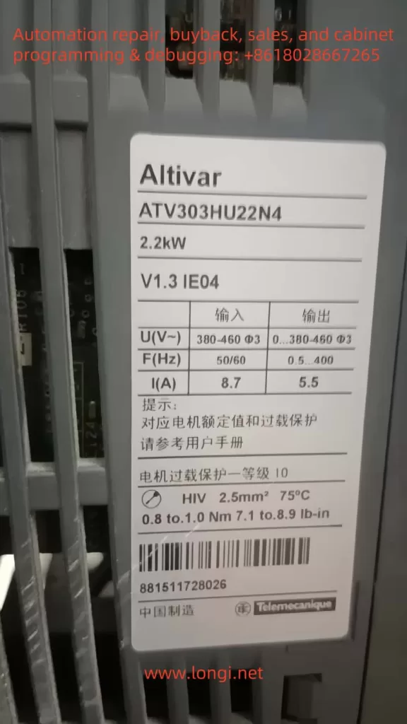
Within the realm of industrial automation, frequency inverters have become indispensable for motor control. Schneider Electric’s ATV series inverters enjoy a strong reputation for reliability and versatility, making them popular in many factories and engineering projects. The ATV303, in particular, is a cost-effective model frequently used with fans, pumps, and conveyor systems. For maintenance personnel, a solid understanding of the inverter’s fault and status codes is crucial for improving production efficiency, reducing downtime, and preventing unnecessary equipment damage.
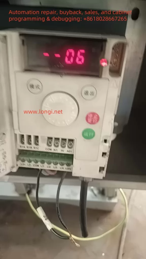
In actual usage, one may occasionally see the code “06” appear on the display panel of the ATV303 inverter. Since most real faults are labeled with an “F” prefix (e.g., F013 for motor overload or F011 for an overheat warning), many technicians might feel confused upon seeing “06”: Is it a fault code or just a normal state indicator? Is urgent shutdown and troubleshooting needed? In fact, the “06” code on the ATV303 is not a fault, but rather an indication of the Freewheel Stop state. This article provides a detailed explanation of the meaning of the “06” code, why it might appear, and how to deal with it properly so that readers can swiftly diagnose and address the situation.
II. The Real Meaning of Code 06
According to the official Schneider documentation for the ATV303, any code beginning with an “F” denotes an actual fault alarm—examples include F002, F006, F013, and so on. These alarms necessitate analysis of potential hardware or configuration issues, followed by the relevant reset or maintenance actions. In contrast, code “06” is explicitly categorized as a product status indicator. Rather than a hardware failure or system anomaly, it indicates a specific operational condition.
The “06” code stands for Freewheel Stop. In practical terms, freewheel stop means that the inverter is no longer supplying torque to the motor, allowing the motor shaft to come to rest solely through its own inertia. It differs from controlled or braked stopping methods: no active deceleration curve is applied, nor does the inverter inject direct current (DC) into the motor for braking. The time it takes the motor to stop primarily depends on load inertia.
Since the “06” state is not a failure, operators need not fear equipment damage or software errors. However, understanding why an inverter enters freewheel stop remains crucial. If “06” is triggered unexpectedly, it may disrupt normal operations or break the production rhythm. Only by identifying and addressing whatever caused the inverter to enter freewheel stop can the system resume normal operation.
III. Common Triggering Causes
- Activation of a Logic Input
The inverter’s logic inputs (e.g., LI1, LI2) can each be assigned custom functions. One of those functions is often “Freewheel Stop.” If a digital input is configured this way and happens to be energized—for instance, an external emergency stop circuit or sensor being triggered—then the ATV303 will automatically switch to freewheel stop and display “06.” - Selected Control Method
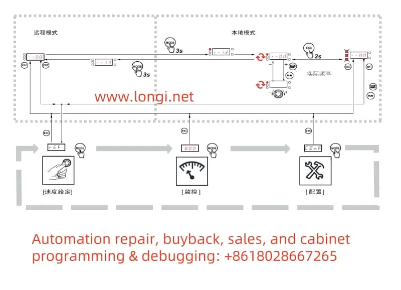
In two-wire control setups (i.e., one input for Run/Stop), the inverter waits for a valid Run signal after power-up. If that signal is absent or the wiring logic dictates a stop condition, the inverter might remain in freewheel stop. In some designs, the user must explicitly toggle the Run input once the inverter is powered up before it can exit “06.” - Local/Remote Switching
When the inverter is in remote-control mode, pressing the local STOP button or encountering a communication loss may force the inverter into freewheel stop. In these scenarios, code “06” will remain until a valid remote Run command is received again or communication is restored. - PID or Other Functional Settings
If the inverter is configured for closed-loop PID control and the feedback signal is lost—or the user deliberately set a “freewheel stop on signal loss” strategy—the inverter will carry out that plan by showing “06.” Once the signal is restored or a different stopping approach is chosen, the operator must send a new Run command to exit freewheel stop.
IV. Handling Approach and Detailed Operation
- Check the Logic Input Configuration
If you suspect a particular digital input is assigned to freewheel stop, inspect the assignment in the inverter’s configuration menu (COnF). Should you find that an input is set for FSt (Freewheel Stop) and it is in an active state (e.g., turned on), you can disable this input or remove its power signal to release the inverter from freewheel stop, returning it to a ready state. - Examine Emergency Stop or Safety Circuits
In many systems, an emergency stop circuit signals the inverter via a digital input or relay contact for freewheel stop. If an emergency stop is pressed, “06” will appear until you physically reset that emergency circuit. Ensure that no unsafe conditions remain in the machinery before re-engaging the e-stop circuit and clearing the “06” state. - Resend Run Command in a Two-Wire Control Setup
In a two-wire control scheme, you often need to remove and then reapply the Run signal after power-up. Without this, the inverter stays in freewheel stop mode. Once you provide the correct Run input, the inverter leaves “06” and begins outputting to the motor. - Use a Start Button in a Three-Wire Setup
If the system is wired for three-wire control (separate Start and Stop buttons), the inverter expects a start pulse after the stop button is released. Simply pressing the start button again should cause the display to switch from “06” to normal operation. - Check Communication Settings
In scenarios where the inverter is governed by serial communication from a PLC or computer, the absence of a valid run command or a temporary communication fault can lead to freewheel stop. Verify that the communication settings (baud rate, parity, data bits) match, and confirm the controller has issued the correct commands to restore normal drive operation. - Avoid Signal Loss
For advanced setups where the inverter is configured to freewheel stop upon losing an analog input (e.g., 4–20 mA), make sure sensors and cables are secure. Restoring the signal or adjusting the signal-loss strategy can eliminate “06.” Then, simply sending a valid run command should re-energize the motor.
V. Distinctions from Real Faults and Prevention
Unlike a code starting with “F,” which denotes actual faults requiring reset or more in-depth troubleshooting, “06” merely reflects the inverter’s execution of a normal freewheel stopping command. The user does not need to perform hardware inspections or a dedicated fault reset. However, an unintended or extended freewheel stop could disrupt production. Hence, it is crucial to configure your control logic carefully and secure all wiring to avoid unplanned “06” occurrences. Where higher safety requirements exist, you may prefer an alternative form of stopping such as fast ramp stop or DC injection, based on the demands of your process.
VI. Conclusion
To summarize, code “06” on the Schneider ATV303 inverter is not a sign of component malfunction. Instead, it indicates that the inverter is currently in Freewheel Stop mode—no torque or braking is being applied to the motor, so the load is free to coast to a standstill under its own inertia. Restoring normal operation involves determining the specific reason for freewheel stop—whether it’s a digital input function, an emergency stop condition, a missing run command, or a lost feedback signal. Once you remove or correct that cause, the inverter will automatically revert to a ready state (–00) or re-engage in normal operation if a run command is still active.
For real-world projects, ensuring your ATV303 is configured correctly—and that all external wiring and control signals are stable—will go a long way toward preventing unwanted freewheel stops from interrupting production. By grasping the function and handling of the “06” status, maintenance personnel can promptly troubleshoot and restore equipment to service, minimizing downtime and optimizing operational safety.
By understanding the meaning and responses associated with “06,” operators and technicians can effectively manage a common inverter behavior without confusion. Adhering to official Schneider documentation and combining that guidance with the specific control requirements of your system will ensure that the freewheel stop state works for you, rather than against you, in all industrial automation scenarios.