
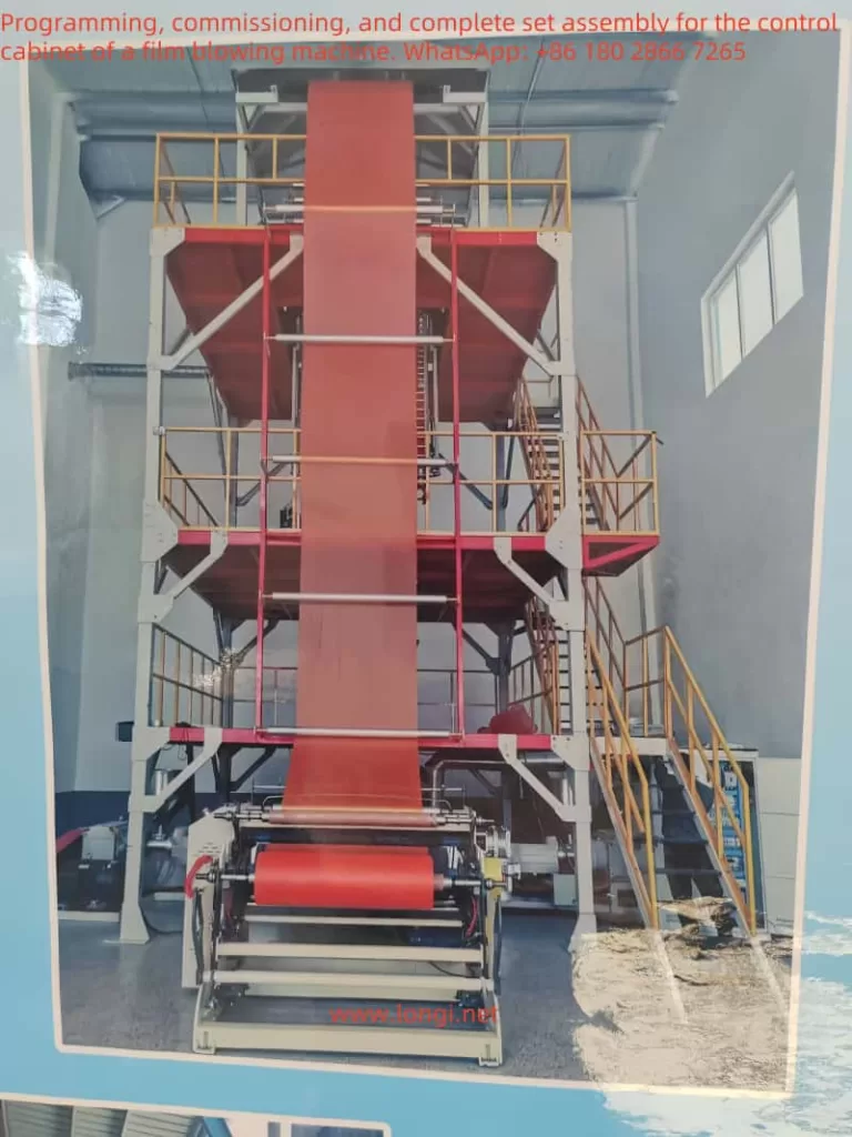
Below is a detailed application example based on the typical functional requirements of a film blowing machine, combined with the common wiring and parameter settings of the Yuqiang YQ3000-G11 inverter. Since a film blowing machine usually involves multiple drive lines (e.g., the main extruder motor, traction motor, winder motor, blower, etc.), this focuses on the control concepts, wiring diagrams, and parameter settings of the major sections for reference and subsequent adjustments.
I. Main Transmission Sections of the Film Blowing Machine and the Application Approach of the Inverter
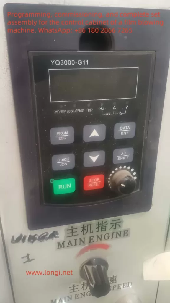
- Main (Extruder) Motor
- Function: Drives the screw to extrude the melt, controlling the basic output of the entire film blowing process.
- Inverter requirements: Generally requires higher power, smooth start, and stable torque output. Vector control or torque control mode can be used for better low-speed torque and speed stability.
- Key points: Usually requires an external speed reference (e.g., PLC/HMI for production or speed settings) or manual potentiometer for speed command.
- Traction Motor (sometimes called the stretching motor)
- Function: Continuously pulls the film upward from the die head, determining the stretching ratio and helping ensure uniform thickness.
- Inverter requirements: Medium power, accurate speed control, sometimes requiring multi-speed or tension control.
- Key points: Needs to coordinate with the main extruder speed, maintaining a stable line speed. Usually has a speed ratio with the main extruder or uses a tension sensor/dancing roller position sensor for closed-loop control.
- Winding Motor
- Function: Winds the formed film into rolls, potentially requiring constant tension or taper tension control.
- Inverter requirements: Must maintain stable tension even under a wide speed range. Sometimes paired with sensors or a tension controller.
- Key points: Depending on production line requirements, may adopt vector control with torque limit or rely on an external tension controller for speed regulation.
- Fan/Cooling Motor (e.g., air ring, cooling blower, etc.)
- Function: Provides stable cooling airflow for the film blowing process.
- Inverter requirements: Relatively medium or smaller power, typically just needs constant speed or simple speed control.
- Key points: Often uses multi-speed or simple inverter-based speed variation to adjust airflow volume.
II. Recommended Main Hardware and Control System
- Inverter
- Model: Yuqiang YQ3000-G11 (select power ratings according to each motor, such as 7.5kW, 11kW, 15kW, 22kW, etc.).
- Quantity: Depends on the number of motors that need control—commonly at least one each for the extruder, traction, and winding motors.
- PLC and HMI (Touch Screen)
- Suggest using a small PLC (e.g., Siemens S7-1200, Mitsubishi FX5U, or domestic brands like Xinje, Delta, etc.), plus a 7”–10” touch screen.
- Purpose: Centralized management of line speed reference, process parameters, tension or speed ratio control. The touch screen is used for operator interface, convenient speed adjustments, alarm displays, etc.
- Auxiliary Components
- Potentiometer (if only manual speed control is needed and not controlled by a PLC).
- Limit switches/proximity switches (to detect traction/tension roller positions).
- Tension sensor/dancing roller position sensor (if tension control is required).
- Common protection components such as contactors, circuit breakers, and thermal relays.
- If an encoder is needed (closed-loop vector or synchronization), choose an inverter model with encoder interface and the corresponding encoder.
III. Major Inverter Wiring Examples
Below is a detailed explanation taking the “main extruder motor” as an example. The wiring logic for traction/winder motors is similar. For multiple inverters, each will have similar main circuit wiring but will differ in how the control terminals interface with the PLC’s I/O.
1. Main Circuit Wiring Diagram
3-phase AC power (R,S,T) -----
                      |----- [Circuit breaker] -----|
                      |                             |
                      |---- [AC contactor (optional)] --|---- L1, L2, L3 ---> Inverter(YQ3000-G11) input
                      |

                      |----> Inverter(YQ3000-G11) output U, V, W ---> Main motor U, V, W

                      [PE] --------------------------> Inverter PE ----> Motor chassis ground
Note:
- For larger motors, it is advisable to add a contactor or soft starter on the input side of the inverter for protection or maintenance.
- Do not place contactors or switches between the inverter output and the motor, as this could lead to overcurrent or inverter damage.
- Proper grounding is mandatory for safety and to reduce electromagnetic interference.
2. Control Circuit (Low-Voltage Signals) Wiring Example
Below is a scenario where the PLC provides the run command and analog speed reference. If only one inverter is needed and you want manual speed control, you can connect a potentiometer to the AI terminal.
  PLC digital output Y0  ----------------> Inverter DI1 (Forward run)
  PLC digital output Y1  ----------------> Inverter DI2 (Reverse / other user-defined function)
  PLC digital output Y2  ----------------> Inverter DI3 (multi-step speed1 / e-stop reset / etc.)
  ...

  PLC common COM       ------------------> Inverter DCM (digital common)

  PLC analog output AO0(0-10V)  -------> Inverter AI1 (analog speed reference)
  PLC analog ground AGND         -----> Inverter GND (analog reference ground)

  Inverter relay output(FA/FB/FC) -----> PLC digital input X0/X1 (for fault alarm/running signal)
  Inverter DO(OC/OD) -------------> PLC digital input X2 (additional programmable output if needed)
Note:
- Typical naming for digital inputs is DI1, DI2, DI3…, with DCM as the common terminal; AIx are analog inputs, and GND is for analog reference; FA/FB/FC are relay outputs; OC/OD are open-collector outputs.
- You can assign various functions (e.g. multi-step speeds, jog mode, fault reset, emergency stop, etc.) to the DI terminals according to production line demands.
- If not using a PLC, a simple method is to set the inverter’s run command source to “panel/terminal” on the unit and connect a potentiometer (10kΩ–20kΩ) to AI1 to provide a manual speed reference.
IV. Key Function Parameter Settings
Below are typical function parameters of Yuqiang YQ3000-G11 inverters. Refer to the official manual for accuracy, as parameter numbers and names may vary by version. Common key parameters include:
- Control Method Selection
- For example:
P00.0 = 2means vector control (without PG);P00.0 = 0means V/F control. Choose based on motor characteristics and load requirements. - For closed-loop vector (with encoder), select a model supporting a PG card and set
P00.0to the corresponding mode (e.g., 3 or 4).
- For example:
- Run Command Source
- For example:
P00.1 = 1for terminal run commands;P00.1 = 2for communication (RS485/Modbus) run commands;P00.1 = 0for operation panel commands. - If the PLC’s digital outputs handle start/stop, set it to “terminal run command.”
- For example:
- Frequency Reference Source
- For example:
P00.2 = 1for AI1 analog input;P00.2 = 2for multi-step speed;P00.2 = 3for communication reference;P00.2 = 0for operation panel reference. - If the PLC’s analog output (0–10V) is used for speed reference, choose AI1.
- For example:
- Motor Parameter Settings (very important)
- Set motor rated power, current, voltage, frequency, and speed. For vector control, these must be accurate.
- E.g.,
P01.0~P01.4may correspond to rated voltage, rated current, rated power, rated frequency, rated speed (details depend on the manual).
- Acceleration/Deceleration Times
- For example:
P00.3(accel time),P00.4(decel time). Adjust based on process needs. For large-inertia extruders, slightly lengthen accel/decel to prevent shock.
- For example:
- Maximum Frequency / Base Frequency
- For example:
P00.5(max frequency),P00.6(upper frequency limit),P00.7(base frequency). Typically set to 50Hz or 60Hz, but can be increased if needed for the process.
- For example:
- Multi-Step Speeds / Simple Tension Control
- If multi-step speeds are required, configure the corresponding parameters (e.g.,
P10.x~P11.x) and digital terminals. - For constant tension control, use vector mode with torque limiting or external PID (internal to the inverter or from the PLC).
- If multi-step speeds are required, configure the corresponding parameters (e.g.,
- Fault Protection and Monitoring
- Set protection parameters such as overcurrent, overload, overvoltage, and choose how to reset faults (automatic or via terminal).
- Configure the inverter’s relay outputs for fault or running signals to feed back to the PLC.
V. Example of Specific Functional Implementation
- Extruder Motor Speed Control
- Hardware Link: PLC HMI -> PLC AO -> AI1 (inverter) -> inverter output -> motor
- Process:
- Operator sets the desired extruder screw speed/throughput on the HMI (corresponding to 0–10V or 4–20mA). The PLC sends this analog signal to AI1 on the inverter.
- The PLC also outputs a digital run command (RUN) to DI1 on the inverter, starting it.
- The inverter, using vector or V/F control, drives the extruder motor at the specified speed.
- If a fault occurs, the inverter’s relay feedback signals the PLC, and the HMI displays an alarm.
- Traction Motor Constant Line Speed Control
- If precise tension control is not needed, maintain a fixed ratio between traction speed and main extruder speed. The PLC calculates a proportional command from the extruder speed/frequency and outputs it to the traction inverter.
- For tension or speed tracking, use a tension sensor/dancing roller with a PID loop:
- The sensor provides a 4–20mA feedback to the PLC analog input, where a PID algorithm is carried out.
- The PLC analog output then drives AI1 on the traction inverter.
- Tuning the PID parameters keeps tension or roller position stable.
- Winding Motor Tension Control (Optional)
- A simple method is taper tension control, where torque or speed decreases as the roll diameter increases. Alternatively, use an external tension controller with the inverter.
- If the inverter has a built-in PID, the tension sensor signal can be fed into AI2, and the inverter automatically adjusts the output frequency to maintain tension. Or the PLC can handle the loop and send a command to the inverter.
- It is essential to coordinate with the traction speed to prevent slack or overstretching.
VI. Text-Based Wiring and Control Diagram (Simplified Example)
Below is a rough diagram using dashes, omitting some components and multiple motors. It highlights the main structure:
================= Three-Phase Power =================
|        R          S          T                    |
|        |          |          |                    |
|      [Breaker]  [Contactor]  ...                  |
|        |          |                               |
|        \-------- Inverter (L1,L2,L3) -------------/
|                 |
|                 |--- U --- Main motor U
|                 |--- V --- Main motor V
|                 \---W --- Main motor W
|
|---- [PE] ------ Inverter PE --- Motor chassis ground
|
|============= PLC (Digital/Analog IO) & HMI ============
       |         PLC: Y0 --------------> DI1 (Inverter)
       |         PLC: Y1 --------------> DI2 (Inverter)
       |         PLC: COM -------------> DCM (Inverter)
       |
       |         PLC: AO0(0-10V) ------> AI1 (Inverter)
       |         PLC: AGND -----------> GND (Inverter)
       |
       |<< Inverter FA/FB/FC (Fault/Run) >> PLC X0 etc.
       |
       |----- HMI (Comm port) <----> PLC (Comm port)
       |
=========================================================
To control traction, winding, and fan motors with separate inverters, replicate the main circuit connection (each with its own three-phase power supply and protective devices). The control circuit can be expanded by assigning more digital outputs and analog outputs in the PLC, or using RS485 communication to reduce the number of analog channels.
VII. Usage and Commissioning Recommendations
- Pre-Startup Check
- Verify the power supply voltage, wiring terminals, and grounding are correct.
- Use a multimeter to check the voltage/resistance of AI1, DI1, etc., to ensure they match the design.
- Ensure motor parameters are correctly set in the inverter.
- Initial No-Load Test Run
- Disconnect the motor from the load or run at low speed with no load. Observe current and voltage, and confirm correct rotation direction.
- Test emergency stop, fault protection, and reset functions.
- Load Test Run
- Gradually apply load from a low speed, watching for overcurrent or temperature issues.
- Observe the process effect (e.g., film thickness uniformity, tension stability) and adjust acceleration/deceleration time or PID parameters if necessary.
- Parameter Optimization
- If speed instability or tension fluctuation occurs, refine vector control gains, torque compensation, or PID settings as recommended by the manual.
- Optimize the PLC program for traction and winding speed/tension coordination.
- Fault and Protection
- Set appropriate fault levels (whether the drive stops immediately on alarm, etc.) and any delay features to avoid inadvertent stoppage or delayed protection.
- Regularly check the cooling path, filter, and fans for proper operation.
VIII. Conclusion
By using multiple Yuqiang YQ3000-G11 inverters, one can separately drive the main extruder, traction, and winding motors of a film blowing machine, thus realizing automated control over production rate (speed), film thickness (speed ratio), and tension (winding).
For wiring, the main circuit employs a three-phase input and U/V/W outputs to the motor. The control circuit can flexibly employ PLC/HMI digital and analog signals for start/stop and speed references.
When configuring parameters, accurately input the motor’s rated data and set reasonable acceleration/deceleration times, maximum frequency, torque boost, tension control, and multi-step speeds.
In more complex setups involving tension control, dancing roller control, or multi-segment process curves, further development can be done using the inverter’s built-in functions or PLC logic for greater flexibility and parameter optimization.