In the field of modern power electronics, the inverter module, as the core component of frequency converters, has its stability and reliability directly related to the operational efficiency and safety of the entire system. The A316J, as a widely used drive IC for inverter modules, occupies an important position in numerous frequency converter models due to its excellent performance. This article aims to deeply explore the characteristics of the A316J optocoupler drive, especially its fault detection and protection mechanisms, and analyze how these features affect the health of IGBT modules, thereby providing valuable references for professionals in related fields.

I. Overview of the A316J Optocoupler Drive
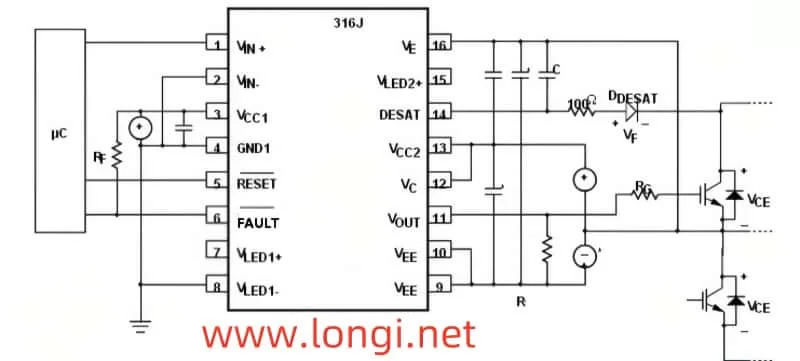
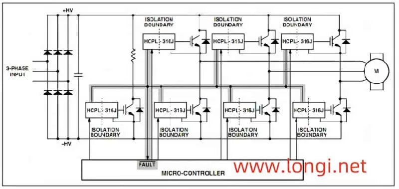
The A316J serves as a crucial drive component for inverter modules, primarily functioning to receive drive pulse signals from the CPU and convert them into drive signals suitable for IGBT module operation. This drive IC forms a closed loop with the C (collector) and E (emitter) poles of the driven IGBT tube through its 14th and 16th pins’ peripheral circuits, enabling effective monitoring of the IGBT tube’s operating state. During normal operation, the IGBT tube has a low on-state resistance, with a voltage drop typically below 3V. However, when abnormal overcurrent conditions occur, the voltage drop across the IGBT tube rises sharply, potentially damaging the tube. At this point, the A316J plays a pivotal role by detecting changes in the voltage drop, promptly blocking the output pulse, and sending an OC (overcurrent) alarm signal to the CPU to protect the IGBT module from further damage.

II. Fault Detection and Protection Mechanism of the A316J
The fault detection and protection mechanism of the A316J is one of its core functions. This mechanism continuously monitors the operating state of the IGBT tube and immediately takes protective measures once abnormalities are detected. Specifically, the A316J can detect the following three fault conditions:
- Excessive Operating Current Due to Load Abnormalities: When the load abnormalities cause the operating current to exceed the rated current significantly (usually by more than three times), the voltage drop across the IGBT tube rises rapidly, exceeding the 7V threshold. At this point, the A316J immediately blocks the output pulse and sends an OC alarm signal to the CPU.
- Open-Circuit Damage to the IGBT Tube: If the IGBT tube experiences open-circuit damage, it will fail to operate normally, resulting in an abnormally high voltage drop. The A316J can also detect this abnormality and take corresponding protective measures.
- Poor Drive Circuit: A poor drive circuit may cause the IGBT tube to be under-excited. Even if the output current is relatively small, the tube is in a partially conducting and randomly switching-off state, and the voltage drop may still exceed the action threshold. In this case, the A316J will also send an OC signal for alarm.

III. Harm to IGBT Modules Caused by A316J Faults and Case Study
Faults in the A316J not only affect its normal operation but may also cause severe damage to IGBT modules. The following is a typical fault case analysis:
A small-power frequency converter experienced abnormal sounds and vibrations from the motor, accompanied by OC shutdown phenomena, when the frequency rose above 20Hz after replacing a damaged IGBT module. After inspection, the fault was found to be caused by the failure of filtering capacitors in the peripheral circuit of the A316J. The failure of these capacitors reduced the power supply’s load-carrying capacity, making it difficult for the IGBT tube to turn on properly during high-speed or loaded operation, resulting in a large on-state resistance, severe three-phase imbalance, and subsequent motor vibration and OC alarms.
IV. Preventive Measures and Maintenance Suggestions
Given the potential harm caused by A316J faults to IGBT modules, the following are some preventive measures and maintenance suggestions:
- Regularly Check Filtering Capacitors in the Drive Power Supply: Ensure that the capacitance meets the specified requirements to avoid reduced power supply load-carrying capacity due to capacitor failure.
- Enhance Cooling Measures: For models with longer usage times or limited spaces, special attention should be paid to cooling issues to prevent component damage due to excessive temperatures.
- Regular Maintenance and Inspection: Regularly maintain and inspect frequency converters to promptly identify and address potential faults, ensuring the stable operation of the system.
In summary, as a key component of the inverter module, the performance stability and reliability of the A316J optocoupler drive are crucial to the operation of IGBT modules and even the entire frequency converter. By deeply understanding the characteristics and protection mechanisms of the A316J and adopting effective preventive measures and maintenance suggestions, we can effectively reduce the occurrence of faults and improve the stability and safety of the system.
