ACS510 Variable Frequency Drive (VFD) User Guide
I. Operating Panel Usage
- Power On/Off
Before powering on, ensure all connections are correct and the surrounding environment meets safety standards.
Use the power switch on the operating panel to turn the power on or off. - Mode Switching
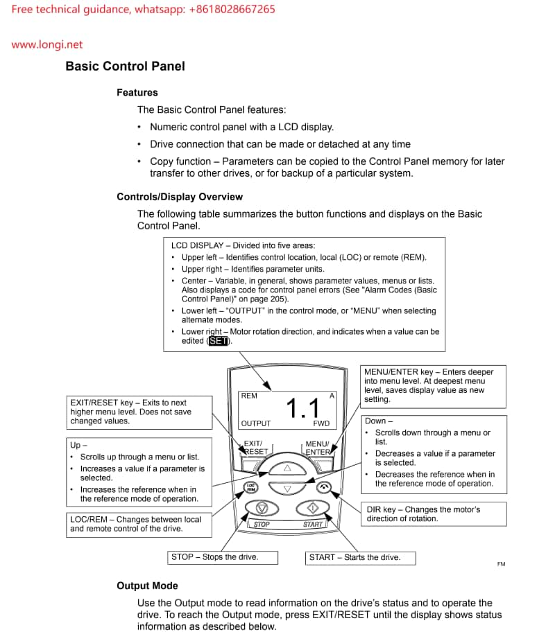
LOC/REM Button: Used to switch the control mode of the VFD. Press and hold this button for 2 seconds to toggle between Local Control (LOC) and Remote Control (REM) modes.
In Remote Control mode, the VFD can be controlled via external terminals or communication interfaces. - Display and Operation
Display: The LCD screen on the operating panel displays various status information of the VFD, such as motor speed, current, voltage, etc.
Button Operation: Use the Up/Down arrow buttons to navigate through menus and parameters. The MENU/ENTER button is used to enter and exit menus, while the EXIT/RESET button exits to the previous menu level or resets settings. - Parameter Modification
Enter the parameter mode, select the parameter group to be modified, adjust the parameter value using the Up/Down arrow buttons, and save the settings with the SAVE button.

II. VFD Terminal Start-up and Potentiometer Speed Control Wiring Methods
- Terminal Start-up Wiring
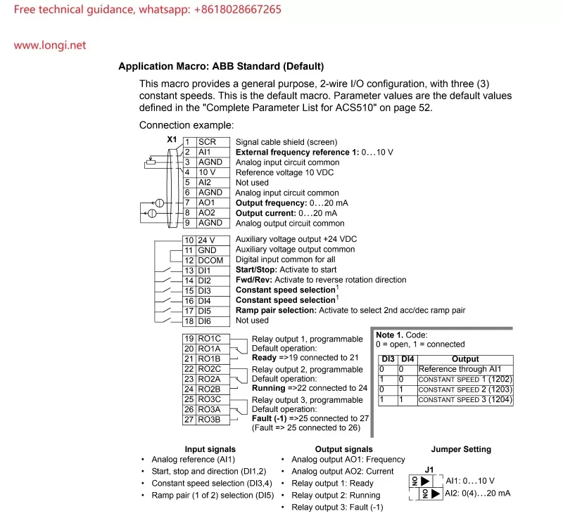
External Start Signal: Typically, connect the external start signal (e.g., a push-button switch) to the DI1 (Digital Input 1) terminal of the VFD and connect the common terminal to DI COM (Digital Input Common).
Direction Control: If direction control is required, connect the direction signal to the DI2 terminal.
Run Enable: Some applications may require an additional run enable signal, which can be connected to the appropriate DI terminal. - Potentiometer Speed Control Wiring
Analog Input Wiring: When using a potentiometer for speed control, connect the output terminal of the potentiometer to the AI1 (Analog Input 1) terminal of the VFD and connect AI COM (Analog Input Common) to the common terminal.
Parameter Setting: In parameter group 11, set Reference 1 Select (REF1 SELECT) to AI1 to ensure the VFD receives the speed reference signal from AI1.

III. Parameter Settings
- Selecting Standard Macros
Enter parameter group 99, find parameter 9902 (APPLIC MACRO), set it to 1, and select the ABB standard macro. This will automatically set a predefined set of parameters suitable for most general applications. - Motor Parameter Settings
Input the motor’s rated voltage (9905 MOTOR NOM VOLT), rated current (9906 MOTOR NOM CURR), rated frequency (9907 MOTOR NOM FREQ), rated speed (9908 MOTOR NOM SPEED), and rated power (9909 MOTOR NOM POWER), ensuring these parameters match the data on the motor’s nameplate. - Other Important Parameters
Acceleration Time (2202 ACCELER TIME 1): Sets the time required for the motor to accelerate from rest to maximum frequency.
Deceleration Time (2203 DECELER TIME 1): Sets the time required for the motor to decelerate from maximum frequency to rest.
Maximum Output Frequency (2008 MAXIMUM FREQ): Sets the maximum frequency output of the VFD.
IV. VFD Fault Code Analysis and Resolution Methods
- Overcurrent Fault (Code 1: OVERCURRENT)
Cause: Motor overload, excessively short acceleration time, motor fault, etc.
Solution: Check if the motor is overloaded, increase the acceleration time, inspect motor and cable connections. - DC Overvoltage (Code 2: DC OVERVOLT)
Cause: Excessively high input voltage, excessively short deceleration time, improper braking resistor, etc.
Solution: Check the input voltage, increase the deceleration time, inspect the braking resistor configuration. - Overtemperature Fault (Code 3: DEV OVERTEMP)
Cause: Excessively high ambient temperature, faulty cooling fan, dust accumulation, etc.
Solution: Lower the ambient temperature, clean dust, replace faulty fan. - Motor Stall (Code 12: MOTOR STALL)
Cause: Motor or load stall, improper motor selection, etc.
Solution: Inspect the motor and load, ensure correct motor selection. - Panel Loss (Code 10: PANEL LOSS)
Cause: Communication fault between the control panel and the VFD.
Solution: Check control panel connections, communication settings, and cables.
Please follow this guide for operation and adjust parameters and wiring according to actual conditions. If any issues arise, please contact us technical support promptly.
