
Application Scheme of Kinco CV20 Inverter in PE Pipe Packaging and Pipe Arranging Machine
I. Introduction
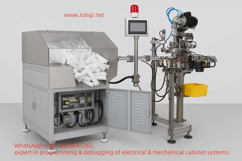
This document aims to design a detailed application scheme based on the Kinco CV20 inverter for the PE pipe packaging and pipe arranging machine (winding machine). The scheme covers motor function analysis, inverter selection, wiring methods, parameter settings, and control system integration. The pipe arranging machine uses a winding mechanism to evenly wrap PE pipes onto a reel, requiring precise control of winding speed and tension. The CV20 inverter, with its variable frequency speed regulation and communication capabilities, can meet the requirements of multi-motor coordinated control.
II. Motor Function Analysis for the Pipe Arranging Machine
Main Winding Motor
- Function: Drives the winding mechanism to control the winding speed and tension of the PE pipe.
- Parameters: Three-phase asynchronous motor, 380V/2.2kW.
Lateral Movement Motor
- Function: Drives the conduit device to move horizontally, ensuring even distribution of the pipes.
- Parameters: Three-phase motor (or single-phase), 380V/0.75kW.
Auxiliary Motor
- Function: Such as driving a conveyor belt, with low power and no need for inverter control.
- Application Positioning: The CV20 inverter is mainly used for speed regulation and synchronous control of the main winding motor and lateral movement motor.
III. CV20 Inverter Selection
| Motor Type | Model | Applicable Scenario |
|---|---|---|
| Main Winding Motor (2.2kW) | CV20-4T-0022G | Three-phase 380V input/output |
| Lateral Movement Motor (0.75kW) | CV20-4T-0007G | Three-phase 380V input/output |
| Lateral Movement Motor (Single-phase) | CV20-2S-0007G | Single-phase 220V input/output (optional) |
Key Features:
- Output Frequency: 0-300Hz, supports V/F control and automatic torque boost.
- Communication Interface: Built-in Modbus RS485, compatible with PLC integration.
- Environmental Adaptability: Temperature -10℃~50℃, humidity 5%~95%RH.
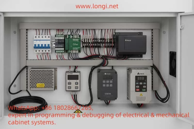
IV. Wiring Methods
1. Main Circuit Wiring
- Power Input: Three-phase 380V AC → Circuit Breaker → Inverter R/L1, S/L2, T/L3 (PE grounded).
- Motor Output: Inverter U/T1, V/T2, W/T3 → Motor U, V, W.
2. Control Circuit Wiring
- Control Methods:
- Keyboard Control: Directly set frequency and start/stop.
- Terminal Control:
- X1: Start/Stop
- X2: Forward/Reverse (Lateral Movement)
- X3: Emergency Stop
- AI1: Analog Frequency Input
- Communication Control: RS485 interface (+5V, 485+, 485-, GND) connected to PLC/HMI.
- Wiring Example:
复制代码Main Power (R,S,T,PE) ----> [Circuit Breaker] ----> [CV20-4T-0022G] (R/L1,S/L2,T/L3,PE) ----> [Main Winding Motor] (U,V,W) | |----> [CV20-4T-0007G] (R/L1,S/L2,T/L3,PE) ----> [Lateral Movement Motor] (U,V,W)Control Circuit:External Start Button ----> X1 (CV20-4T-0022G)Analog Signal Source ----> AI1 (CV20-4T-0022G)
V. Parameter Settings
1. Main Winding Motor (CV20-4T-0022G)
| Parameter | Setting Value | Description |
|---|---|---|
| P1 | 380V | Rated Voltage |
| P7 | 10s | Acceleration Time |
| P10 | Linear V/F | Constant Torque Load Mode |
| P41-P45 | Enable PID | Tension Control (requires sensor) |
2. Lateral Movement Motor (CV20-4T-0007G)
| Parameter | Setting Value | Description |
|---|---|---|
| P3 | 5Hz | Maximum Frequency (low-speed movement) |
| P20 | Triangle Wave Mode | Achieve reciprocating motion |
| P21 | Set according to winding width | Triangle wave period |
VI. PLC and HMI Selection
- PLC: Recommend Siemens S7-200 (e.g., S7-224) or Omron CP1E, supporting Modbus communication.
- HMI: Recommend Siemens KTP400 or Omron NB5W, for parameter setting and status monitoring.
- Communication Configuration:
- Inverter P51: Modbus-RTU protocol
- Baud Rate P52: 9600bps
- Control Architecture:
复制代码PLC ----> [RS485] ----> CV20-4T-0022G ----> Main Winding Motor | |----> [RS485] ----> CV20-4T-0007G ----> Lateral Movement Motor | |----> HMI (display status, set parameters)
VII. Function Realization
Main Winding Motor:
- Speed Control: Achieve multi-level winding speeds through frequency adjustment.
- Tension Control: PID closed-loop regulation (requires tension sensor).
Lateral Movement Motor:
- Reciprocating Motion: Automatic direction switching using triangle wave frequency mode.
- Synchronous Control: PLC reads the main motor frequency and dynamically adjusts the lateral speed.
VIII. Safety and Protection Measures
- Grounding Protection: PE terminal reliably grounded, grounding wire ≥3.5mm².
- Overcurrent Protection: Main circuit equipped with circuit breakers/fuses.
- Emergency Stop Function: X3 terminal connected to emergency stop button.
- Voltage Protection: Inverter built-in overvoltage/undervoltage alarm.
IX. Conclusion
The Kinco CV20 inverter can efficiently control the main winding and lateral movement motors of the PE pipe arranging machine through flexible wiring methods, parameter configuration, and communication functions. It is recommended to build an automated system in combination with PLC and HMI, with specific model selection referring to Siemens or Omron products. Users need to further optimize settings based on actual equipment parameters and follow the manufacturer’s safety specifications.
Note: This scheme is a general design, and parameters and wiring may need to be adjusted in actual applications based on equipment manuals and site conditions.