
Introduction
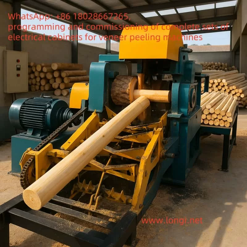
The rotary cutting machine is an essential piece of equipment in the woodworking industry, primarily used to peel logs into thin veneer sheets, which are widely applied in the production of plywood, furniture, and decorative materials. To achieve efficient and precise processing, the rotary cutting machine relies on the coordinated operation of multiple motors, including the main spindle motor for log rotation, the cutting blade motor for veneer cutting, the conveyor belt motor for veneer output, and the feed motor for controlling cutting thickness. These motors require precise speed and torque control to ensure processing quality and production efficiency. As a versatile electrical device capable of flexibly controlling motor operation, the inverter plays a critical role in the rotary cutting machine.
This article provides a detailed explanation of how to apply the Mobeck MT110 inverter to various motor control aspects of a rotary cutting machine, covering functional analysis, inverter selection, wiring design, parameter settings, and the integration of PLC and touchscreen systems. Through a well-designed and implemented solution, the rotary cutting machine can achieve efficient, stable, and automated operation, meeting the demands of modern woodworking processes.
Functional Analysis of the Rotary Cutting Machine
The primary task of a rotary cutting machine is to process logs into veneer sheets, involving log fixation and rotation, cutting by the blade, veneer output, and precise control of cutting thickness. Below is a detailed analysis of the main motor functions in a rotary cutting machine:
1. Main Spindle Motor (Rotation Function)
- Function: The main spindle motor drives the log to rotate, serving as the core power component of the rotary cutting machine.
- Characteristics: It requires high power, typically ranging from 5.5 kW to 15 kW (depending on the machine size), and needs stable speed output while allowing dynamic speed adjustments based on processing requirements.
- Control Requirements: The inverter must support vector control mode to ensure high torque output at low speeds and be capable of receiving external speed reference signals (e.g., from a PLC or potentiometer).
2. Cutting Blade Motor (Cutting Function)
- Function: This motor drives the cutting blade to peel the rotating log into veneer sheets.
- Characteristics: The power typically ranges from 3 kW to 7.5 kW, with speed adjustments required based on veneer thickness, and stable torque support during cutting.
- Control Requirements: The inverter needs fast start/stop capabilities and precise speed control, often requiring synchronization with the main spindle motor.
3. Conveyor Belt Motor (Conveying Function)
- Function: It ensures the smooth output of cut veneer sheets, maintaining production continuity.
- Characteristics: The power is relatively low, typically between 0.75 kW and 2.2 kW, with speed needing to match the cutting rhythm.
- Control Requirements: The inverter should support simple speed regulation and may need to operate in coordination with the cutting blade motor.
4. Feed Motor (Feed Function)
- Function: It controls the feed speed of the cutting blade or log, directly determining the veneer thickness.
- Characteristics: The power is low (0.75 kW to 1.5 kW), and it can be either an asynchronous motor or a servo motor, requiring high-precision speed control.
- Control Requirements: If using an asynchronous motor, the inverter must support high-precision speed regulation and accept external analog signal inputs; if using a servo motor, a dedicated servo drive is required.
5. Other Auxiliary Motors
- Function: These include motors for clamping devices, chip removal fans, etc., used to assist the processing operation.
- Characteristics: The power is low (0.37 kW to 1.5 kW), with simple control requirements, typically needing only basic start/stop functions.
From the above analysis, it is clear that the motor control requirements of a rotary cutting machine are diverse. The main spindle and cutting blade motors demand high-performance control, while the conveyor belt and feed motors prioritize speed stability and precision. The Mobeck MT110 inverter, with its flexible control modes and rich functionality, is an ideal choice to meet these requirements.
Application Scheme of Mobeck MT110 Inverter
1. Inverter Application Positions
Based on the functional characteristics of the rotary cutting machine, the Mobeck MT110 inverter can be applied to the following key motor positions:
- Main Spindle Motor: Use the MT110 inverter for vector control to ensure stable log rotation.
- Cutting Blade Motor: Use the MT110 inverter for speed control, synchronized with the main spindle motor.
- Conveyor Belt Motor: Use the MT110 inverter for simple speed regulation.
- Feed Motor: If an asynchronous motor is used, the MT110 inverter can provide high-precision speed control; if a servo motor is used, a separate servo drive is required.
2. Inverter Selection
Assuming a medium-sized rotary cutting machine with the following motor power configuration:
- Main Spindle Motor: 7.5 kW
- Cutting Blade Motor: 5.5 kW
- Conveyor Belt Motor: 1.5 kW
- Feed Motor: 1.1 kW (asynchronous motor)
Based on the motor power and load characteristics, the following Mobeck MT110 inverter models are selected:
- Main Spindle Motor: MT110-7.5kW (rated power 7.5 kW, 380V three-phase)
- Cutting Blade Motor: MT110-5.5kW (rated power 5.5 kW, 380V three-phase)
- Conveyor Belt Motor: MT110-1.5kW (rated power 1.5 kW, 380V three-phase)
- Feed Motor: MT110-1.1kW (rated power 1.1 kW, 380V three-phase)
When selecting the inverter, ensure that its rated capacity is slightly higher than the motor power to provide a margin for potential overload conditions.
3. Wiring Design
The following uses the main spindle motor (7.5 kW) MT110 inverter as an example to detail the wiring method. The wiring for other motors is similar, with adjustments based on power and control requirements.
(1) Main Circuit Wiring
- Power Input: Connect the three-phase 380V power supply to the inverter’s R, S, and T terminals.
- Motor Output: Connect the inverter’s U, V, and W terminals to the three-phase input of the main spindle motor.
- Grounding: Connect the inverter’s grounding terminal and the motor’s grounding terminal to the ground wire to ensure electrical safety.
Main Circuit Wiring Diagram (Text Description):
Power Supply (380V Three-Phase)
  L1 ---- R
  L2 ---- S
  L3 ---- T
         |
         |---- Ground Terminal ---- Ground
         |
  U ---- Motor U Phase
  V ---- Motor V Phase
  W ---- Motor W Phase
         |
         |---- Motor Ground Terminal ---- Ground
(2) Control Circuit Wiring
The control terminals of the MT110 inverter include digital inputs (DI), analog inputs (AI), and relay outputs (RO). Using the main spindle motor control as an example:
- Start/Stop Control:
- DI1 (Forward Start): Connect to the PLC output point (e.g., Y0) to control inverter start via the PLC.
- DI2 (Stop): Connect to the PLC output point (e.g., Y1) to control inverter stop via the PLC.
- COM: Common terminal, connected to the PLC’s common terminal.
- Speed Reference:
- AI1 (Analog Input): Connect to the PLC’s analog output module (0-10V signal) for speed regulation.
- GND: Analog ground, connected to the PLC’s analog ground.
- Fault Output:
- RO1A/RO1B (Relay Output): Connect to the PLC input point (e.g., X0) to detect inverter faults.
Control Circuit Wiring Diagram (Text Description):
PLC Output
  Y0 ---- DI1 (Forward Start)
  Y1 ---- DI2 (Stop)
  COM ---- PLC Common Terminal

PLC Analog Output
  0-10V ---- AI1 (Speed Reference)
  GND ---- GND

Inverter Relay Output
  RO1A ---- X0 (PLC Input, Fault Detection)
  RO1B ---- PLC Common Terminal
4. Parameter Settings
Using the main spindle motor (7.5 kW) MT110 inverter as an example, the key parameter settings are listed below. Assuming the MT110 inverter’s parameter numbering is similar to that of a general-purpose inverter, the settings are as follows:
- P0.03 (Control Mode): Set to 1 (Vector Control without PG), suitable for the high torque requirements of the main spindle motor.
- P0.04 (Run Command Source): Set to 1 (Terminal Control), using DI1/DI2 for start/stop control.
- P0.06 (Frequency Reference Source): Set to 2 (AI1 Analog Input), using the PLC’s 0-10V signal to set the speed.
- P1.00 (Motor Rated Power): Set to 7.5 (7.5 kW).
- P1.01 (Motor Rated Voltage): Set to 380 (380V).
- P1.02 (Motor Rated Frequency): Set to 50 (50 Hz).
- P1.03 (Motor Rated Speed): Set to 1460 (assuming a 4-pole motor, approximately 1460 rpm at 50 Hz).
- P2.00 (Acceleration Time): Set to 5 (5 seconds) to avoid startup shock.
- P2.01 (Deceleration Time): Set to 5 (5 seconds) to ensure smooth stopping.
- P5.00 (DI1 Function): Set to 1 (Forward Run).
- P5.01 (DI2 Function): Set to 2 (Stop).
- P6.00 (Relay Output Function): Set to 1 (Fault Output).
Parameter settings for other motors should be adjusted based on their specific functions:
- Cutting Blade Motor: Set acceleration/deceleration time to 3 seconds to accommodate fast start/stop requirements.
- Conveyor Belt Motor: Use V/F control (P0.03=0) to simplify control logic.
- Feed Motor: Requires high-precision speed control, so adjust the gain and offset parameters of AI1 (e.g., P4 group parameters).
Parameter Settings Example Table:
| Parameter No. | Description | Main Spindle Motor | Cutting Blade Motor | Conveyor Belt Motor | Feed Motor |
|---|---|---|---|---|---|
| P0.03 | Control Mode | 1 (Vector) | 1 (Vector) | 0 (V/F) | 1 (Vector) |
| P0.04 | Run Command Source | 1 (Terminal) | 1 (Terminal) | 1 (Terminal) | 1 (Terminal) |
| P0.06 | Frequency Reference Source | 2 (AI1) | 2 (AI1) | 2 (AI1) | 2 (AI1) |
| P1.00 | Motor Rated Power (kW) | 7.5 | 5.5 | 1.5 | 1.1 |
| P2.00 | Acceleration Time (s) | 5 | 3 | 2 | 2 |
| P2.01 | Deceleration Time (s) | 5 | 3 | 2 | 2 |
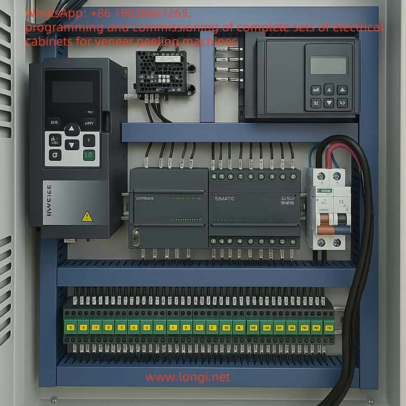
5. PLC and Touchscreen Selection and Application
(1) Selection
To achieve automated control of the rotary cutting machine, a PLC and touchscreen are required:
- PLC: Recommend the Siemens S7-200 SMART series (e.g., CPU 224XP), which supports analog input/output and offers strong scalability.
- Touchscreen: Recommend the Siemens KTP400 Basic (7-inch), which supports communication with the PLC via Profinet and provides an intuitive operation interface.
(2) PLC Program Design
The PLC is responsible for coordinating the operation of each motor, with the main functions including:
- Start/Stop Control: Use PLC output points (e.g., Y0, Y1) to control the DI1/DI2 of each inverter, enabling motor start/stop.
- Speed Regulation: Use the PLC’s analog output module (0-10V) to control the inverter’s AI1, dynamically adjusting each motor’s speed.
- Synchronization Control: Calculate the speed ratio between the main spindle motor and the cutting blade motor through the program to ensure consistent cutting thickness.
- Fault Detection: Use the inverter’s relay output (RO1A/RO1B) to send fault signals to the PLC input point (e.g., X0), triggering an alarm.
PLC Control Diagram (Text Description):
PLC
  Y0 ---- Main Spindle Inverter DI1 (Start)
  Y1 ---- Main Spindle Inverter DI2 (Stop)
  AO0 ---- Main Spindle Inverter AI1 (Speed Reference)
  X0 ---- Main Spindle Inverter RO1A (Fault Input)

  Y2 ---- Cutting Blade Inverter DI1 (Start)
  Y3 ---- Cutting Blade Inverter DI2 (Stop)
  AO1 ---- Cutting Blade Inverter AI1 (Speed Reference)
  X1 ---- Cutting Blade Inverter RO1A (Fault Input)

Touchscreen ---- PLC (via Profinet Communication)
PLC Program Pseudo-Code Example:
VAR
    Start_Main : BOOL;        // Main Spindle Motor Start Signal
    Stop_Main : BOOL;         // Main Spindle Motor Stop Signal
    Speed_Main : REAL;        // Main Spindle Motor Speed (0-10V)
    Start_Feed : BOOL;        // Feed Motor Start Signal
    Stop_Feed : BOOL;         // Feed Motor Stop Signal
    Speed_Feed : REAL;        // Feed Motor Speed (0-10V)
    Start_Conveyor : BOOL;    // Conveyor Belt Motor Start Signal
    Stop_Conveyor : BOOL;     // Conveyor Belt Motor Stop Signal
    Speed_Conveyor : REAL;    // Conveyor Belt Motor Speed (0-10V)
END_VAR

// Main Spindle Motor Control
IF Start_Main AND NOT Stop_Main THEN
    Inverter_Main.CommandWord := 16#83; // Run Forward
    Inverter_Main.FrequencyReference := Speed_Main * 5; // 0-10V corresponds to 0-50Hz
ELSE IF Stop_Main THEN
    Inverter_Main.CommandWord := 16#80; // Stop
END_IF

// Feed Motor Control
IF Main_Spindle_At_Speed AND Start_Feed AND NOT Stop_Feed THEN
    Inverter_Feed.CommandWord := 16#83;
    Inverter_Feed.FrequencyReference := Speed_Feed * 5;
ELSE IF Stop_Feed THEN
    Inverter_Feed.CommandWord := 16#80;
END_IF

// Conveyor Belt Motor Control
IF Cutting_In_Progress AND Start_Conveyor AND NOT Stop_Conveyor THEN
    Inverter_Conveyor.CommandWord := 16#83;
    Inverter_Conveyor.FrequencyReference := Speed_Conveyor * 5;
ELSE IF Stop_Conveyor THEN
    Inverter_Conveyor.CommandWord := 16#80;
END_IF
(3) Touchscreen Interface Design
The touchscreen is used for parameter settings and operation status monitoring, with the main interfaces including:
- Main Interface: Displays the operation status (running/stopped), current speed (Hz), and fault status of each motor.
- Parameter Setting Interface: Sets the target speed of each motor (via PLC AO output) and veneer thickness (via feed motor speed adjustment).
- Alarm Interface: Displays inverter fault information (e.g., overload, overheating) and provides a reset button.
6. Safety Considerations
To ensure the safe operation of the equipment, the following precautions should be observed:
- Electrical Safety: Ensure reliable grounding of the inverter and motor to prevent electrical leakage risks.
- Operational Safety: Set an emergency stop button on the touchscreen, allowing the PLC to stop all inverters simultaneously.
- Overload Protection: Enable overload protection in the inverter parameters (e.g., P9 group parameters) to prevent motor overheating.
- Maintenance Safety: Regularly inspect the inverter’s cooling fan and wiring terminals to ensure long-term operational stability.
Conclusion
Through the above scheme, the Mobeck MT110 inverter can fully meet the control requirements of a rotary cutting machine:
- Main Spindle Motor: Achieves smooth log rotation with adjustable speed, ensuring processing continuity.
- Cutting Blade Motor: Operates synchronously with the main spindle motor, ensuring cutting quality.
- Conveyor Belt Motor: Provides stable veneer output, with speed matching the cutting rhythm.
- Feed Motor: Precisely controls veneer thickness, improving product consistency.
- PLC and Touchscreen: Enable automated control and human-machine interaction, enhancing equipment efficiency and ease of operation.
The advantages of this scheme lie in its modular design and flexibility, allowing users to adjust motor power, inverter models, and control parameters based on actual needs. Additionally, the integration of a PLC and touchscreen enables the rotary cutting machine to achieve a higher level of automation, significantly improving production efficiency and product quality.