
I. Overview
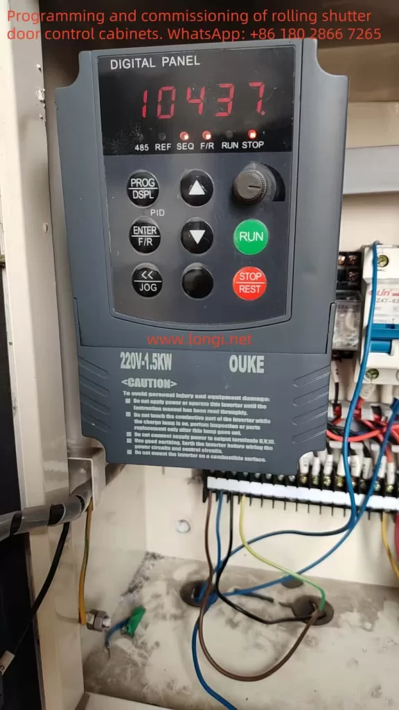
This scheme aims to apply the Ouke inverter GD320 to roller shutter equipment to achieve precise control of the motor. Combining the technical data of the Lingshida inverter and the application requirements of the roller shutter equipment, this scheme details the motor application positions, wiring methods, parameter settings, and PLC control schemes.
II. Motor Application Positions and Functions
In roller shutter equipment, motors are mainly used in the following positions and functions:
- Opening/Closing Function:
- The motor drives the lifting of the shutter to open and close it.
- Position: The motor is usually installed at one end of the shutter shaft and drives the shaft to rotate through a transmission device.
- Limit Function:
- The motor works with limit switches to ensure that the shutter stops accurately at predetermined positions when opening and closing.
- Position: Limit switches are installed at the top and bottom of the shutter track.
- Safety Protection Function:
- The motor cooperates with infrared protection devices. When an obstacle is detected, the motor stops or reverses to avoid crushing.
- Position: Infrared protection devices are installed on both sides or the bottom of the shutter.
- Emergency Stop Function:
- In an emergency, the motor power supply is cut off through an emergency stop button or password switch, causing the shutter to stop immediately.
- Position: Emergency stop buttons or password switches are installed in easily accessible positions.
III. Wiring Methods
- Main Circuit Wiring
- Power Wiring: Connect the three-phase power supply (L1, L2, L3) to the inverter’s RST terminals.
- Motor Wiring: Connect the motor’s UVW terminals to the inverter’s UVW terminals.
- Precautions:
- Ensure that the power supply and motor phase sequences are consistent to avoid motor reversal.
- Check if the wire ends are secure after wiring to avoid poor contact.
- Control Circuit Wiring
- Control Signal Wiring:
- Start/Stop Signal: Connect the start button and stop button to the inverter’s FWD and REV terminals, respectively.
- Speed Signal: If external speed adjustment is needed, connect a potentiometer or analog signal output from the PLC to the inverter’s AI terminal.
- Limit Switch Signal: Connect the upper and lower limit switches to the inverter’s LI1 and LI2 terminals, respectively.
- Precautions:
- The control circuit should use shielded wires to avoid electromagnetic interference.
- The control circuit and main circuit should be wired separately to ensure safety.
- Control Signal Wiring:
- Grounding Wiring
- Reliably ground the grounding terminals of the inverter and motor to ensure equipment safety.
IV. Parameter Settings
- Basic Parameter Settings
- Pr000: Password
- Set to
000to unlock parameters.
- Set to
- Pr001: Operating Frequency Setting
- Set to
50Hz(adjust according to the motor’s rated frequency).
- Set to
- Pr002: Operating Control Mode
- Set to
1(terminal command control).
- Set to
- Pr000: Password
- Motor Parameter Settings
- Pr003: Main Frequency Setting Method
- Set to
1(analog input).
- Set to
- Pr004: Base Frequency
- Set to
50Hz(consistent with the motor’s rated frequency).
- Set to
- Pr005: Maximum Output Voltage
- Set to
380V(adjust according to the motor’s rated voltage).
- Set to
- Pr003: Main Frequency Setting Method
- Acceleration/Deceleration Time Settings
- Pr006: Acceleration Time 1
- Set to
10s(adjust according to actual needs).
- Set to
- Pr007: Deceleration Time 1
- Set to
10s(adjust according to actual needs).
- Set to
- Pr006: Acceleration Time 1
- Limit Switch Settings
- Pr008: Upper Limit Frequency
- Set to
50Hz(consistent with the motor’s rated frequency).
- Set to
- Pr009: Lower Limit Frequency
- Set to
0Hz.
- Set to
- Pr010: Electronic Thermal Relay Action Selection
- Set to
1(electronic thermal relay action).
- Set to
- Pr008: Upper Limit Frequency
- PID Control Settings (if needed)
- Pr011: PID Setpoint
- Set according to actual needs.
- Pr012: PID Feedback Value
- Set according to actual needs.
- Pr013: PID Proportional Gain
- Adjust according to actual needs.
- Pr014: PID Integral Time
- Adjust according to actual needs.
- Pr015: PID Derivative Time
- Adjust according to actual needs.
- Pr011: PID Setpoint
V. PLC Control Scheme
- PLC Selection
- Choose a PLC with analog and digital outputs, such as Siemens S7-200 SMART.
- PLC and Inverter Wiring
- Analog Output: Connect the PLC’s analog output module to the inverter’s AI terminal to adjust motor speed.
- Digital Output: Connect the PLC’s digital output module to the inverter’s FWD, REV, LI1, LI2, and other terminals to control motor start, stop, and limits.
- PLC Programming
- Manual Control Program:
- Control motor start, stop, and forward/reverse rotation through buttons.
- Program example (ladder diagram):
复制代码| I0.0 (Start Button) |---|---|---| Q0.0 (Inverter FWD)| I0.1 (Stop Button) |---|---|---| Q0.1 (Inverter REV)
- Automatic Control Program:
- Detect obstacles through sensors or infrared protection devices and control motor stop or reverse.
- Program example (ladder diagram):
复制代码| I0.2 (Infrared Sensor) |---|---|---| Q0.2 (Inverter LI1)| I0.3 (Lower Limit Switch)|---|---|---| Q0.3 (Inverter LI2)
- Manual Control Program:
- Communication Settings (if needed)
- If more complex control functions are required, communication between the PLC and inverter can be achieved through the RS-485 interface.
- Set the inverter’s communication parameters, such as baud rate, data bits, stop bits, etc., to ensure consistency with the PLC.
VI. Conclusion
This scheme details the application of the Ouke inverter GD320 in roller shutter equipment, including motor application positions, wiring methods, parameter settings, and PLC control schemes. Through reasonable wiring and parameter settings, precise control of roller shutter equipment can be achieved, improving equipment stability and safety. If further customization or optimization of the scheme is needed, adjustments can be made based on actual equipment requirements.