Introduction
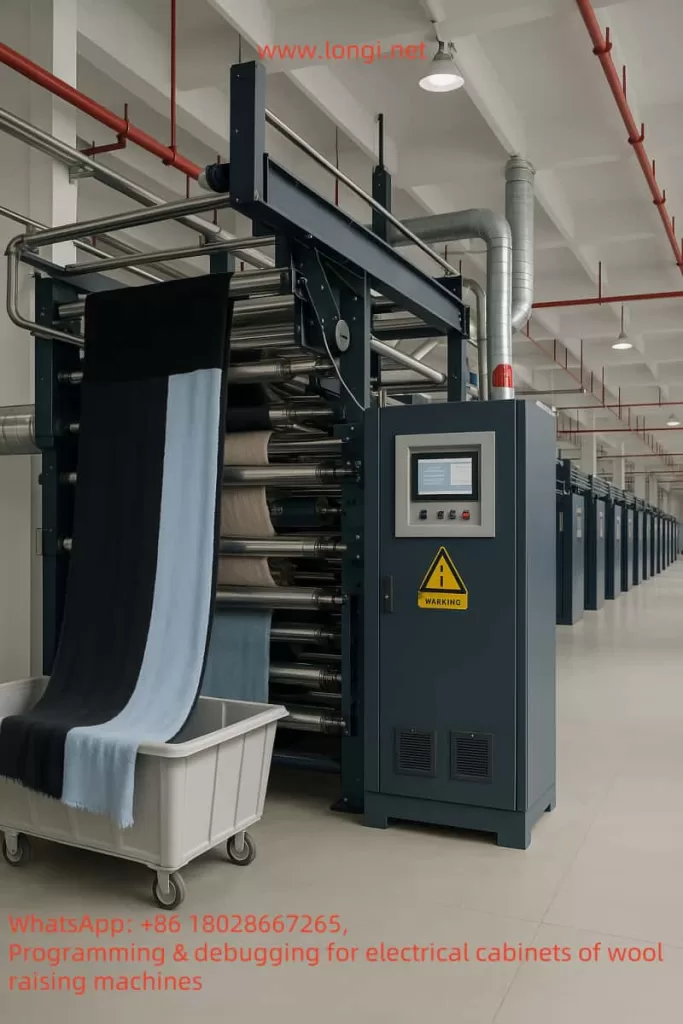
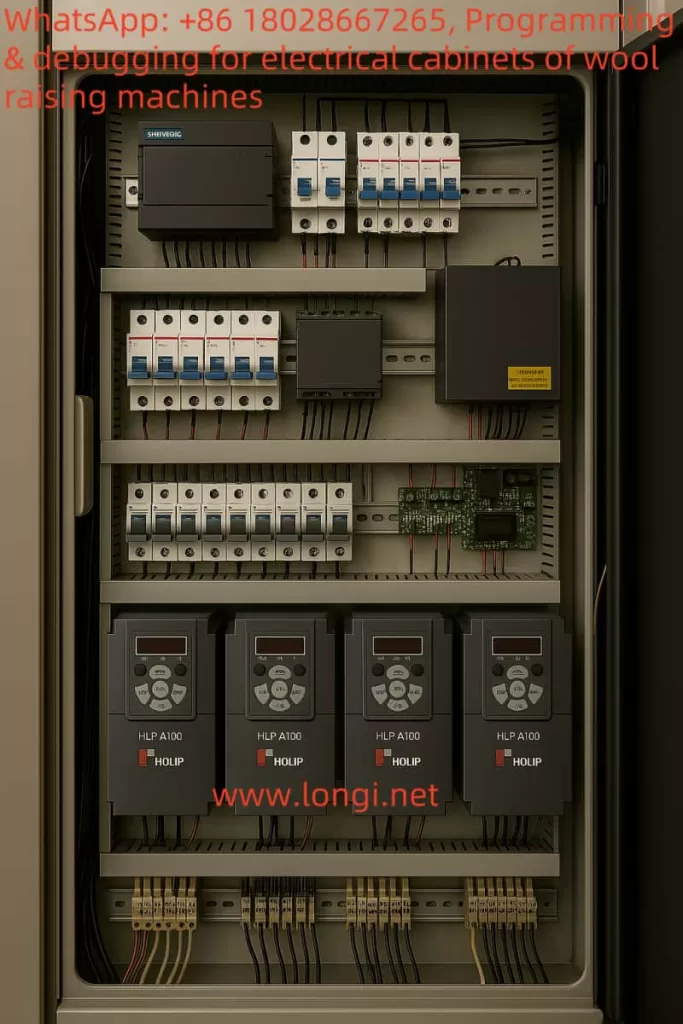
In the production process of textile factories, the napping machine (also known as the wire-drawing machine or yarn-extracting machine), as key equipment, undertakes the important tasks of stretching and homogenizing fibers. It is widely used in processes such as carding and yarn extraction. The Holip HLP-A100 inverter, as a general-purpose vector inverter, with its high reliability, wide range of applications, and rich control functions, can achieve precise control of the napping machine motor. This solution will comprehensively elaborate on the specific application of the Holip HLP-A100 inverter in the napping machine, covering the application positions, wiring methods, parameter settings, control logic, and providing descriptions of the electrical wiring diagram and control schematic. Additionally, equipment such as PLCs, touch screens, or industrial computers can be introduced according to requirements to achieve more advanced control functions.

I. Equipment Situation of the Napping Machine and Motor Function Analysis
The napping machine mainly stretches and homogenizes fibers through a series of rollers (or rolls). These rollers are usually driven by motors, and some roller groups may require independent motors to achieve precise speed control and ensure a constant drawing ratio (yarn-extracting ratio) of fibers between different rollers. The napping machine mainly includes the following key components and motor functions:
- Main Stretching Roller Motor: Assumes the main stretching function and requires variable speed control to adapt to different fiber types and production requirements.
- Auxiliary Roller Motor: Used for auxiliary stretching and fiber conveying, which may run synchronously with the main motor at a fixed speed ratio.
- Conveying Motor: Responsible for conveying fibers from upstream equipment (such as carding machines) to the napping machine and conveying the processed fibers to downstream equipment (such as spinning machines).
- Tension Control Motor: Some high-end napping machines are equipped with a dedicated tension control motor to maintain fiber tension and ensure production quality.
The motors of the napping machine are usually three-phase asynchronous motors with a power range of 1.5kW – 15kW, depending on the machine size and production capacity. This solution is based on the design of a main stretching roller motor with a power of 4kW.
II. Key Features and Specifications of the Holip HLP-A100 Inverter
The Holip HLP-A100 inverter, as a general-purpose vector inverter, is suitable for various motor control needs in the industrial field. Below are its key features and specifications (based on the official manual):
| Category | Details |
|---|---|
| Power Range | 0.75kW – 220kW (models such as HLP-A100001143 to HLP-A100022043) |
| Voltage Range | Three-phase 380 – 440V/440 – 480V, 50/60Hz |
| Control Modes | Speed open loop, process closed loop, torque open loop |
| Digital Inputs/Outputs | 4 digital inputs (DI1 – DI4), 2 digital outputs (DO1 – DO2), 2 relay outputs (KA – KB, FA – FB – FC) |
| Analog Inputs/Outputs | VI (0 – 10V/4 – 20mA), AI (0 – 10V/4 – 20mA), AO (0 – 20mA/4 – 20mA) |
| Pulse Inputs/Outputs | Pulse input (0.001 – 100.0KHz), pulse output (0.001 – 5.0KHz) |
| Communication Protocol | Modbus RTU (address range 1 – 247, baud rate 2400 – 38400) |
| Special Functions | Swing function, cascade control, winding control, mechanical braking, multi-speed control, etc. |
| Environmental Adaptability | Maximum altitude 1000m (output power or temperature must be reduced when exceeding this limit) |
This solution selects a model suitable for a 4kW motor from the HLP-A100 series, such as HLP-A100004043 (the specific model needs to be confirmed according to the manual).
III. Inverter Application Solution Design
3.1 Application Position
The Holip HLP-A100 inverter is mainly applied to the main stretching roller motor of the napping machine to achieve variable speed control of the main stretching roller. If the napping machine has multiple roller groups, multiple HLP-A100 inverters can be used, and cascade control can be implemented to achieve synchronous operation between different rollers and ensure a constant drawing ratio.
3.2 Wiring Method
3.2.1 Main Circuit Wiring
- Main Circuit Terminals:
- R, S, T: Connect to the three-phase AC power supply (380V/50Hz).
- U, V, W: Connect to the motor output terminals.
- PE: Grounding terminal, which must be connected to a reliable ground.
- Brake Circuit (if required):
- +UDC, -UDC: Connect to the brake resistor (the resistance value is selected according to the manual, usually 0.15 – 0.4Ω).
3.2.2 Control Circuit Wiring
- Digital Inputs (DI):
- DI1: Forward Run.
- DI2: Stop.
- DI3: Reverse Run (if required).
- DI4: Other auxiliary functions (such as emergency stop).
- Analog Inputs (AI):
- AI1: Speed reference signal (e.g., provided by an external potentiometer or PLC).
- Relay Outputs (Relay):
- KA – KB: Fault alarm output.
- FA – FB – FC: Running status indication.
- Communication Interface (RS485):
- RS+, RS-: Connect to the communication port of the PLC or touch screen.
3.2.3 Wiring Diagram Description
[Three-phase Power Supply] — R, S, T — [Holip HLP-A100 Inverter] — U, V, W — [Main Stretching Roller Motor]
[Ground] — PE — [Holip HLP-A100 Inverter]
[External Control Signal] — DI1(DI2/DI3/DI4) — [Holip HLP-A100 Inverter]
[Speed Reference Signal] — AI1 — [Holip HLP-A100 Inverter]
[Fault Alarm] — KA – KB — [Alarm Light or PLC]
[Running Status] — FA – FB – FC — [Indicator Light or PLC]
[Communication] — RS+, RS- — [PLC/Touch Screen]
3.3 Parameter Settings
Parameter settings are crucial for ensuring the normal operation of the inverter. Below are the typical parameter settings for the main stretching roller motor of the napping machine (based on the HLP-A100 manual):
3.3.1 Basic Parameters
- C01. Configuration Parameters
- C01.00 Configuration Mode: Set to “Speed Open Loop”.
- C01.20 Motor Rated Power: Set to 4.0kW.
- C01.21 Motor Rated Voltage: Set to 380V.
- C01.22 Motor Rated Current: Set according to the manual or motor nameplate (e.g., 7.8A).
- C01.23 Motor Rated Frequency: Set to 50Hz.
- C01.24 Motor Slip: Set according to the motor parameters (usually 1% – 5%).
3.3.2 Reference and Ramp Parameters
- C03. Reference/Ramp Parameters
- C03.03 Maximum Reference: Set to 50.0Hz (or adjust according to actual requirements).
- C03.04 Minimum Reference: Set to 0.5Hz (to avoid crawling at low speeds).
- C03.05 Acceleration Time 1: Set to 5.0 seconds (adjust according to production requirements).
- C03.06 Deceleration Time 1: Set to 5.0 seconds (adjust according to production requirements).
3.3.3 Digital Input/Output Parameters
- C05. Digital Input/Output Parameters
- C05.00 DI1 Function: Set to “Forward Run”.
- C05.01 DI2 Function: Set to “Stop”.
- C05.02 DI3 Function: Set to “Reverse Run” (if required).
- C05.10 DO1 Function: Set to “Running Status”.
3.3.4 Analog Input/Output Parameters
- C06. Analog Input/Output Parameters
- C06.99 AI1 Function: Set to “Frequency Command”.
3.3.5 Cascade Control Parameters (if synchronous control is required)
- C25. App. Functions Cascade Parameters
- If multiple motors need to be synchronized, the main inverter can be set as the master, and the auxiliary inverters can be set as slaves, with the frequency ratio set.
3.4 Advanced Control Solution: Introducing PLC and Touch Screen
To achieve more advanced control and a user interface, a PLC and touch screen can be introduced. Below is the recommended solution:
3.4.1 PLC Selection
Select a PLC that supports the Modbus RTU protocol, such as the Siemens S7-200 series or Schneider Modicon series. The PLC is responsible for handling logic control, such as start, stop, speed setting, and fault handling.
3.4.2 Touch Screen Selection
Select a touch screen that supports Modbus RTU, such as the Weintek MT8071i series. The touch screen is used for the user interface, providing start/stop buttons, speed setting sliders, status displays, etc.
3.4.3 PLC and Touch Screen Wiring
- The PLC is connected to the inverter via RS485 communication.
- The touch screen is connected to the PLC’s communication port or directly to the inverter (if the touch screen supports direct control).
3.4.4 PLC Program Design
- Use the PLC’s Modbus function blocks to read the inverter’s status (such as running status, output frequency).
- Use the PLC’s Modbus function blocks to write control commands to the inverter (such as start, stop, frequency setting).
- Logic can be added to the PLC program, such as:
- When the start button is pressed, send the start command after checking safety conditions.
- When the speed setting changes, update the inverter’s frequency command.
3.4.5 Touch Screen Design
- Main Screen: Display the current speed, running status, and fault information.
- Control Buttons: Start, stop, emergency stop.
- Parameter Setting Page: Allow adjustment of acceleration/deceleration time, maximum/minimum frequency, etc.

IV. Control Schematic Description
Below is a description of the overall control schematic of the system:
[Three-phase Power Supply] — [Holip HLP-A100 Inverter] — [Main Stretching Roller Motor]
[External Control Signal] — [Holip HLP-A100 Inverter] — [PLC]
[PLC] — [Touch Screen]
[PLC] — [Other Auxiliary Devices (such as alarm lights, indicator lights)]
V. Summary and Key Notes
The application of the Holip HLP-A100 inverter in the napping machine can significantly improve production efficiency and product quality. Through precise speed control and synchronization functions, it ensures the uniform stretching of fibers. Below are the key notes:
- Model Selection: Select the appropriate inverter model according to the power of the napping machine motor.
- Wiring: Ensure correct connection of the main circuit and control circuit, paying attention to grounding and shielding.
- Parameter Settings: Adjust parameters such as acceleration/deceleration time and maximum/minimum frequency according to actual production requirements.
- Safety Protection: Ensure that the emergency stop function works normally and comply with relevant safety standards.
- Advanced Control: Achieve more flexible control and monitoring through PLC and touch screen.
Through the implementation of this solution, the efficient operation of the napping machine can be achieved, providing more reliable production assurance for textile factories.
