1. Introduction
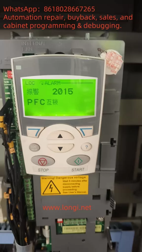
In modern industrial automation systems, the inverter (VFD) plays a crucial role in controlling speed, constant pressure water supply, fan control, and other applications. However, during actual operation, inverters often encounter various types of alarms that affect system stability and operational efficiency. Among these alarms, Alarm 2015 – PFC Interlock Fault, is a common issue in ABB ACS510 inverters, especially in applications where PFC control functionality (pump-fan control) is used.
This article will conduct an in-depth analysis of the root causes of Alarm 2015 in ABB ACS510 inverters, explain the working principle of PFC interlock functionality, and provide practical troubleshooting steps. By combining inverter control logic, parameter configurations, and field wiring, we will explore effective solutions to this alarm issue. This article aims to help readers thoroughly understand the mechanisms behind PFC interlock faults and how to address them, ensuring stable operation of the inverter system.
2. Overview of Alarm 2015 PFC Interlock Fault
1. Meaning and Trigger Conditions of Alarm 2015
Alarm 2015 is a typical alarm code in ABB ACS510 inverters, indicating a PFC Interlock fault. When the system detects that the interlock condition is not satisfied, the inverter will stop the motor and display Alarm 2015 on the control panel. This alarm code is primarily used in multi-pump constant pressure water supply systems and other similar applications, ensuring that the switching order and status of motors are properly controlled to prevent system conflicts or equipment damage.
The triggering conditions for PFC interlock alarms are usually as follows:
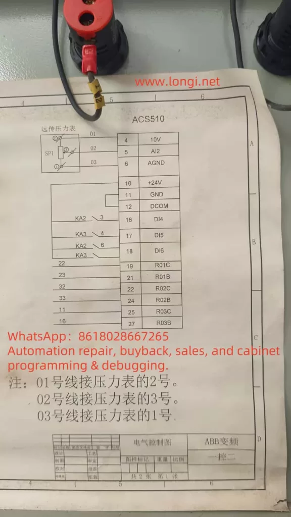
- Abnormal Interlock Input Signals: When the interlock signals received by the inverter (via digital inputs such as DI4, DI5, DI6, etc.) do not meet the expected conditions, the inverter considers a conflict or fault and triggers Alarm 2015.
- Motor Status Conflicts: If one pump is running and the inverter attempts to start another pump without releasing the interlock condition, the alarm will be triggered.
- Incomplete Equipment Switching: During automatic switching, if relevant devices (such as the bypass contactor, auxiliary relays, etc.) do not properly disconnect, the interlock signal will not reset, causing the inverter to detect an inconsistency and generate the alarm.
Alarm 2015 indicates that the inverter has not correctly recognized or executed the interlock logic, and it typically involves issues with wiring, parameter configuration, or the status of the equipment.
2. Overview of PFC Control Function
The PFC (Pump Fan Control) function is a commonly used control mode in ABB inverters for applications such as constant pressure water supply. It adjusts the operating frequency of the pumps and switches between variable frequency and fixed frequency operation to achieve automatic switching and load balancing between multiple pumps. In order to ensure the safe and stable operation of the system, the PFC function typically relies on interlock mechanisms to ensure that the switching of the inverter and the fixed frequency power supply, as well as the start and stop status of the pumps, are coordinated.
In systems using PFC control, the inverter monitors the operating status of multiple pumps and uses digital inputs (DI) and relay outputs (RO) to determine when to start or switch motors and adjust the system’s operational status in real-time. If any of these signals are abnormal or the equipment status does not match, the inverter will generate Alarm 2015.
The core purpose of the PFC interlock function is to prevent two pumps from running simultaneously under inappropriate conditions, avoiding equipment damage or energy loss. Its proper operation depends on correct wiring, reasonable parameter configuration, and the integrity of the equipment.
3. Root Cause Analysis of Alarm 2015 Triggering
1. Wiring Issues in the Control Circuit
According to ABB inverter design logic, Alarm 2015 is typically triggered by abnormal interlock input signals (DI4, DI5, DI6, etc.). Improper wiring or equipment failures can lead to the loss or incorrect reception of these signals, causing Alarm 2015 to be triggered. Common wiring issues include:
- Incorrect Wiring of Contact Auxiliary Contacts: The PFC control function depends on the auxiliary contacts (normally closed contacts) of the contactors to monitor the motor’s operational status. If the wrong type of contact (normally open) is used, or if the auxiliary contacts of the contactors do not reset properly, this can result in abnormal DI input signals and trigger the alarm.
- Failure to Correctly Feed Back Digital Input Signals: DI4, DI5, and other digital input signals should be connected through normally closed auxiliary contacts of contactors and thermal relay contacts. If these contacts are omitted or not securely connected, it may result in the loss of interlock signals and trigger Alarm 2015.
2. Unstable Relay Output Signals
The PFC control function in ABB ACS510 inverters relies on relay outputs (RO1, RO2, RO3, etc.) to control the starting and stopping of motors. If the relay output signals are unstable or configured incorrectly, Alarm 2015 can be triggered. Common issues with relay outputs include:
- Conflicting Relay Output Signals: In some system designs, RO1 and RO2 may be used to control the start and stop of two pumps. If these two relay outputs conflict and prevent the pumps from switching in the expected order, Alarm 2015 will be triggered.
- Relay Contact Failure: If the normally open or normally closed contacts of a relay are damaged due to wear or malfunction, they may fail to operate properly, causing the interlock circuit to remain open or closed, triggering the alarm.
3. Parameter Configuration Issues
Alarm 2015 can also be caused by issues in the inverter’s parameter configuration. Below are some possible parameter-related problems that may lead to the alarm:
- Incorrect Configuration of Interlock Parameters: In PFC control, parameters 8120 (INTERLOCKS) and 8121 (REG BYPASS CTRL) control the startup and switching of interlock logic. If these parameters are configured incorrectly, the inverter may not correctly recognize interlock signals, triggering Alarm 2015.
- Unreasonable Automatic Switching Interval: If the automatic switching interval (parameter 8118) is set too short or too long, the system may become unstable during switching, triggering the alarm. The switching interval should be adjusted according to the actual load and system requirements.
4. Equipment Status Conflicts
If there is a fault with a pump or it does not stop as expected, Alarm 2015 can also be triggered. Common equipment status conflicts include:
- Pump Not Stopping: If a pump that is running has not completely stopped, or if the bypass contactor has not disconnected, the inverter will not be able to start a new pump, triggering Alarm 2015.
- Equipment Fault: If a pump experiences an overload or fault, the inverter will detect this and automatically stop, displaying Alarm 2015.
4. Solutions to Alarm 2015
1. Check Wiring and Hardware
First, check the wiring in the control circuit to ensure that all auxiliary contacts, thermal relay contacts, and contactor contacts are connected correctly to the appropriate DI input terminals. The common wiring checks are as follows:
- Check DI4 and DI5 Wiring: Ensure that DI4 (variable-speed pump interlock) and DI5 (auxiliary pump interlock) are connected in series with the normally closed auxiliary contacts of the bypass contactor and thermal relay contacts, ensuring that DI is “ON” when the pumps are not running.
- Check Relay Output Signals: Check whether the relay output contacts (RO1, RO2, RO3) are functioning correctly and whether they can start and stop the pumps according to the actual load status.
2. Adjust Parameter Configuration
Next, check the relevant parameter settings in the inverter, particularly the following key parameters:
- Check Parameter 8120 (INTERLOCKS): Ensure that this parameter is set to an appropriate value, typically 4, meaning that the interlock signals are distributed from DI4.
- Check Parameter 8121 (REG BYPASS CTRL): This parameter controls the bypass function for the variable-speed pump. Ensure it is set to match the field requirements. If bypass control is not needed, set this parameter to 0.
- Check Parameter 8118 (Automatic Switching Interval): Adjust the automatic switching interval according to the system’s load requirements to avoid frequent or prolonged switching that could cause instability.
3. Eliminate Equipment Faults
If the wiring and parameter configuration are correct, check the equipment status. The following methods can be used to check:
- Check the Status of the Pump: Ensure that the pumps are completely stopped before switching, and that the bypass contactor has been disconnected.
- Check for Pump Overload Protection: Ensure that the pump is not overloaded or faulty. If necessary, inspect and maintain the motors to eliminate faults that could trigger Alarm 2015.
4. Perform Simulation Tests
Perform manual tests to simulate different operating conditions and observe whether the inverter responds correctly without triggering an alarm. For example, manually control the input signals of DI4, DI5, and DI6 to see if the inverter starts the motors correctly and switches them without triggering Alarm 2015.
5. Conclusion
ABB ACS510 Inverter Alarm 2015 (PFC Interlock Fault) is a common fault in multi-pump constant pressure water supply systems. Through an analysis of Alarm 2015, we identified that the root cause is usually related to abnormal interlock signals, wiring issues, relay output conflicts, incorrect parameter configurations, or equipment faults. The solutions to this problem include checking control circuit wiring, adjusting parameter settings, eliminating equipment faults, and performing simulation tests.
By performing proper troubleshooting and making the necessary adjustments, Alarm 2015 can be effectively eliminated, ensuring the stable operation of the system. In future applications, operators should regularly check the control circuit, maintain the equipment, and ensure that the inverter operates stably to avoid recurring alarms.
I hope this article provides valuable assistance to ABB inverter users, helping them understand the causes of PFC interlock faults and how to address them.