I. How to Achieve Forward/Reverse Rotation and Speed Control via External Terminals
The VACON NX series of frequency converters allows for straightforward forward/reverse rotation and speed control via external terminals. Here’s how to achieve this:
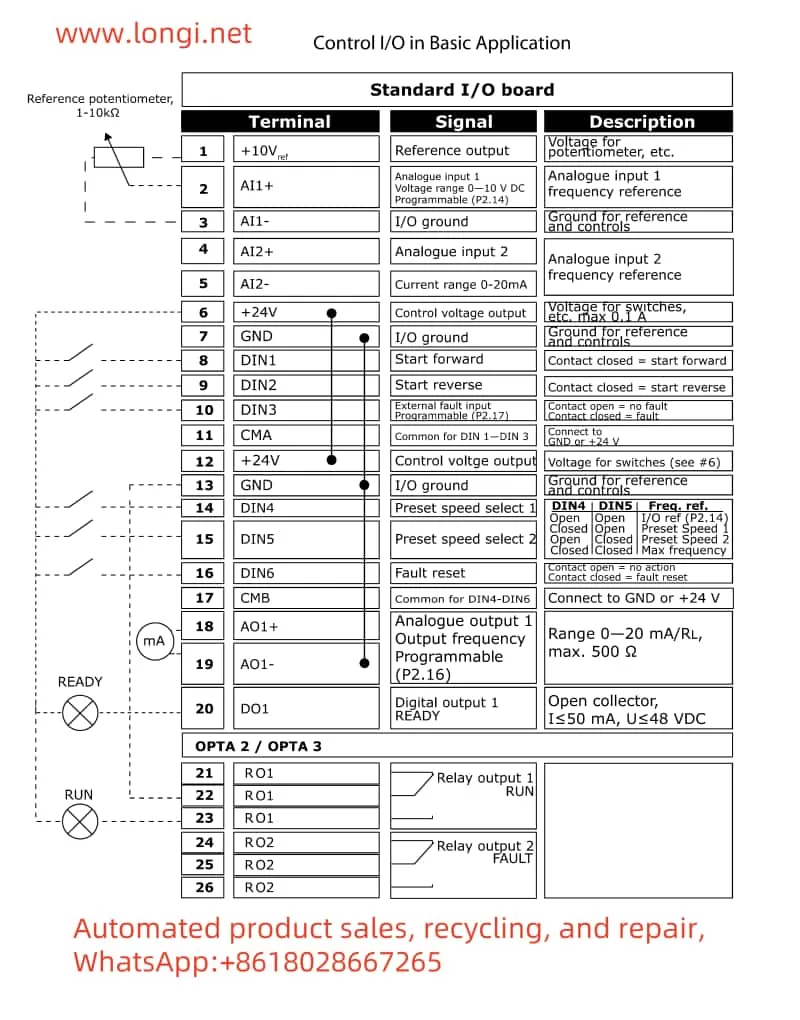
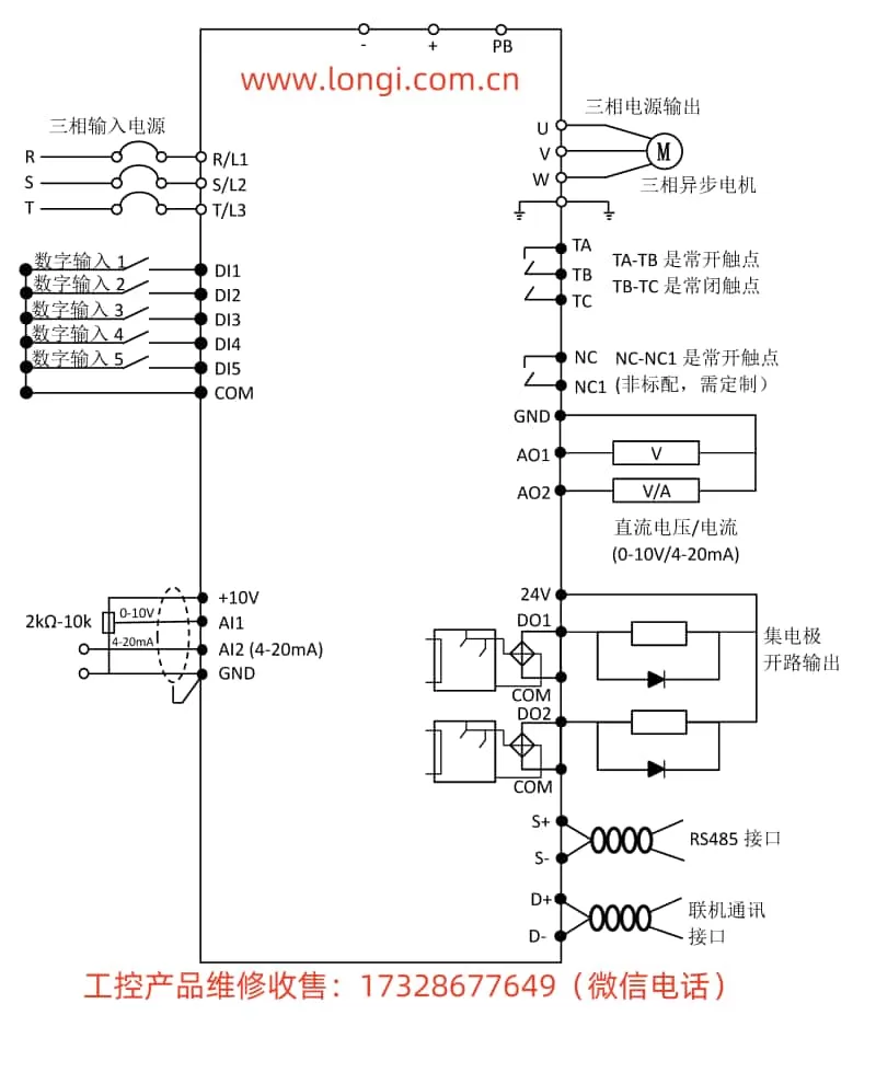
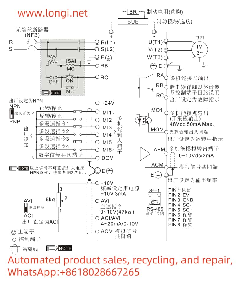
- Terminal Connections:
- Forward/Reverse Control:
- Forward rotation is typically connected to the DI1 (forward start) terminal of the frequency converter.
- Reverse rotation is typically connected to the DI2 (reverse start) terminal.
- Note that different NX series models may have different terminal numbers; refer to the specific model’s user manual for confirmation.
- Potentiometer Speed Control:
- Connect the three terminals of the potentiometer to the AI1 (analog input 1), GND (ground), and +10V (analog input positive power) terminals of the frequency converter, respectively.
- Forward/Reverse Control:
- Parameter Settings:
- Forward/Reverse Parameters:
- Set the control source to external terminal control and ensure that the DI1 and DI2 functions are correctly configured for forward and reverse rotation.
- Potentiometer Speed Control Parameters:
- Set AI1 as the frequency reference source.
- Adjust the input range of AI1 as needed to ensure that the potentiometer’s output range matches the frequency converter’s frequency range.
- Forward/Reverse Parameters:
II. Characteristics of PID Function and Its Application in Constant Pressure Control of Water Pumps
The PID function of the VACON NX series frequency converter is highly capable and suitable for various automatic control applications. Here are its key features and how to apply it to constant pressure control of water pumps:
- PID Function Characteristics:
- Supports multiple PID control modes, including standard PID and sleep/wake-up functions.
- Flexible PID parameter configuration via external terminals or fieldbus.
- Provides comprehensive monitoring and alarm functions to ensure stable system operation.
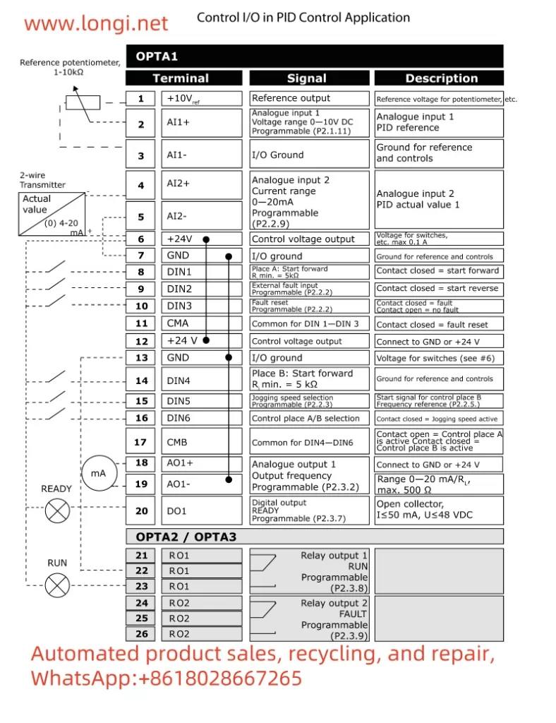
- Application in Water Pump Constant Pressure Control:
- Terminal Connections:
- Connect the output signal of the pressure sensor to the AI1 (analog input 1) terminal of the frequency converter.
- Connect other control terminals as needed, such as start and stop.
- Parameter Settings:
- Set AI1 as the actual value input for PID control.
- Configure the reference value for the PID controller (target pressure value).
- Adjust the PID parameters (proportional, integral, derivative) to achieve optimal control performance.
- Set the sleep/wake-up function as needed to save energy.
- Terminal Connections:
III. Fieldbus Protocol and Communication with Siemens PLC
The VACON NX series supports multiple fieldbus protocols, including Profibus, Modbus, etc., facilitating communication with various PLCs. Here’s how to set up communication with a Siemens PLC:
- Fieldbus Protocol:
- The NX series supports multiple fieldbus protocols; users can select the appropriate protocol based on actual needs.
- Communication with Siemens PLC:
- Wiring:
- Connect the frequency converter’s fieldbus interface to the corresponding interface of the Siemens PLC using a dedicated fieldbus communication cable.
- Parameter Settings:
- Configure fieldbus parameters in the frequency converter, including station address, baud rate, etc.
- Configure corresponding communication parameters in the Siemens PLC to ensure compatibility with the frequency converter.
- Program the PLC to send start, stop, and speed adjustment commands to the frequency converter via the fieldbus.
- Wiring:
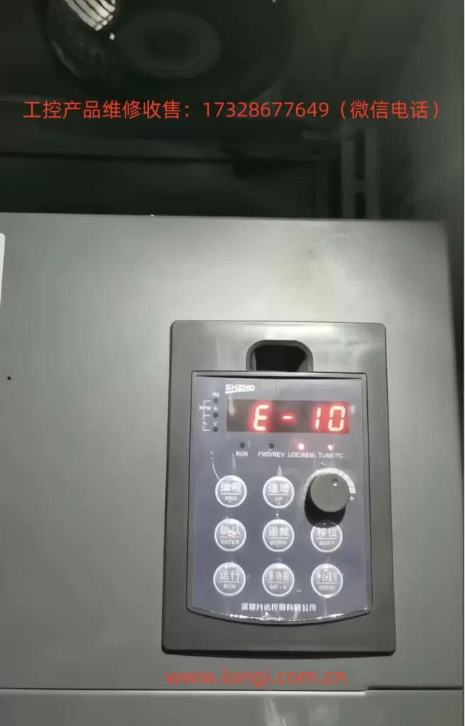
IV. Fault Code Meaning Analysis and Troubleshooting
The VACON NX series provides comprehensive fault codes to help users quickly locate and resolve issues. Here are some common fault codes, their meanings, and troubleshooting methods:
- F1: Overcurrent Fault
- Meaning: The output current of the frequency converter exceeds the set value.
- Troubleshooting: Check for motor overload, cable short circuits, and correct frequency converter parameter settings.
- F2: Overvoltage Fault
- Meaning: The DC bus voltage of the frequency converter is too high.
- Troubleshooting: Check for stable input voltage and proper operation of the braking resistor.
- F5: Charging Switch Fault
- Meaning: The internal charging switch of the frequency converter is abnormal.
- Troubleshooting: Check the charging switch and related circuits for proper functioning.
V. Conclusion
The VACON NX series user manual provides detailed usage guides and parameter setting instructions, helping users quickly get started and implement various complex control functions. Through this guide, users should now have a comprehensive understanding of how to achieve forward/reverse rotation and speed control via external terminals, the characteristics and application of the PID function, fieldbus protocol and communication with Siemens PLC, as well as the meanings and troubleshooting methods of fault codes. In practical applications, users should flexibly configure parameters and wiring based on specific needs and site conditions to achieve optimal control performance.