Posted on Leave a comment

In-Depth Analysis of Alarms 1080 (Trace Data Save) in Siemens SINAMICS S120 Drives


1. Introduction

In modern industrial automation, Siemens SINAMICS S120 drives are widely employed across various applications such as CNC machine tools, textile machinery, printing presses, papermaking equipment, robotics, and other sectors demanding high dynamic performance and precision. SINAMICS S120 offers a modular design, advanced control capabilities, and a robust diagnostic system. When an abnormal condition occurs or when the drive simply wishes to notify the user of a particular state, it displays corresponding alarm or fault codes on the Basic Operator Panel (BOP), in the STARTER/TIA Portal software, or on an external HMI (Human-Machine Interface).

Among the many potential fault and alarm messages, Alarms 1080—often accompanied by the text “comp trace data save”—commonly appears in actual usage. Some engineers or first-time users of S120 may misinterpret this alarm as a sign of major damage or serious malfunction. However, Alarms 1080 is typically an information-level or process-level alert, indicating that the drive is saving trace (data logging) information. It is neither a hardware breakdown nor a critical fault demanding immediate shutdown. Understanding and properly handling this alarm is important for maintaining the stability of the drive system and prolonging equipment life. This article will thoroughly explain Alarms 1080’s background, implications, and recommended actions.
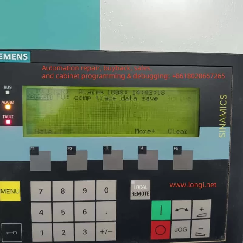

alarms 1808

2. Definition and Background of Alarms 1080

2.1 Overview of the Trace Function

Siemens SINAMICS S120 includes a built-in Trace (data logging or “oscilloscope”) feature. This function records specified operating parameters or signals (e.g., current, speed, position feedback, torque commands) within the drive’s memory. When the Trace function is enabled—either manually by the user in the engineering software (STARTER or TIA Portal) or triggered automatically by certain system conditions—these signals are sampled at set intervals or in response to defined triggers. The sampled data is then stored in the drive’s internal memory or on a connected storage card (such as a CF card).

Once the sampling cycle or trigger condition is completed, the drive writes or finalizes the captured data. During this process, the drive issues a notification to indicate that it is actively saving data. This valuable dataset can later be analyzed to optimize control parameters or diagnose intermittent or complex errors.

2.2 What Alarms 1080 Signifies

When you see Alarms 1080 with a description along the lines of “comp trace data save” or “Trace data is being saved,” it specifically indicates that the drive is performing the data save operation for an active Trace task.

  • This message does not imply hardware damage or a system crash.
  • It is typically a “system event” or “user-level” notification that does not disrupt the drive’s primary function.

2.3 How It Differs from Fault Codes

Unlike “Fault” codes (e.g., F07802, F30003) prefixed with “F,” which usually shut down or block the drive until reset, an alarm such as Alarms 1080 does not force the drive into a faulted or disabled state. Serious faults typically demand manual acknowledgment or system logic to reset them; meanwhile, Alarms 1080 is more akin to an informational prompt. Once data saving completes and no other higher-level issues exist, the system will clear or deactivate the alarm automatically.


3. Common Causes and Scenarios

In practice, Alarms 1080 (“comp trace data save”) most often arises from these scenarios:

  1. Manually Enabled Trace During Commissioning
    In many cases, an engineer sets up a Trace task in STARTER, TIA Portal, or directly on the panel to diagnose specific motor or drive behavior. For example, if you want to observe speed-loop responses or current-waveform patterns, you configure sampling frequency, trigger conditions, and the signals to track. As soon as the sampling finishes, the drive writes the data to storage, resulting in Alarms 1080.
  2. Automatic Background Trace
    Some drive configurations automatically initiate the Trace function for advanced monitoring or “fault logging.” When the system detects certain threshold conditions or a fault event, the drive begins collecting data. Once the event is captured, it proceeds to save it, displaying Alarms 1080 in the process.
  3. Leftover Trace Settings
    In some projects, the Trace function was used at one point but never deactivated. Even after the main commissioning is done, the drive may still be periodically recording data and subsequently saving it, inadvertently causing recurring Alarms 1080 messages. Though typically benign, these messages might raise questions among less-experienced personnel.
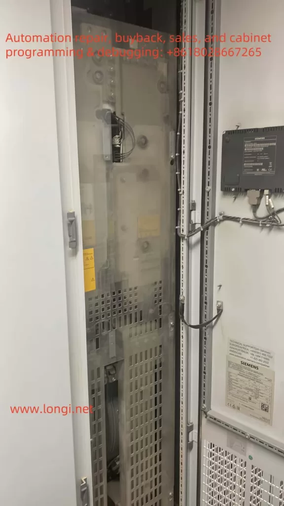
S120 drives

4. Impact on System Operation

Because Alarms 1080 is an informational or process-level alert, it does not necessarily prevent normal drive operation or motor control, as long as there are no simultaneous major fault codes. However, keep in mind the following:

  1. Do Not Interrupt Power During Saving
    If the drive is in the middle of saving Trace data and power is lost or intentionally shut off, it may lead to incomplete data or, in rare cases, corruption of the storage medium. In general, it is best to avoid powering down the drive while Alarms 1080 is active unless absolutely necessary.
  2. Resource Consumption
    The Trace function may consume a portion of the drive’s internal resources, including CPU and memory. Although typically minimal, high sampling rates combined with large data sets can create significant overhead. If the user no longer needs Trace data, disabling it can free up resources.
  3. Parallel Occurrences with Faults
    If a severe drive fault (e.g., F07802 “Infeed Not Ready”) appears alongside Alarms 1080, the fault should take priority for troubleshooting. Alarms 1080 in that case merely indicates that trace data related to the fault was captured or saved, but it is not the cause of the fault itself.

5. Handling and Disabling Methods

When you see Alarms 1080 on the drive, and you confirm that a Trace save is in progress, you can use the following approaches to manage or eliminate it:

  1. Wait for the Save to Complete
    Typically, the drive only needs a short interval—ranging from a few seconds to maybe a minute—for large data sets—to store the captured Trace data. The alarm will then disappear on its own once the operation finishes.
  2. Deactivate or Remove Trace Tasks
    If data logging is no longer required, you can open the Trace or Recording screen in STARTER or TIA Portal, locate any active Trace configurations, and disable or delete them.
    • Certain drive operator panels (like BOP20) may also allow you to view or halt ongoing Trace recordings if the firmware supports it.
  3. Check Storage Space and Write Permissions
    Occasionally, if the alarm persists, the storage medium (internal memory or CF card) might be full, write-protected, or otherwise inaccessible. Ensure you have enough free space or switch to a larger-capacity CF card if needed.
  4. Reset Alarms If Needed
    Usually, purely informational alarms clear automatically without requiring a reset. However, if Alarms 1080 coincides with an actual Fault, you may need to perform a fault reset (via the panel or a higher-level controller) after addressing the underlying issue.

6. Common Questions and Answers

Q1: “Does the presence of Alarms 1080 mean the drive is damaged?”
A1: Not at all. Alarms 1080 almost always indicates that the drive is recording or saving Trace data, not that any component has malfunctioned. If no additional serious alarms or faults are active, the system can continue operating normally.

Q2: “Will repeatedly seeing Alarms 1080 negatively affect the system?”
A2: In most cases, no. It simply appears whenever trace-saving occurs. Unless you are sampling enormous volumes of data at high frequencies, system performance typically remains unaffected. If you do not need the Trace feature, consider disabling it to keep messages streamlined.

Q3: “How do I check Trace configurations or the storage location?”
A3: Within STARTER or TIA Portal, navigate to the corresponding drive object, and look for “Trace” or “Recording” in the function tree. There, you can view and edit active tracing tasks. On certain operator panels, you might find a Diagnostics → Trace Logs menu that shows ongoing traces and storage status.

Q4: “What else can the Trace function be used for?”
A4: Beyond fault diagnosis, the Trace feature is invaluable for capturing transient oscillations, optimizing control loops (like speed-loop gains or filter time constants), and logging multiple signals simultaneously. It helps improve control accuracy and pinpoint root causes of sporadic or short-lived anomalies.


7. Case Study

Consider a textile production line where an engineer needs to diagnose oscillations in the S120 drive. By enabling two Trace channels (one for current loop, one for speed loop) at a high sampling rate, the system collected large volumes of data. While saving these data sets, “Alarms 1080: comp trace data save” appeared repeatedly on the drive’s screen. Initially, on-site maintenance personnel feared a serious error; however, it quickly became clear that the drive was simply finalizing the recording.

Once the trace was stored, Alarms 1080 cleared by itself. Analyzing the newly captured data, the engineer discovered a PID tuning issue. By fine-tuning the relevant parameters, they significantly reduced mechanical vibration. This real-world experience illustrates how Alarms 1080 is part of a normal diagnostic workflow and can be harnessed for performance improvements rather than being an indication of a critical failure.


8. Conclusion

In summary, Alarms 1080 (“comp trace data save”) in the Siemens SINAMICS S120 drive primarily indicates the system is saving Trace data—a process-level or informational message rather than a hardware or software malfunction. Proper use of the Trace function can substantially enhance commissioning and fault diagnosis, making it possible to observe internal drive states and parameter changes in great detail. If you do not need data logging, you can disable or remove the trace configuration to prevent recurrent alarms.

If a severe fault (e.g., an “Fxxxx” code) accompanies Alarms 1080, prioritize investigating the fault itself. Ensure power and wiring integrity, confirm that no IGBT or module fault exists, and only then determine whether to proceed with or discontinue trace logging. But in the absence of critical errors, Alarms 1080 simply signals that the drive is working as intended to capture and save valuable diagnostic data.

By correctly recognizing Alarms 1080 and using it appropriately, maintenance and commissioning personnel can leverage the drive’s powerful built-in diagnostic capabilities without undue worry. This alarm can assist with targeted data capture, enabling users to optimize performance and quickly resolve intermittent failures. We hope this article clarifies the nature of Alarms 1080 in SINAMICS S120 and helps you confidently manage and benefit from its Trace functionality in real-world industrial scenarios.

Posted on Leave a comment

Application Scheme of HLP-C100 Inverter for Desiccant Packaging Machine


I. Overall Concept

  1. Application Points and Functions
    In a desiccant packaging machine, there are often multiple drive motors, such as a feeding motor, a sealing motor, a blower/fan motor, a conveyor motor, and so on. If you are focusing on the “desiccant-blowing” or “air-blowing” process, you can apply the HLP-C100 inverter in the following situations:
    • Blower/Fan Motor: By using the inverter to control air volume or blowing speed, you can flexibly adjust airflow according to packaging speed or desiccant characteristics.
    • Conveying/Feeding Motor (if necessary): You can achieve more precise control of the speed at which desiccant moves, preventing blockage or spillage.
    • Other Auxiliary Mechanisms (e.g., stirring, lifting, rotating, etc.): Based on your needs, you can also equip these with an inverter to implement multi-step speed or jog functionalities.
  2. Control Method Selection
    • To allow flexible speed adjustment, operators may directly set the speed on the inverter’s front panel using the built-in knob (local control mode), or use an external analog signal (0–10V/4–20mA from a PLC or industrial PC) as a remote speed reference.
    • If the machine requires centralized automation control (e.g., unified operation from an HMI, production line linkage, recipe management), you can add a small PLC (e.g., Hailipu’s PLC, Mitsubishi FX series, Xinje, Delta, etc.) and an HMI (touch panel) to manage start/stop commands, frequency references, alarm display, and more.

Below, we address main circuit wiring, control circuit wiring, parameter settings, and how to select/connect a PLC/HMI.


II. Main Circuit Wiring

  1. Motor-to-Inverter Connection
    • Inverter Output Terminals: U, V, W → Connect to the three-phase terminals of the blower/fan motor (if you have a single-phase motor, this will not be suitable unless you use a model that supports single-phase output).
    • Inverter Input Terminals: R, S, T → Connect to the three-phase AC supply (for single-phase 220 V models, connect to R and T).
    • Ground Terminal PE: Must be reliably grounded to prevent leakage, interference, and induced voltages.
    Refer to the “3.3 Main Circuit Wiring Diagram” in the manual.
    For smaller motor power ratings (e.g., 0.75 kW to 1.5 kW), the HLP-C100 series is usually sufficient. Ensure that the motor’s rated power, voltage, and current match the inverter’s specifications, leaving some margin.
  2. Peripheral Protection and Input-Side Components
    • Circuit Breaker (Air Switch): Selected based on the inverter’s rated input current (see “3.2.1 Air Switch, Fuse, Contactor Selection” in the manual) to cut power promptly under overcurrent or other serious faults.
    • AC Contactor (optional): Avoid using it too frequently for starting/stopping the inverter. Typically, it’s only used for maintenance or emergency power-off situations.
    • Input Reactor/EMI Filter (optional): If the site has harmonic issues or other sensitive equipment, consider adding an input reactor or EMI filter on the supply side to reduce higher-order harmonics and electromagnetic interference.
  3. Brake Unit and Brake Resistor (optional)
    For a “blower” load, inertia is usually not large, and fast, frequent deceleration is rarely required, so you typically do not need an external brake unit/resistor. But if this inverter is used with higher-inertia loads or requires rapid stops (such as certain conveying or feeding mechanisms), you may consider using the built-in or external brake unit plus an appropriately sized brake resistor.
  4. Main Circuit Diagram (Text Example) Power R ——┐ │ Power S ——┤—— [Circuit Breaker] —— [HLP-C100 Inverter] —— U —— Motor (UVW) │ V Power T ——┘ W Inverter PE ———— Ground (Earth) (The above example shows a three-phase 380 V connection; for single-phase, omit S and connect R/T to the live/neutral wires.)

III. Control Circuit Wiring

Control circuit wiring determines how the inverter receives start/stop, direction, and frequency commands, and how it outputs fault and run signals. If you need to use a PLC or external buttons for control, refer to the following.

  1. Digital Inputs (DI)
    • The HLP-C100 provides five digital input terminals (FOR, REV, DI1, DI2, DI3) configured as NPN by default (see “3.4 Control Circuit Wiring” in the manual).
    • Typically, FOR is set as the “forward run” command, REV as “reverse run” (if necessary), and the remaining DI1, DI2, DI3 can be set up for multi-step speed selection, emergency stop, reset, jog, etc.
    • For a blower needing only forward run and stop, you can place an external “START” button (normally open) and a “STOP” button (normally closed) to the respective terminals. For example:
      • FOR = Start (via a normally open button + 24 V power; pressing it gives a high-level signal to the inverter)
      • DI1 = Stop (via a normally closed button + 24 V; pressing it breaks the circuit, giving a low-level signal to stop)
      • Or you can assign “start-stop in one” to FOR (reverse logic).
  2. Analog Input (VI)
    • If you want to adjust blower speed remotely using an external analog signal (0–10 V / 4–20 mA from a PLC or sensor), wire the signal to VI and GND on the inverter.
    • In the parameters (e.g., C03.15, etc.), select “Reference Source 1 = VI,” and calibrate the range in C06.10~C06.19 to match your actual voltage or current signal.
  3. Relay Output (FA-FB-FC)
    • If you want a dry contact output from the inverter to indicate a fault or run status, set parameter C05.40 (Relay Output Function) to 9 (Fault), 5 (Running), etc. Then a PLC or external indicator can monitor the inverter state.
  4. Control Circuit Diagram (Text Example) [+24V] —— Start Button (NO) ——> FOR terminal on inverter —— Stop Button (NC) ——> DI1 terminal on inverter GND ---------------------------------> Inverter GND Analog: PLC AO(0-10V) ——> VI PLC AGND ——> GND Relay Output: FA-FB-FC (FB is common, FA is NC, FC is NO) (If you are only using the inverter’s keypad for start/stop and knob for speed, you can omit the digital inputs or just keep a dedicated emergency stop.)

IV. Key Parameter Settings (Example)

Suppose the motor is 0.75 kW, rated voltage 380 V, rated frequency 50 Hz, rated current 1.8 A (example). You want to control start/stop with external FOR and DI1, and 0–10 V analog for speed. Below are key configuration points (see the manual’s “Chapter 5–7: Function Parameter Table” and “Quick Application Guide” for details):

  1. Motor Parameters (Group 01)
    • C01.20 = Motor Power = 0.75 (kW)
    • C01.22 = Motor Rated Voltage = 380 (V)
    • C01.23 = Motor Rated Frequency = 50.0 (Hz)
    • C01.24 = Motor Rated Current = 1.80 (A)
    • C01.25 = Motor Rated Speed = 1440 (rpm) (example)
  2. Operating Mode
    • C01.00 = 0 (Open-loop speed)
  3. Reference Frequency and Acc/Dec (Group 03)
    • C03.03 = 50.00 (Max Reference; set to 50 if you want up to 50 Hz, or higher if you want 60 Hz, etc.)
    • C03.15 = 1 (Reference Source 1 = “Terminal VI”)
    • C03.41 / C03.42 = 5.0 s / 5.0 s (Acceleration/Deceleration time; adjust as needed for the blower’s inertia)
  4. Start/Stop & Direction Control (Group 05)
    • C05.10 (FOR Input Function) = 8 (“Start”)
    • C05.12 (DI1 Input Function) = 6 (“Stop, inverse logic”) or 46 (“Stop, normal logic”)
    • If reverse is not required, set C04.10 (Motor Run Direction) to 0 to allow only forward operation, preventing accidental reverse.
  5. Analog Input (Group 06)
    • C06.19 = 0 (Indicates VI is a voltage input)
    • C06.10 = 0.00, C06.11 = 10.00 (0–10 V corresponds to 0–50 Hz)
    • If you need a zero deadband, set C06.18 accordingly; if the input fluctuates too much, increase C06.16 (filter time), etc.
  6. Protections and Warnings
    • C04.58 = 0 (Motor phase-loss detection; set to 1 if you need it)
    • C14.01 = 5 (Carrier frequency, typically 4–6 kHz is fine; lower it if there’s high EMI)
    • Other defaults (overcurrent, overvoltage, overheat, external faults, etc.) already provide complete protection but can be tuned further if required.
  7. Other Common Functions
    • Multi-step Speed: Use DI1, DI2, DI3 in combination to set up multi-speed operation (e.g., fast, slow, jog).
    • PID Control: If you want to control blower pressure or airflow precisely, set C01.00=3 (Process Closed Loop) and configure the PID parameters in Group 07 along with a feedback sensor signal on VI.
    • Jog: Use C03.11 for jog frequency, and assign a DI (e.g., FOR or DIx) to “jog function.”

V. Using a PLC / Touch Screen / Industrial PC (If Needed)

  1. PLC Selection
    • For simpler requirements (start/stop, speed reference, minimal I/O), choose a low-end PLC (e.g., Hailipu, Delta, Xinje, Mitsubishi FX1S/FX3U, etc.).
    • For more comprehensive linkage (e.g., multi-station synchronization, multi-step speeds, fault interlocks), select a mid-range PLC with sufficient I/O.
    • Communication: The HLP-C100 features RS485 (Modbus RTU). If your PLC has RS485, you can connect them directly with twisted-pair wiring. Through PLC registers, you can read/write the inverter’s operating status, fault info, frequency commands, etc.
  2. Touch Screen / HMI / Industrial PC
    • If you need HMI operation, you can choose a 7” or 10” screen (e.g., Weintek, Kinco, Hailipu HMI) integrated with the PLC. Alternatively, the HMI can connect directly to the inverter over Modbus RTU.
    • In the HMI configuration software, set the inverter station address, baud rate, and parity (matching C08.31, C08.32, C08.33) for reading and writing the inverter’s registers. This allows remote start/stop, speed setting, alarm monitoring, parameter/recipe management, etc.
    • The same applies to an industrial PC, which can connect via serial RS485 or via a USB/RS232-to-RS485 converter.
  3. Wiring and Precautions
    • RS485 Interface: Inverter terminals RS+ and RS- correspond to the PLC’s D+ and D-. Make sure to include the 120 Ω termination resistor if required (move jumper J1 on the inverter to ON or add an external resistor).
    • For multiple inverters on one bus, assign distinct addresses (C08.31) and ensure the same baud rate (C08.32) and data format (C08.33).

VI. Wiring and Control Diagram Examples (Dashed-Line Version)

Below is an example for a three-phase 380 V supply, with external push-button start/stop and analog speed control:

              Three-phase AC380V
       R ——┐
       S ——┤—— [Circuit Breaker] ——> [HLP-C100 Inverter] ——> U ——> Blower Motor
       T ——┘                                         V
                                                   W
            PE ————————————> Protective Ground


Digital Control:
   +24V (From PLC or external supply) —— Start Button (NO) ——> FOR (inverter)
                                      —— Stop Button (NC) ——> DI1 (inverter)
   Inverter GND —————————————————————> +24V Supply GND

Analog Signal:
   PLC AO(0–10V) ——> VI (inverter)
   PLC AGND       ——> GND (inverter)

Relay Output (optional):
   FA-FB-FC (FB is common; FA normally closed, FC normally open)
   ——> PLC input or alarm indicator

RS485 Communication (optional):
   PLC D+ ——> RS+  (inverter)
   PLC D- ——> RS-  (inverter)
   Common: PLC COM ——> COM (inverter)

If you only wish to use the inverter’s built-in keypad for start/stop and speed adjustment, there is no need for external push buttons—just ensure C00.40 (HAND Key), C00.42 (AUTO Key) are enabled (default). For speed reference, set C03.15=21 (panel potentiometer).


VII. Conclusion

  1. Advantages of This Scheme:
    • You can flexibly adjust the blower motor speed (frequency) as required by the desiccant packaging process.
    • Via external push buttons or PLC/HMI, you can seamlessly switch between automatic and manual control, improving efficiency and convenience.
    • The inverter includes robust built-in protection features to safeguard both the motor and itself.
  2. Optional and Extended Features:
    • If your machine requires multi-station linkage or advanced remote monitoring, choose a more capable PLC/HMI and leverage RS485 (Modbus RTU) for centralized control.
    • If harmonic interference is severe, add an input reactor or EMI filter.
    • For rapid braking or high-inertia loads, you can configure a brake unit and suitable brake resistor.
    • If the ambient temperature exceeds 40 °C, derate the inverter or use enhanced cooling to ensure reliable operation.

By following the principles of correct model selection, standardized wiring, and proper parameter configuration, you can fully harness the speed-regulating advantages of the HLP-C100, thereby enhancing the performance and stability of your desiccant packaging machine.

Posted on Leave a comment

A Deep Dive into the Pro-face SP-5B10 Module: The “Brain” Behind the Touchscreen and the Key to System Operation


I. Introduction

In modern industrial automation, the Human Machine Interface (HMI) plays a critical role in boosting production efficiency and ensuring operational safety. Pro-face, a Japanese brand well-known in the HMI field, has adopted a modular design in its SP series touchscreens: users can freely choose different display sizes and pair them with the appropriate “box modules” to handle complex control tasks. Thanks to this design, the Pro-face SP series is widely used across industries such as machinery manufacturing, electronics assembly, pharmaceuticals, and food processing.

Despite its popularity, many users have questions when disassembling or maintaining an SP series touchscreen. Specifically, they may wonder about the module located on the back that looks like a “power box” or “processor unit.” What function does it serve? If you remove this module, can the display still operate as long as it is powered? This article will take an in-depth look at the Pro-face SP-5B10 (PFXSP5B10) box module—its features and importance, how it interacts with the display module, and whether or not the touchscreen can still function normally once the module is removed.


II. Overview of the Pro-face SP-5B10 Module

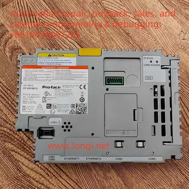
Module SP-5B10

1. Module Positioning: The Core Processing Unit of the HMI

The Pro-face SP-5B10 box module (also known as the “enhanced box module” or “Power Box”) is the “brain” of the SP5000 series touchscreen system. It houses the processor, memory, and various industrial communication interfaces. Unlike a traditional, single-unit HMI device, Pro-face introduced a modular approach in the SP series by separating the display section and the processing section, referred to as the display module and the box module, respectively. As the box module, SP-5B10 is in charge of running control logic, storing project data, connecting devices via different networks, and overseeing the overall operation of the system.

2. The “Brain” for Running Business Logic and Display Screens

In practical applications, an HMI often needs to run custom programs for production lines, equipment, or processes—such as displaying workflows, monitoring real-time data, and sending or receiving control commands. These configured screens and logic programs are developed via software like GP-Pro EX and are downloaded to the box module. The SP-5B10 provides ample processing power and memory to execute these screen logics, data collection tasks, and alarm management. It then transmits the resulting display data to the display module. Essentially, without the box module’s processing and control, the HMI’s “intelligence” does not exist, and the touchscreen would be reduced to a blank display panel.

3. Data and System Software Storage

The SP-5B10 box module integrates storage features, including an SD card slot, internal flash memory, and backup battery. In more detail:

  • System Storage: Contains the HMI’s system firmware, operating system, and basic drivers needed for startup.
  • Project Data Storage: Stores project files, alarm information, recipe data, etc., that are downloaded from development software such as GP-Pro EX. This approach allows easy maintenance; for instance, if the display module needs replacing, simply removing and reattaching the box module or swapping the storage card can restore the entire application.
  • Alarm and Historical Records: Many industrial environments require the recording of alarm data and operational logs—sometimes for weeks or months. The SP-5B10’s internal flash memory or SD card meets these demands.

4. The Central Hub for Multiple Industrial Communication Interfaces

In industrial settings, an HMI commonly exchanges data with PLCs, inverters, sensors, or upper-level management systems, making diverse interfaces and protocols critical. The SP-5B10 often includes:

  • Ethernet Ports: Typically at least one or two RJ-45 ports supporting 10/100/1000 Mbps to connect PLCs, SCADA, or MES systems.
  • Serial Interfaces (COM Ports): RS-232C, RS-422/485, etc., for older PLCs and instruments still widely used.
  • USB Host/Device Ports: For connecting USB peripherals such as flash drives or barcode scanners, as well as for direct communication or program downloads from a PC.
  • Expansion Bus: Some box modules allow additional interface cards (e.g., fieldbus expansions, field I/O boards) to suit a variety of automation scenarios.

As the conduit for all external signals and data, the SP-5B10 processes information before passing it on to the display module, allowing seamless “field–HMI–network” connectivity.


III. How the SP-5B10 Works with the Display Module

1. Physical Connection: A Rear Plug-in Connector

In the Pro-face SP5000 series, the box module and display module link up via a specialized connector on the display’s rear side. The box module securely latches onto the display module through a rail or clip mechanism:

  • Power Supply: The display module connects to external power (e.g., 24 V DC) and converts it internally to power the box module, which does not require its own power input.
  • Signal Transmission: The connector transmits video signals while also carrying touch input signals and other data between the processor and display.

This modular concept makes it easy for users to replace or upgrade components. For example, if you want to switch to a larger display but keep the same box module, simply remove the original display and connect the SP-5B10 to a new, larger SP series display. Likewise, if you need higher processing performance, you can upgrade only the box module without having to swap out the entire display screen.

2. Logical Coordination: Clear Division of Labor, Integrated Operation

The SP-5B10 handles core computing, communications, and data storage, while the display module is responsible for UI presentation and touch sensing. Their cooperation can be summarized as:

  • Screen Data Transmission: The SP-5B10 runs the screen logic and sends the display content to the display module, which then renders and displays it.
  • Touch Feedback: When an operator touches a button or drags an object on the screen, the display module detects the action and relays it back to the box module for processing, which either responds or carries out related control commands.
  • System Health Management: If the box module detects high temperature or an internal fault, it can alert the display module to show warnings or shut off the backlight, ensuring safe operation of the entire system.

IV. What Happens if You Remove the SP-5B10?

Many wonder whether the front display panel can still function if the box module is taken out. The short answer is no. The SP-5B10 is not a simple add-on accessory; it is the “brain” and “heart” of the entire HMI system. Once it is removed, the display module loses its processor, memory, and communication interfaces, which means it becomes non-functional. Specifically:

  1. No Display
    Without the display data provided by the SP-5B10, the screen may only have power for the backlight (if at all) but will show no graphics or text. All HMI screens are generated by the box module, so with it removed, there is no output signal for the display panel.
  2. No Touch Operation
    Since no box module is present to read and process touch coordinates, any touch input is rendered meaningless. Typically, the screen’s coordinate signals must be sent to and interpreted by higher-level software or the OS, which runs on the SP-5B10.
  3. Loss of Data Collection and Communication
    The box module provides interfaces like serial ports, Ethernet, and USB. Removing it also removes these interfaces, and thus the touchscreen can no longer communicate with PLCs, sensors, or PCs. Effectively, all monitoring and control functions cease.
  4. Loss of System and Project Data
    The SP-5B10 stores screen projects, recipes, alarm history, and more on an SD card or in internal memory. Removing the module effectively takes away all critical data needed for system operation. The display module itself usually does not retain these files and cannot independently load the application.

Hence, removing the SP-5B10 renders the Pro-face touchscreen incapable of displaying or interacting with any functionality. The system will only resume normal operation once the box module (or a compatible alternative) is reattached and powered up.


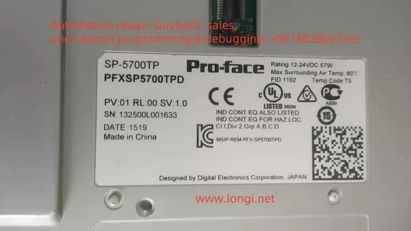
Display screen SP-5700TP

V. Conclusion and Recommendations

In summary, the Pro-face SP-5B10 box module is an irreplaceable core component of the SP series touchscreen. It not only handles screen display and touch input processing, but also provides the storage space, communication interfaces, and expansion capabilities vital for complete HMI functionality. For engineers and maintenance personnel who rely on Pro-face HMIs for field device monitoring, data collection, and process visualization, ensuring that the box module and display module remain properly connected and functioning is crucial.

If you need a functioning display, you cannot rely solely on the screen hardware. During maintenance, if you must remove the box module, always do so with the power off and take precautions to protect the storage card and the module from static or physical damage. Bear in mind that once the SP-5B10 is removed, the touchscreen loses its central processing capability and will not operate; only by reinstalling the compatible box module and powering the system can normal functions be restored.

In essence, the SP-5B10 module is like the processor and storage system in a smartphone—without it, even the best screen is just inert “glass.” Removing it inevitably leads to loss of the original interface, disabling any touch inputs or data communications. Therefore, to ensure stable, continuous operation of Pro-face HMIs, the SP-5B10 and display module must remain tightly integrated so that the system can take full advantage of the module’s high-speed processing and multi-interface communication features, enabling better equipment monitoring and process management on the industrial floor.


Posted on Leave a comment

A Detailed Application Plan of the Yuqiang YQ3000-G11 Inverter on a Film Blowing Machine

Below is a detailed application example based on the typical functional requirements of a film blowing machine, combined with the common wiring and parameter settings of the Yuqiang YQ3000-G11 inverter. Since a film blowing machine usually involves multiple drive lines (e.g., the main extruder motor, traction motor, winder motor, blower, etc.), this focuses on the control concepts, wiring diagrams, and parameter settings of the major sections for reference and subsequent adjustments.


I. Main Transmission Sections of the Film Blowing Machine and the Application Approach of the Inverter

  1. Main (Extruder) Motor
    • Function: Drives the screw to extrude the melt, controlling the basic output of the entire film blowing process.
    • Inverter requirements: Generally requires higher power, smooth start, and stable torque output. Vector control or torque control mode can be used for better low-speed torque and speed stability.
    • Key points: Usually requires an external speed reference (e.g., PLC/HMI for production or speed settings) or manual potentiometer for speed command.
  2. Traction Motor (sometimes called the stretching motor)
    • Function: Continuously pulls the film upward from the die head, determining the stretching ratio and helping ensure uniform thickness.
    • Inverter requirements: Medium power, accurate speed control, sometimes requiring multi-speed or tension control.
    • Key points: Needs to coordinate with the main extruder speed, maintaining a stable line speed. Usually has a speed ratio with the main extruder or uses a tension sensor/dancing roller position sensor for closed-loop control.
  3. Winding Motor
    • Function: Winds the formed film into rolls, potentially requiring constant tension or taper tension control.
    • Inverter requirements: Must maintain stable tension even under a wide speed range. Sometimes paired with sensors or a tension controller.
    • Key points: Depending on production line requirements, may adopt vector control with torque limit or rely on an external tension controller for speed regulation.
  4. Fan/Cooling Motor (e.g., air ring, cooling blower, etc.)
    • Function: Provides stable cooling airflow for the film blowing process.
    • Inverter requirements: Relatively medium or smaller power, typically just needs constant speed or simple speed control.
    • Key points: Often uses multi-speed or simple inverter-based speed variation to adjust airflow volume.

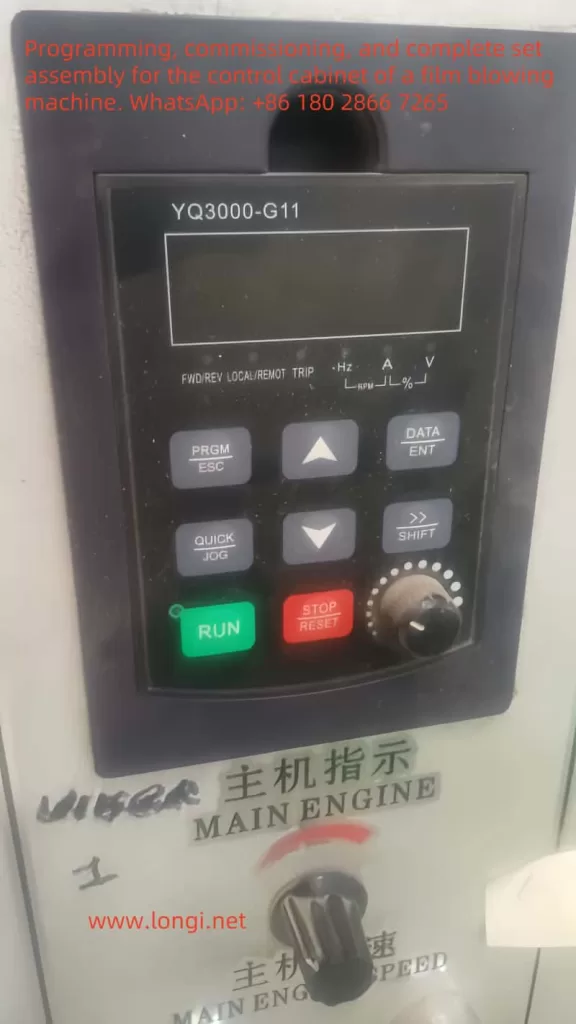
YQ3000-G11

II. Recommended Main Hardware and Control System

  1. Inverter
    • Model: Yuqiang YQ3000-G11 (select power ratings according to each motor, such as 7.5kW, 11kW, 15kW, 22kW, etc.).
    • Quantity: Depends on the number of motors that need control—commonly at least one each for the extruder, traction, and winding motors.
  2. PLC and HMI (Touch Screen)
    • Suggest using a small PLC (e.g., Siemens S7-1200, Mitsubishi FX5U, or domestic brands like Xinje, Delta, etc.), plus a 7”–10” touch screen.
    • Purpose: Centralized management of line speed reference, process parameters, tension or speed ratio control. The touch screen is used for operator interface, convenient speed adjustments, alarm displays, etc.
  3. Auxiliary Components
    • Potentiometer (if only manual speed control is needed and not controlled by a PLC).
    • Limit switches/proximity switches (to detect traction/tension roller positions).
    • Tension sensor/dancing roller position sensor (if tension control is required).
    • Common protection components such as contactors, circuit breakers, and thermal relays.
    • If an encoder is needed (closed-loop vector or synchronization), choose an inverter model with encoder interface and the corresponding encoder.

III. Major Inverter Wiring Examples

Below is a detailed explanation taking the “main extruder motor” as an example. The wiring logic for traction/winder motors is similar. For multiple inverters, each will have similar main circuit wiring but will differ in how the control terminals interface with the PLC’s I/O.

1. Main Circuit Wiring Diagram

3-phase AC power (R,S,T) -----
                      |----- [Circuit breaker] -----|
                      |                             |
                      |---- [AC contactor (optional)] --|---- L1, L2, L3 ---> Inverter(YQ3000-G11) input
                      |                                                  

                      |----> Inverter(YQ3000-G11) output U, V, W ---> Main motor U, V, W

                      [PE] --------------------------> Inverter PE ----> Motor chassis ground

Note:

  • For larger motors, it is advisable to add a contactor or soft starter on the input side of the inverter for protection or maintenance.
  • Do not place contactors or switches between the inverter output and the motor, as this could lead to overcurrent or inverter damage.
  • Proper grounding is mandatory for safety and to reduce electromagnetic interference.

2. Control Circuit (Low-Voltage Signals) Wiring Example

Below is a scenario where the PLC provides the run command and analog speed reference. If only one inverter is needed and you want manual speed control, you can connect a potentiometer to the AI terminal.

  PLC digital output Y0  ----------------> Inverter DI1 (Forward run) 
  PLC digital output Y1  ----------------> Inverter DI2 (Reverse / other user-defined function)
  PLC digital output Y2  ----------------> Inverter DI3 (multi-step speed1 / e-stop reset / etc.)
  ...
  
  PLC common COM       ------------------> Inverter DCM (digital common)

  PLC analog output AO0(0-10V)  -------> Inverter AI1 (analog speed reference)
  PLC analog ground AGND         -----> Inverter GND (analog reference ground)

  Inverter relay output(FA/FB/FC) -----> PLC digital input X0/X1 (for fault alarm/running signal)
  Inverter DO(OC/OD) -------------> PLC digital input X2 (additional programmable output if needed)

Note:

  • Typical naming for digital inputs is DI1, DI2, DI3…, with DCM as the common terminal; AIx are analog inputs, and GND is for analog reference; FA/FB/FC are relay outputs; OC/OD are open-collector outputs.
  • You can assign various functions (e.g. multi-step speeds, jog mode, fault reset, emergency stop, etc.) to the DI terminals according to production line demands.
  • If not using a PLC, a simple method is to set the inverter’s run command source to “panel/terminal” on the unit and connect a potentiometer (10kΩ–20kΩ) to AI1 to provide a manual speed reference.

IV. Key Function Parameter Settings

Below are typical function parameters of Yuqiang YQ3000-G11 inverters. Refer to the official manual for accuracy, as parameter numbers and names may vary by version. Common key parameters include:

  1. Control Method Selection
    • For example: P00.0 = 2 means vector control (without PG); P00.0 = 0 means V/F control. Choose based on motor characteristics and load requirements.
    • For closed-loop vector (with encoder), select a model supporting a PG card and set P00.0 to the corresponding mode (e.g., 3 or 4).
  2. Run Command Source
    • For example: P00.1 = 1 for terminal run commands; P00.1 = 2 for communication (RS485/Modbus) run commands; P00.1 = 0 for operation panel commands.
    • If the PLC’s digital outputs handle start/stop, set it to “terminal run command.”
  3. Frequency Reference Source
    • For example: P00.2 = 1 for AI1 analog input; P00.2 = 2 for multi-step speed; P00.2 = 3 for communication reference; P00.2 = 0 for operation panel reference.
    • If the PLC’s analog output (0–10V) is used for speed reference, choose AI1.
  4. Motor Parameter Settings (very important)
    • Set motor rated power, current, voltage, frequency, and speed. For vector control, these must be accurate.
    • E.g., P01.0 ~ P01.4 may correspond to rated voltage, rated current, rated power, rated frequency, rated speed (details depend on the manual).
  5. Acceleration/Deceleration Times
    • For example: P00.3 (accel time), P00.4 (decel time). Adjust based on process needs. For large-inertia extruders, slightly lengthen accel/decel to prevent shock.
  6. Maximum Frequency / Base Frequency
    • For example: P00.5 (max frequency), P00.6 (upper frequency limit), P00.7 (base frequency). Typically set to 50Hz or 60Hz, but can be increased if needed for the process.
  7. Multi-Step Speeds / Simple Tension Control
    • If multi-step speeds are required, configure the corresponding parameters (e.g., P10.x ~ P11.x) and digital terminals.
    • For constant tension control, use vector mode with torque limiting or external PID (internal to the inverter or from the PLC).
  8. Fault Protection and Monitoring
    • Set protection parameters such as overcurrent, overload, overvoltage, and choose how to reset faults (automatic or via terminal).
    • Configure the inverter’s relay outputs for fault or running signals to feed back to the PLC.

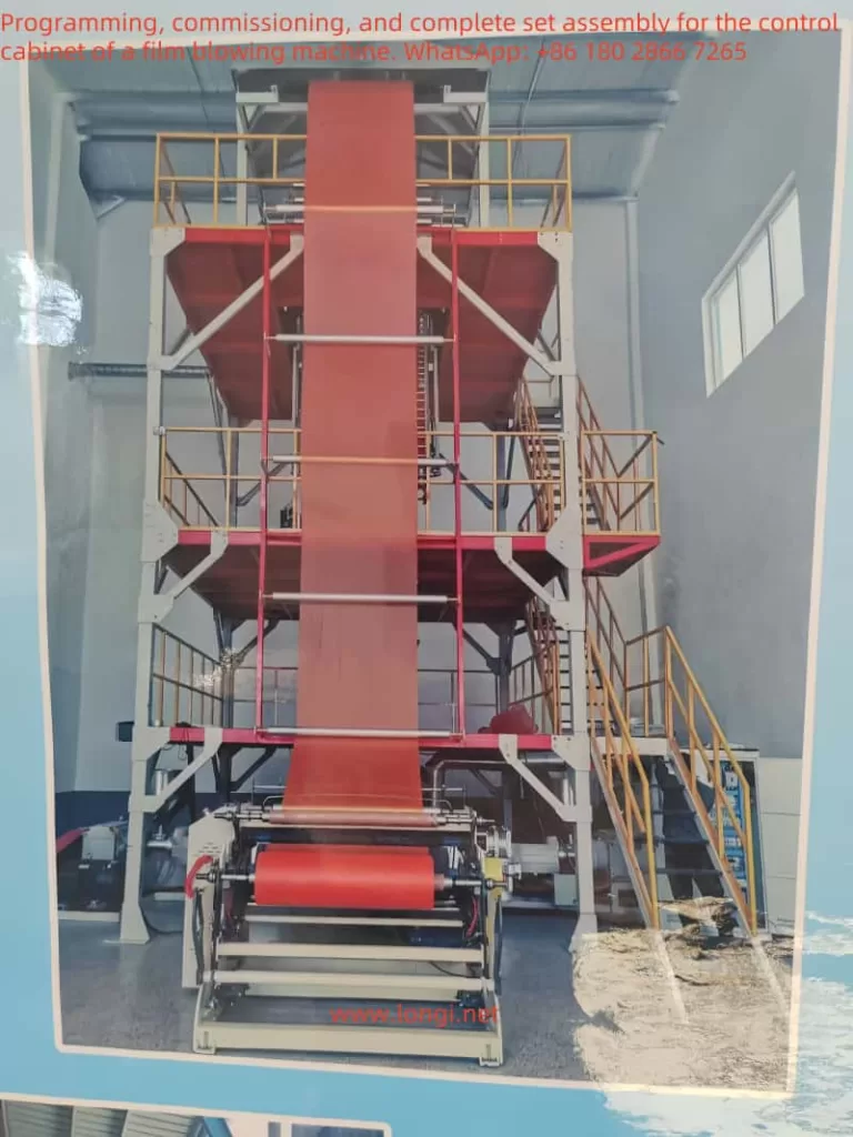
film blowing machine

V. Example of Specific Functional Implementation

  1. Extruder Motor Speed Control
    • Hardware Link: PLC HMI -> PLC AO -> AI1 (inverter) -> inverter output -> motor
    • Process:
      1. Operator sets the desired extruder screw speed/throughput on the HMI (corresponding to 0–10V or 4–20mA). The PLC sends this analog signal to AI1 on the inverter.
      2. The PLC also outputs a digital run command (RUN) to DI1 on the inverter, starting it.
      3. The inverter, using vector or V/F control, drives the extruder motor at the specified speed.
      4. If a fault occurs, the inverter’s relay feedback signals the PLC, and the HMI displays an alarm.
  2. Traction Motor Constant Line Speed Control
    • If precise tension control is not needed, maintain a fixed ratio between traction speed and main extruder speed. The PLC calculates a proportional command from the extruder speed/frequency and outputs it to the traction inverter.
    • For tension or speed tracking, use a tension sensor/dancing roller with a PID loop:
      1. The sensor provides a 4–20mA feedback to the PLC analog input, where a PID algorithm is carried out.
      2. The PLC analog output then drives AI1 on the traction inverter.
      3. Tuning the PID parameters keeps tension or roller position stable.
  3. Winding Motor Tension Control (Optional)
    • A simple method is taper tension control, where torque or speed decreases as the roll diameter increases. Alternatively, use an external tension controller with the inverter.
    • If the inverter has a built-in PID, the tension sensor signal can be fed into AI2, and the inverter automatically adjusts the output frequency to maintain tension. Or the PLC can handle the loop and send a command to the inverter.
    • It is essential to coordinate with the traction speed to prevent slack or overstretching.

VI. Text-Based Wiring and Control Diagram (Simplified Example)

Below is a rough diagram using dashes, omitting some components and multiple motors. It highlights the main structure:

================= Three-Phase Power =================
|        R          S          T                    |
|        |          |          |                    |
|      [Breaker]  [Contactor]  ...                  |
|        |          |                               |
|        \-------- Inverter (L1,L2,L3) -------------/
|                 |
|                 |--- U --- Main motor U
|                 |--- V --- Main motor V
|                 \---W --- Main motor W
|                                
|---- [PE] ------ Inverter PE --- Motor chassis ground
|
|============= PLC (Digital/Analog IO) & HMI ============
       |         PLC: Y0 --------------> DI1 (Inverter)
       |         PLC: Y1 --------------> DI2 (Inverter)
       |         PLC: COM -------------> DCM (Inverter)
       |
       |         PLC: AO0(0-10V) ------> AI1 (Inverter)
       |         PLC: AGND -----------> GND (Inverter)
       |
       |<< Inverter FA/FB/FC (Fault/Run) >> PLC X0 etc.
       |
       |----- HMI (Comm port) <----> PLC (Comm port)
       |
=========================================================

To control traction, winding, and fan motors with separate inverters, replicate the main circuit connection (each with its own three-phase power supply and protective devices). The control circuit can be expanded by assigning more digital outputs and analog outputs in the PLC, or using RS485 communication to reduce the number of analog channels.


VII. Usage and Commissioning Recommendations

  1. Pre-Startup Check
    • Verify the power supply voltage, wiring terminals, and grounding are correct.
    • Use a multimeter to check the voltage/resistance of AI1, DI1, etc., to ensure they match the design.
    • Ensure motor parameters are correctly set in the inverter.
  2. Initial No-Load Test Run
    • Disconnect the motor from the load or run at low speed with no load. Observe current and voltage, and confirm correct rotation direction.
    • Test emergency stop, fault protection, and reset functions.
  3. Load Test Run
    • Gradually apply load from a low speed, watching for overcurrent or temperature issues.
    • Observe the process effect (e.g., film thickness uniformity, tension stability) and adjust acceleration/deceleration time or PID parameters if necessary.
  4. Parameter Optimization
    • If speed instability or tension fluctuation occurs, refine vector control gains, torque compensation, or PID settings as recommended by the manual.
    • Optimize the PLC program for traction and winding speed/tension coordination.
  5. Fault and Protection
    • Set appropriate fault levels (whether the drive stops immediately on alarm, etc.) and any delay features to avoid inadvertent stoppage or delayed protection.
    • Regularly check the cooling path, filter, and fans for proper operation.

VIII. Conclusion

By using multiple Yuqiang YQ3000-G11 inverters, one can separately drive the main extruder, traction, and winding motors of a film blowing machine, thus realizing automated control over production rate (speed), film thickness (speed ratio), and tension (winding).
For wiring, the main circuit employs a three-phase input and U/V/W outputs to the motor. The control circuit can flexibly employ PLC/HMI digital and analog signals for start/stop and speed references.
When configuring parameters, accurately input the motor’s rated data and set reasonable acceleration/deceleration times, maximum frequency, torque boost, tension control, and multi-step speeds.
In more complex setups involving tension control, dancing roller control, or multi-segment process curves, further development can be done using the inverter’s built-in functions or PLC logic for greater flexibility and parameter optimization.

Posted on Leave a comment

In-depth Analysis and Solutions for ABB Inverter ACS580 Series Fault 7086


Introduction

In the field of industrial automation, ABB’s ACS580 series inverter is widely used in various drive control scenarios due to its high efficiency and stable performance. However, during actual operation, the inverter may encounter faults for various reasons, among which FAULT 7086 is a relatively typical issue. This article will systematically analyze the handling strategies for this fault from the aspects of fault definition, causes, solutions, and preventive measures, providing comprehensive guidance for equipment maintenance personnel.

I. Fault Definition and Background Analysis

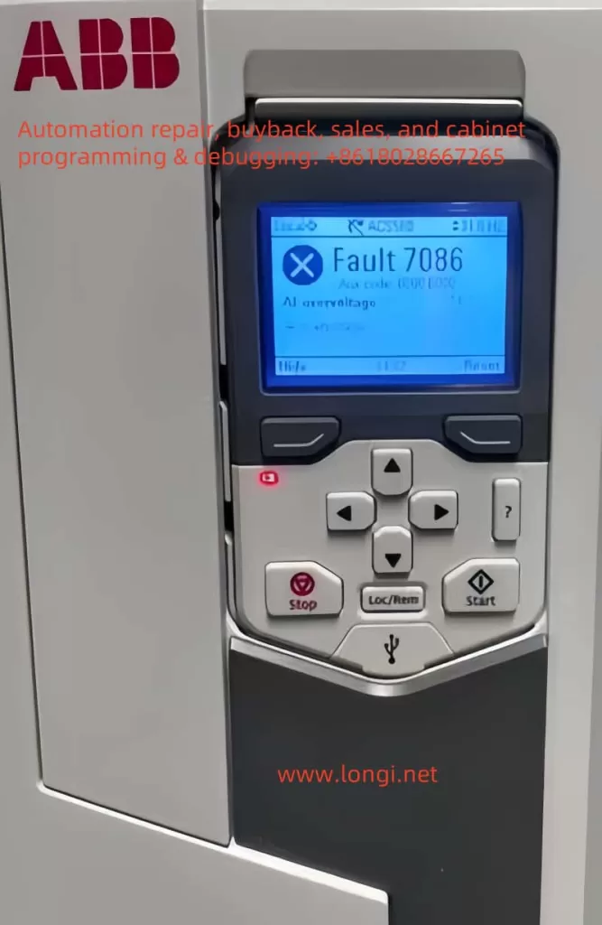
FAULT 7086 is officially defined as Analog Input Overvoltage (AI Overvoltage), which means the inverter detects that the voltage of the analog input (AI) signal exceeds the preset threshold. When this fault is triggered, the inverter will automatically switch the AI input mode from current mode to voltage mode to protect the circuit. After the signal returns to normal, the system can switch back manually or automatically.

From a design logic perspective, the AI input is a crucial interface for the inverter to receive external control signals (such as sensor data and setpoints). Its stability directly affects the control accuracy and system safety. When the input voltage rises abnormally, it may damage the internal circuit or cause control logic errors. Therefore, the inverter needs to issue an early warning through a fault code.

Fault 7086

II. In-depth Analysis of Fault Causes

2.1 AI Signal Source Issues

  • Sensor Failure: Sensors for temperature, pressure, etc., may output abnormally high voltages due to aging or damage.
  • Signal Source Configuration Errors: For example, connecting a 0-10V output device to a 4-20mA input terminal, resulting in signal level mismatch.

2.2 Wiring and Interference Issues

  • Short Circuit in Wiring: Short circuits in AI signal lines or damage to connectors.
  • Electromagnetic Interference (EMI): Parallel routing of AI signal lines with high-power lines (such as motor cables and inverter output lines) without shielding measures.

2.3 External Device Failures

  • PLC or Controller Anomalies: Control devices may output error signals due to program errors or hardware failures.
  • Power Fluctuations: Unstable power supply to external devices, leading to signal level fluctuations.

2.4 Drive Internal Failures

  • AI Processing Circuit Damage: Aging components, lightning strikes, or operational errors causing circuit failure.
  • Firmware Version Defects: Old firmware versions may have vulnerabilities in AI input detection algorithms.

III. Fault Impact and Risk Assessment

3.1 Direct Impact on the Control System

  • Reduced Control Accuracy: AI input anomalies may cause deviations in setpoints such as speed and torque.
  • System Shutdown: If the fault is not cleared in time, the inverter may trigger protective shutdown.

3.2 Potential Risk Analysis

  • Equipment Damage: Prolonged overvoltage may burn out the AI input module or main control board.
  • Production Loss: Sudden shutdowns or control anomalies may halt production lines, resulting in economic losses.

IV. Systematic Solutions

4.1 Preliminary Diagnostic Process

  1. Observe the Control Panel: Confirm whether fault code 7086 is accompanied by a red warning light.
  2. Record Ax Code: If Ax code (00 000) is displayed, locate the specific channel with the manual.

4.2 Step-by-step Handling Strategies

4.2.1 Signal Source Inspection

  • Calibration Verification: Use a standard signal source to test the AI input channel and confirm detection accuracy.
  • Replacement Method for Troubleshooting: Temporarily replace sensors or signal lines to observe whether the fault transfers.

4.2.2 Wiring Optimization

  • Physical Isolation: Separate AI signal lines from high-power lines and add metal shielding.
  • Grounding Inspection: Ensure common grounding of the signal source, inverter, and control cabinet to reduce potential differences.

4.2.3 External Device Diagnostics

  • Signal Isolation: Add signal isolators between the PLC and inverter to block interference transmission.
  • Power Purification: Equip external devices with UPS or APF devices to eliminate power harmonics.

4.2.4 Drive System Handling

  • Firmware Upgrade: Update to the latest firmware version through Drive Composer tools.
  • Parameter Reset: Restore AI input parameters to factory settings and reconfigure them step-by-step.

4.3 Advanced Handling Techniques

  • Waveform Analysis: Use an oscilloscope to capture AI signal waveforms and identify transient interference or continuous overvoltage.
  • Temperature Monitoring: Check the internal temperature of the inverter to rule out circuit false alarms caused by overheating.

V. Preventive Maintenance Strategies

5.1 Regular Inspection Plan

  • Quarterly Inspections: Measure AI signal levels and verify sensor accuracy.
  • Annual Maintenance: Clean the inside of the control cabinet and inspect wiring aging.

5.2 Parameter Management Practices

  • Backup Configuration: Before modifying AI parameters, use Drive Composer to export the configuration file.
  • Version Control: Establish a firmware version ledger to track upgrade records.

5.3 Personnel Training Mechanisms

  • Skill Certification: Require maintenance personnel to pass ABB official training and master fault handling procedures.
  • Case Sharing: Establish a fault handling database and regularly analyze typical cases.

VI. Conclusion

Although FAULT 7086 involves multiple potential causes, the occurrence probability can be significantly reduced through systematic diagnostic procedures and preventive maintenance strategies. During actual handling, maintenance personnel should prioritize troubleshooting signal sources and wiring issues, utilizing oscilloscopes and other tools for in-depth analysis. Meanwhile, it is recommended that enterprises establish equipment health records and achieve predictive maintenance through data-driven approaches, thereby comprehensively enhancing the operational reliability of ACS580 series inverters. For complex faults, promptly contacting ABB technical support and leveraging the manufacturer’s professional resources can significantly shorten fault recovery time.

Posted on Leave a comment

User Guide for Hyundai Inverter N700E Series Manual

I. Operation Panel Functions and Key Settings

(I) Introduction to Operation Panel Functions

The operation panel of the Hyundai Inverter N700E Series is an important interface for user interaction with the inverter, mainly used for setting inverter parameters, monitoring operating status, and executing control commands. The operation panel is usually equipped with a display screen, which can display key parameters such as the operating frequency, current, and voltage of the inverter in real time; a run key for starting the inverter; a stop/reset key for stopping the inverter or resetting faults; and a frequency setting knob that allows users to manually adjust the output frequency of the inverter.

(II) Restoring Factory Default Settings

To restore the inverter parameters to factory settings, follow these steps:

  1. Enter the extended function mode (Group b parameters).
  2. Select the initialization mode (parameter b12).
  3. Set parameter b12 to “1”. The inverter will then clear the fault history and restore factory settings.

(III) Copying Parameters to Another Inverter

Although the manual does not directly mention the specific copying method, modern inverters generally support parameter copying through communication interfaces (such as RS485). The general steps are as follows:

  1. Connect the inverter to a computer using a dedicated communication cable.
  2. Use the software tool provided by the inverter manufacturer to upload the parameters of the source inverter to the computer.
  3. Download the saved parameters from the computer to the target inverter.

(IV) Setting Passwords and Access Restrictions

To protect the inverter settings from being changed arbitrarily, passwords and access restrictions can be set. For example, using the software lock function (parameter b09) can lock all parameters except the output frequency. Refer to the detailed steps in the manual for specific setting methods, which usually include entering the password setting mode, entering a new password, and selecting the parameters to be locked.

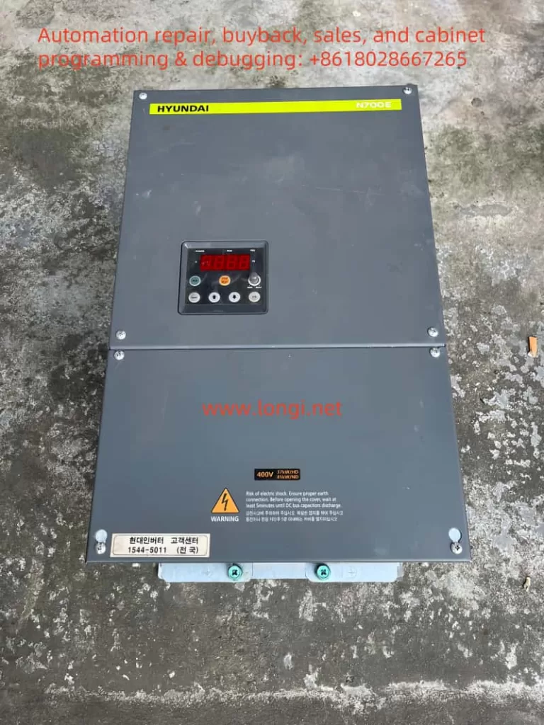
hyundai inverter N700E

II. External Terminal Control and Speed Regulation Implementation

(I) Forward and Reverse Control via External Terminals

  1. Wiring Terminals: Use the FW (forward operation) and RV (reverse operation) terminals.
  2. Setting Parameters:
    • Set parameter A02 (operation command selection) to “1” to select external terminal control mode.
    • Ensure that parameter C01 (smart input terminal 1 setting) is set to “0” for forward operation and parameter C02 (smart input terminal 2 setting) is set to “1” for reverse operation.
  3. Control Circuit Wiring Diagram:复制代码[FW] ----[Switch]----[CM1][RV] ----[Switch]----[CM1]When the switch between the [FW] terminal and the common terminal CM1 is closed, the inverter operates in the forward direction; when the switch between the [RV] terminal and the common terminal CM1 is closed, the inverter operates in the reverse direction.

(II) Speed Regulation via External Potentiometer

  1. Wiring Terminals: Connect an external potentiometer to the O (voltage input) and L (common) terminals.
  2. Setting Parameters:
    • Set parameter A01 (frequency command selection) to “1” to select external voltage/current input mode.
    • Ensure that the potentiometer is correctly connected to the O and L terminals. Rotate the potentiometer to adjust the output voltage and control the output frequency of the inverter.
  3. Control Circuit Wiring Diagram:复制代码Potentiometer ----[O]----[Inverter] |\n [L]----[GND]

III. Inverter Fault Codes and Solutions

(I) Fault Codes and Their Meanings

Fault CodeFault NameMeaning
E04Overcurrent ProtectionTriggered when the inverter output current exceeds approximately 200% of the rated current
E05Overload Protection (Electronic Thermal Relay)Triggered when the motor is overloaded
E07Overvoltage ProtectionTriggered when the DC bus voltage exceeds the specified value
E09Undervoltage ProtectionTriggered when the input voltage is below the specified value
E12External FaultTriggered when the inverter receives a corresponding signal from an external device or unit that has malfunctioned
E13Unattended Start ErrorTriggered when the inverter is already in operation upon power-on
E17Inverter OverloadTriggered when the power device IGBT overheats
E20Input Phase LossTriggered when an input AC power phase loss is detected
E21Temperature TripTriggered when the main circuit temperature rises due to the cooling fan stopping
E22Safety Function FaultTriggered when the safety input signal is active

(II) Fault Solutions

  1. E04/E17 (Overcurrent Protection/Inverter Overload):
    • Check if the motor and load are too large, reduce the load or replace with a larger capacity inverter.
    • Check for short circuits or ground faults in the motor windings.
  2. E05 (Overload Protection):
    • Check if the motor is overloaded, reduce the load or adjust the protection level of the electronic thermal relay (through relevant parameter settings).
    • Check the motor cooling condition and ensure good motor ventilation.
  3. E07/E09 (Overvoltage Protection/Undervoltage Protection):
    • Check if the input power is stable and ensure the voltage is within the specified range.
    • If the power is unstable, consider installing a voltage stabilizer.
  4. E12 (External Fault):
    • Check external devices or units, troubleshoot and reset the inverter.
  5. E13 (Unattended Start Error):
    • Ensure that the inverter is not in operation before powering on.
  6. E20 (Input Phase Loss):
    • Check for input power phase loss and ensure normal three-phase power supply.
  7. E21 (Temperature Trip):
    • Check if the cooling fan is working properly and ensure good heat dissipation of the inverter.
    • Clean the dust and debris inside the inverter to improve heat dissipation conditions.
  8. E22 (Safety Function Fault):
    • Check the safety input signal circuit and ensure normal safety function.

For all fault codes, first check the error code on the inverter’s display screen or operation panel, and then troubleshoot and resolve them step by step according to the fault troubleshooting procedures in the manual. If the problem persists, contact professional maintenance personnel or the technical support department of the inverter manufacturer in a timely manner to avoid more serious consequences.

Posted on Leave a comment

AMDO Inverter VCD-2000 Series User Manual Usage Guide

I. Introduction to the Operation Panel Functions

1.1 Operation Panel Layout

The AMDO Inverter VCD-2000 series’ operation panel is designed to be concise and straightforward, primarily consisting of the following components:

  • Digital Display: Shows the inverter’s operating status, set frequency, output frequency, and other parameters.
  • Function Keys: Includes Run, Stop/Reset, Function/Data, Jog/Reverse, Increase, Decrease, Shift/Monitor, and Store/Switch keys.
  • Analog Potentiometer: Used for manually adjusting the output frequency.
  • Indicator Lights: Includes Forward (FWD) indicator, Reverse (REV) indicator, and Alarm (ALM) indicator, which indicate the inverter’s operating status.
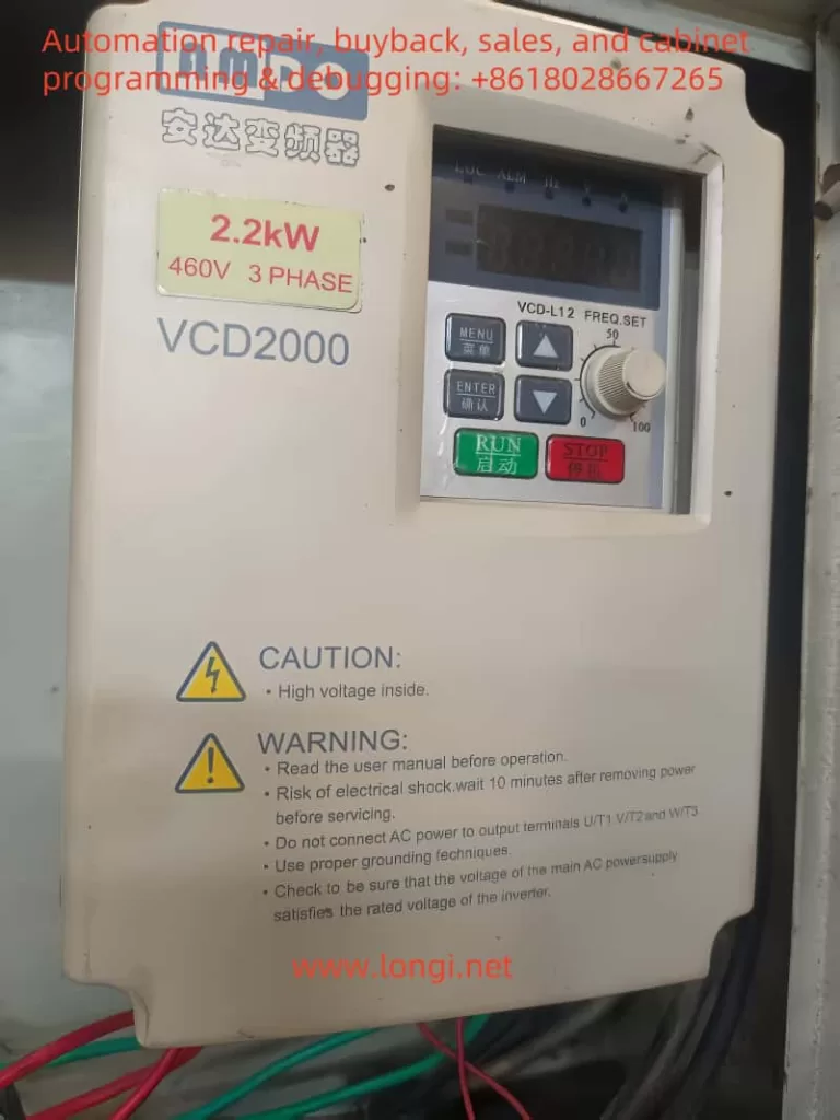
VCD2000

1.2 Restoring Parameters to Factory Defaults

Restoring parameters to factory defaults is an important operation that can be completed through the following steps:

  1. Press the Function/Data key to enter the programming mode.
  2. Use the Increase and Decrease keys to select parameter P3.01.
  3. Press the Shift/Monitor key to enter the parameter modification mode.
  4. Set the value of P3.01 to 10 (Restore Factory Defaults).
  5. Press the Store/Switch key to save the settings and exit the programming mode.

1.3 Setting and Removing Passwords

To prevent unauthorized modifications, the inverter supports password protection. The steps for setting and removing passwords are as follows:

  • Setting a Password: Enter parameter P9.14, input a four-digit password, and press the Store/Switch key to save it.
  • Removing a Password: Enter parameter P9.14 and set the parameter value to 0000 to disable password protection.

1.4 Copying Parameters to Another Inverter

Parameters can be copied between inverters using a remote keyboard. The specific steps are as follows:

  1. Connect the remote keyboard to the source inverter.
  2. Enter the parameter copying function (parameter P3.02) and select parameter upload.
  3. Connect the remote keyboard to the target inverter.
  4. Enter the parameter copying function and select parameter download.

II. External Terminal Control

2.1 External Terminal Forward and Reverse Control

Forward and reverse control can be achieved through external terminals by setting appropriate parameters and correctly wiring. The specific steps are as follows:

2.1.1 Parameter Settings

  1. Enter parameter P0.03 and set it to 1 (Terminal Run Command Channel).
  2. Enter parameter P4.08 and select the appropriate operation mode (e.g., two-wire or three-wire control).

2.1.2 Wiring Instructions

  • Forward Control: Connect one end of the external forward button to terminal FWD and the other end to common terminal COM.
  • Reverse Control: Connect one end of the external reverse button to terminal REV and the other end to common terminal COM.

2.1.3 Standard Wiring Diagram

复制代码+-------+         +-------+| FWD   |---------| COM   |+-------+         +-------+       |+-------+         +-------+| REV   |---------| COM   |+-------+         +-------+

2.2 External Potentiometer Speed Adjustment

Speed adjustment can be achieved through an external potentiometer by setting appropriate parameters and correctly wiring. The specific steps are as follows:

2.2.1 Parameter Settings

  1. Enter parameter P0.01 and set it to 5 (VI Analog Given).
  2. Enter parameter P1.01 and set the gain of the VI channel (e.g., 1.00).

2.2.2 Wiring Instructions

  • One end of the potentiometer is connected to terminal VI.
  • The other end of the potentiometer is connected to common terminal GND.
  • The sliding end of the potentiometer is connected to terminal +10V.

2.2.3 Standard Wiring Diagram

复制代码+---------+         +-------+|    +10V |---------| VI    |+---------+         +-------+       |               |       |               |+---------+         +-------+| Potentiometer |---------| GND   |+---------+         +-------+

III. Fault Codes and Solutions

3.1 List of Fault Codes and Their Meanings

  • E-01: Overcurrent during acceleration, possible causes include heavy load, too short acceleration time, etc.
  • E-02: Overcurrent during deceleration, possible causes include too short deceleration time, potential energy load, etc.
  • E-03: Overcurrent during constant speed operation, possible causes include sudden load changes, too short acceleration/deceleration time, etc.
  • E-04: Overvoltage during acceleration, possible causes include abnormal input voltage, too short acceleration time, etc.
  • E-05: Overvoltage during deceleration, possible causes include too short deceleration time, potential energy load, etc.
  • E-06: Overvoltage during constant speed operation, possible causes include abnormal input voltage, too short acceleration/deceleration time, etc.
  • E-07: Overvoltage on the control power supply, possible cause includes abnormal input voltage.
  • E-08: Overheating, possible causes include blocked air ducts, high ambient temperature, etc.
  • E-09: Overload, possible causes include too short acceleration time, excessive load, etc.
  • E-10: Motor overload, possible causes include inappropriate V/F curve, low grid voltage, etc.

3.2 Fault Solutions

  • E-01 to E-06: Check the load conditions, appropriately extend the acceleration/deceleration time, adjust the V/F curve settings, and check if the input power supply is stable.
  • E-07: Check the input power supply to ensure stable voltage. If there are issues, seek service.
  • E-08: Clean the air ducts, improve ventilation conditions, reduce the carrier frequency, and replace the fan.
  • E-09 to E-10: Check the load conditions, appropriately extend the acceleration/deceleration time, adjust the V/F curve and torque boost settings, and select a more powerful inverter.

For all faults, the cause must be thoroughly investigated and resolved before resetting, as failure to do so may result in permanent damage to the inverter. If the issue cannot be resolved independently, contact after-sales service or professional repair personnel promptly.

IV. Conclusion

This article provides a comprehensive usage guide for the AMDO Inverter VCD-2000 series by introducing the operation panel functions, external terminal control, fault codes, and solutions. Users should strictly follow the instructions in the manual during operation to ensure the normal functioning of the inverter. Regular maintenance and upkeep are also crucial for extending the inverter’s service life.

Posted on Leave a comment

Application of the VCD-2000 Inverter in Circular Looms: A Detailed Design and Implementation Plan


I. Typical Motors Requiring Control in Circular Looms and the Approach to Using the Inverter

In a circular loom, there are generally several main motors to consider:

  1. Main Weaving Motor (Main Motor)
    • Used to drive the main shaft of the circular loom, weaving tubular fabric.
    • This motor often requires relatively precise speed regulation to match the requirements of yarn density, tension, etc.
    • It is recommended to use a vector-controlled inverter (i.e., VCD-2000 series full vector control) and perform motor parameter auto-tuning (dynamic or static) to ensure good low-speed torque output and speed accuracy.
  2. Winding/Pulling Motor
    • Winds the woven fabric onto the take-up roller or provides a stable pulling force.
    • This motor also usually requires adjustable speed capability to maintain a stable pull speed under different diameter/tension conditions.
    • If constant tension is required, consider using the inverter’s built-in PID regulation function (function group P7) by detecting the tension sensor feedback signal to adjust speed automatically.
  3. Warp Feeding or Auxiliary Motor
    • Used for feeding warp yarn, adjusting the yarn creel, or driving other auxiliary mechanisms. If it only requires simple speed changes or two to three speed stages, you can use the multi-speed function of the inverter (P3.26–P3.32) or simple external terminal switching.

Note: Whether each motor on the circular loom should be equipped with its own inverter depends on the production line requirements. This example focuses on a typical dual-inverter control plan for a “main weaving motor + winding motor.” If the equipment structure is simpler, you can equip only the main weaving motor with an inverter.


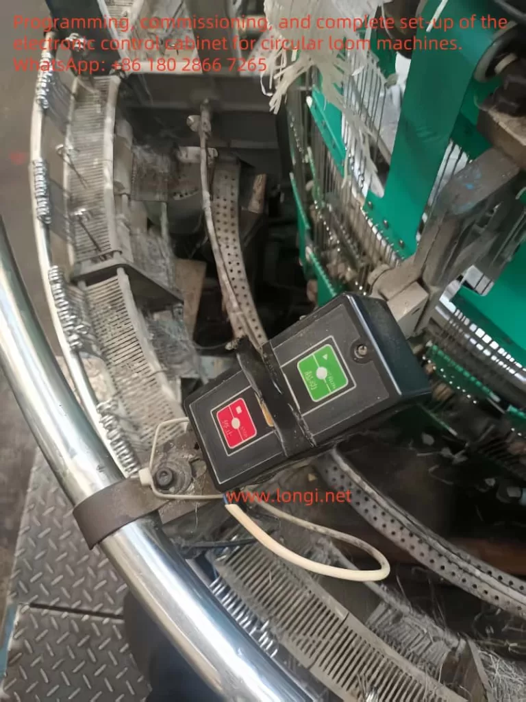
During the operation of the circular loom

II. Hardware Wiring

The wiring approach and terminal names/functions mentioned below are based on standard designations in the VCD-2000 series inverter manual. If your model’s terminal labels differ slightly, please refer to the actual nameplate and manual.

1. Main Circuit (Power Supply) Wiring

  • Connect the three-phase AC380V (or AC220V, depending on the model) power supply to the inverter input terminals R, S, T.
    • If it is a single-phase model, connect only two wires (R, T) for single-phase 220V.
  • The three output wires of the motor connect to the inverter output terminals U, V, W (ensure they match the U, V, W in the motor junction box; if the running direction is opposite the desired direction, swap any two motor leads or use the reverse command).
  • PE terminal (ground): Ensure both the inverter and motor have reliable grounding, typically via a dedicated ground wire directly connected to the cabinet ground bus or welded to the plant protective ground.
  • If a braking resistor is needed (for quick stopping or significant regenerative energy), connect one side of the resistor to the inverter terminal P+ (labeled “+” or “P”) and the other side to B (labeled “PB” or “DB”), and set the relevant braking parameters in the function codes (e.g., P2.05, P2.06, etc.).

2. Control Terminal Wiring — Example for Main Weaving Motor

Below is an ASCII-style diagram of a common “external terminal start/stop + analog potentiometer speed control + fault output” wiring configuration. If multi-speed, forward/reverse, PID regulation, etc. are required, you can adjust and expand upon this basic framework.

  ┌───────────────────────── VCD-2000 Inverter ──────────────────────────┐
  │   Main Circuit:                          Control Terminals (CN2 etc.)│
  │  ┌───────────┐                                                      │
  │  │ R  S  T    │<--- 3-phase AC input (AC380V)                        │
  │  │            │                                                      │
  │  │ U  V  W    │---> Connect to Main Weaving Motor (M1)               │
  │  │            │                                                      │
  │  │ P+   B     │---> Braking resistor here if needed                  │
  │  │ PE (Ground)│---> Ground                                           │
  │  └───────────┘                                                      │
  │                                                                     │
  │  Control Terminals Example:                                         │
  │    +24V ---[X1]---┐  (Example: X1 as forward FWD start command)      │
  │                   ├---> COM                                          │
  │    +24V ---[X2]---┘  (Example: X2 as reset or jog, depending on need)│
  │                                                                     │
  │  (Speed Set via Potentiometer)                                      │
  │     10V ---[Pot]--- VI                                             │
  │                 Other end of Pot --- GND                             │
  │                                                                     │
  │  (Fault Relay Output)                                               │
  │     TA ---  Relay NO Contact  --- TB                                 │
  │           Connect to external alarm circuit or indicator;           │
  │           TA-TB closing indicates inverter fault, etc.              │
  │           Refer to P4.11 or similar for multi-function output setup  │
  │  COM (Digital Common) and GND (Analog Ground) are separate, each    │
  │  single-point grounded nearby.                                       │
  └──────────────────────────────────────────────────────────────────────┘
  • Terminals X1–X6 can be assigned various functions in function codes P4.00–P4.07. In this example, X1 is set to “Forward Run” (FWD), and X2 can be set to “Reset/Stop” or “Jog,” etc.
  • If you need both forward and reverse, assign X1 = FWD and X2 = REV.
  • If you want to switch between panel (or PLC) control and external terminals, you can use multi-function terminals to implement “command channel switching” and “frequency channel switching” (assign codes 23, 24, etc. to P4.00–P4.07).
  • If you need PID tension control, connect the tension sensor (4–20mA or 0–10V) to CI or VI, then configure the relevant PID parameters in P7.00–P7.33.

3. Winding/Pulling Motor Inverter Wiring

  • The wiring principle is the same as for the main weaving motor. For constant tension winding, connect a tension sensor or pressure sensor output (4–20mA) to the inverter’s CI (or VI), and enable the PID function (P7.00=1).
  • Usually, you need to set P7.01=0 (digital setpoint) or 1 (analog setpoint) and P7.02=0 (VI feedback) or 1 (CI feedback) accordingly. Then configure P7.05 to match the feedback reading for the desired tension.

III. Core Function Codes and Parameter Examples

Below are key configuration ideas to help you understand typical debugging requirements for circular loom applications. In actual production, adjust them according to the motor nameplate, process needs, and auto-tuning results.

1. Basic Motor Parameter Auto-Tuning (Group PA)

  • PA.01: Motor Rated Power (kW)
    For example, 5.5 kW → set 5.5
  • PA.02: Motor Rated Voltage (V)
    For a 380V motor → set 380
  • PA.03: Motor Rated Current (A)
    According to the nameplate, e.g., 11.3A
  • PA.04: Motor Rated Frequency (Hz)
    Typically 50Hz
  • PA.05: Motor Rated Speed (rpm)
    For example, 1420 rpm
  • PA.06: Motor Poles
    For a 4-pole motor → set 4
  • PA.00: Auto-Tuning Mode
    • 1 = Dynamic auto-tuning (if the motor can be unloaded); press RUN to start.
    • 2 = Static auto-tuning (if it cannot be unloaded).
    After auto-tuning, you get better low-speed torque and stable speed performance.

2. Basic Operation Parameters (Group P0)

  • P0.00: Run Command Channel
    • 0: Keypad control
    • 1: External terminal control (common usage)
    • 2: Serial port (RS485) control
  • P0.01: Frequency Reference Channel
    • 0: Keypad potentiometer
    • 5: External potentiometer (0–5V/0–10V)
    • 6: Analog current (4–20mA)
  • P0.03: Start/Stop Channel
    • 0: Keypad start/stop
    • 1: External terminal start/stop

3. Frequency/Current Reference Parameters (Group P1)

  • If using a 0–10V external potentiometer, set P1.04 = 10.00.
  • If using a 4–20mA signal, switch JP3 to “I” and configure P1.07 / P1.08 / P1.09 for the range limits.

4. Start/Stop and Braking (Group P2)

  • P2.00 / P2.01: Acceleration/Deceleration Time
    For instance, 3.0s to 5.0s, depending on the machine’s inertia. Since a circular loom has relatively large inertia, you can extend acceleration time appropriately to avoid overcurrent trips.
  • P2.05 / P2.06: DC Braking Start Frequency and Current
    If you need a quick “spot brake” on stopping, you can enable DC braking; just avoid motor overheating.
VCD-2000 Inverter

5. Multi-Speed / Simple PLC (Groups P3 / P8)

If you want an inverter to achieve multiple speeds (e.g., low-speed threading, high-speed operation, inspection speed, etc.), combine the multi-function input terminals X1–X6 in different combinations to get multi-speed operation.

  • P3.26–P3.32: Multi-speed frequencies 1–7
  • P4.00–P4.07: Assign X1, X2, etc., as multi-speed terminals
    For more complex sequencing, you can use the PLC function (Group P8) for automatic speed changes.

6. PID Closed-Loop (Group P7) (e.g., Tension Control Motor)

  • P7.00: Enable PID Regulation → 1 = closed-loop
  • P7.01: Setpoint Channel and P7.02: Feedback Channel
    • Example: Setpoint channel = digital (0), feedback channel = VI (0) or CI (1).
  • P7.05: Target Setpoint
    • For instance, if the pressure sensor outputs 0–5V corresponding to 0–5 kg tension and you want to maintain 3 kg, set the voltage at 3 kg as your target.
  • P7.11, P7.12, P7.13: PID Proportional, Integral, Derivative Gains
    • Adjust on-site. Increasing P7.12 helps stability, reducing oscillations.

7. Protection and Fault Handling (Groups P5 / P6)

  • Overcurrent, overvoltage, phase loss, stall, reversed phase sequence, etc., can be set via the P5 group thresholds. You can also check fault records in P6.
  • To output fault signals to an external alarm indicator, set the function for TA, TB, or OC1 in P4.10–P4.11 to “Inverter Fault Output” or “Running Signal,” etc.

IV. Key Implementation Points

  1. Main Weaving Motor
    • Start/Stop: If X1 = FWD with +24V → COM, closing X1 starts forward run, opening it stops. If reverse is needed, set X2 = REV.
    • Speed Control: If using an external potentiometer, wire it to 10V, VI, GND. Then set P0.01=5, and P1.04=10.00 (or 5.00).
    • Electronic Thermal Protection: After configuring PA.01–PA.06 for rated motor parameters, check P5.00–P5.04 for motor overload protection.
  2. Winding/Pulling Motor (if tension detection is involved)
    • Connect the 4–20mA tension sensor signal to the inverter’s CI, set JP3 to “I.” Then set P7.00=1 (PID), P7.02=1 (CI feedback), P7.01=0 (digital setpoint) or otherwise, and P7.05 for the target tension value (converted from the sensor).
    • Adjust PID parameters (P7.11, P7.12, P7.13) as needed. During actual winding, check changes in roll diameter, tension error, oscillations, etc., then fine-tune the PID.
  3. Multi-Speed / Manual Adjustments
    • During setup or maintenance, you may need low-speed creeping, repeated jog, etc. You can set X3 or X4 to “Jog Run” or “Multi-Speed Selection,” and assign relevant frequency values (P3.06, P3.26–P3.32). During production, simply toggle the switch or foot pedal to switch speeds quickly.
  4. Fault Alarms and Safety Interlocks
    • It is recommended to connect the inverter’s TA-TB (or OC1) relay contact to an external audible/visual alarm circuit or to an upper-level PLC for monitoring. This prevents undetected faults that could damage machinery or cause safety incidents.
    • Circular looms often have mechanical interlocks or photoelectric sensors, which can also be connected to the inverter’s X terminals for quick stopping or emergency braking.

V. A More Intuitive “Central Control + Multiple Motors” Layout (Brief)

If a single circular loom has multiple motors that need coordination, you can use these approaches:

  1. Independent Inverters + Upper-Level PLC: Each motor has a VCD-2000 inverter, and the PLC gathers all sensors (speed, tension, switches, etc.) as well as HMI operations, then issues run commands/frequency references to each inverter via RS485 or digital signals.
  2. Master-Slave Mode: Set the main weaving motor’s inverter as the master, using the inverter’s built-in RS485 to send the speed or frequency to other slave inverters (function codes P4.21, P4.22, etc.). Ensure consistent inverter parameters and non-conflicting communication addresses.

VI. Common Precautions

  1. Confirm Motor Insulation: Especially for older motors or in harsh environments, measure insulation first to ensure it meets the inverter’s requirements.
  2. Low-Speed Cooling: If the loom will run for a long time at low speed with high torque, consider forced ventilation or a specially designed motor for inverters.
  3. Electromagnetic Interference (EMI): Strictly separate power cables from control signals or use shielded cables. If high accuracy is required for surrounding instruments, add line reactors or filters.
  4. Altitude Considerations: Above 1000 meters, you may need to derate the inverter or increase cooling.
  5. Ensure Adequate Safety Measures: Emergency stop and electrical interlocks should be paired with the inverter control terminals or external relays, tested thoroughly before production runs.

VII. Example Summary

In conclusion, for circular loom applications, the VCD-2000 series inverter can independently drive the main weaving motor and the winding/pulling motors. By configuring appropriate function codes and connecting external sensors/signals, you can implement multi-speed operation, PID tension control, fault-linked alarms, and more. The key steps are:

  1. Mechanical and Electrical Integration: Verify the power requirements of each shaft on the loom, select inverters with sufficient capacity, complete main circuit wiring, and ensure PE grounding.
  2. Control Terminal Planning: Assign X1–X6, FWD, and REV terminals for start/stop, forward/reverse, jog, multi-speed, PID enable, etc., according to the loom’s process needs.
  3. Parameter Settings: Perform motor auto-tuning in PA.00–PA.06, then adjust P0 (operation/frequency channel), P2 (accel/decel), P3/P8 (multi-speed/PLC), P4 (terminal definition), and P7 (PID) step by step based on on-site testing.
  4. Interlock Protection and EMI Suppression: Pay attention to low-speed heat dissipation, electromagnetic compatibility, fault relay outputs, and alarm circuits.

Following these practices, the circular loom can achieve excellent speed control performance, improve fabric quality and efficiency, reduce mechanical shock, and extend equipment lifespan. If later you need remote monitoring or more advanced automation, you can utilize the inverter’s built-in RS485 port to integrate with PLCs or HMIs. Please consult production requirements, safety standards, and the inverter manual for detailed on-site adjustments. Best wishes for a successful application!

Posted on Leave a comment

Introduction to the User Manual for Saisi SES800 Servo Driver

Introduction

The Saisi SES800 series servo driver is a liquid-cooled servo driver specifically designed for injection molding machines. It features high efficiency, stability, and energy saving, and is widely used in the hydraulic systems of injection molding machines. This article will provide a detailed introduction to the wiring, commissioning, and maintenance of the SES800 servo in injection molding machines, helping users to better operate and maintain this equipment.

I. Wiring Guide

1.1 Main Circuit Wiring

The main circuit wiring of the SES800 servo driver includes three-phase AC power input and three-phase AC motor output. The specific wiring steps are as follows:

  • Power Input: Connect the three-phase AC power supply (380V-480V, 50/60Hz) to the R/L1, S/L2, and T/L3 terminals of the driver.
  • Motor Output: Connect the U/T1, V/T2, and W/T3 terminals of the driver to the three-phase motor of the hydraulic pump of the injection molding machine.
  • Grounding: Ensure that the PE terminal of the driver is reliably grounded to prevent electric shock and interference.
SES800 panel

1.2 Control Circuit Wiring

The control circuit wiring includes analog signal input/output, digital signal input/output, and communication interface. The specific wiring steps are as follows:

  • Analog Signal Input: Connect the feedback signal of the pressure sensor to the A11 terminal, the flow setpoint signal to the A12 terminal, and the pressure setpoint signal to the A13 terminal.
  • Digital Signal Input: Connect the operation commands, fault reset signals, etc., of the injection molding machine to the X1-X8 terminals.
  • Digital Signal Output: Connect the running status, fault alarm signals, etc., of the driver to the Y1-Y2 terminals.
  • Communication Interface: Connect the CAN communication interface to the CANH and CANL terminals for communication with the host computer or other drivers.

1.3 Braking Resistor Wiring

For applications requiring dynamic braking, an external braking resistor is required. Connect the braking resistor to the +DC/B1 and B2 terminals of the driver, and ensure that the wiring length does not exceed 5 meters. If it exceeds 5 meters, use twisted pair wiring.

SES800 Side

II. Commissioning Guide

2.1 Motor Test Run

Before formal commissioning, a motor test run is required to ensure that the motor and driver are functioning normally. The specific steps are as follows:

  • Motor Parameter Setting: Set the P03 group function codes according to the motor nameplate parameters, including the motor’s rated power, rated voltage, rated current, rated frequency, and rated speed.
  • Initial Angle Tuning: Set P03.24=1 or 2, and run the motor to perform synchronous machine angle tuning. After tuning is complete, the initial angle is saved in P03.26 and P03.27.
  • Normal Operation: Power off and then power on the driver, run the motor, observe the motor operation, and adjust the speed loop and current loop PI parameters to ensure stable motor operation at both high and low speeds.

2.2 Servo Oil Pump Commissioning

Servo oil pump commissioning is a critical step in the commissioning of injection molding machines. The specific steps are as follows:

  • Oil Pressure Control Mode Selection: Set the P14.00 function code according to actual needs to select the oil pressure control mode.
  • Servo Oil Pump Selection Parameter Setting: Set P25.01 (pressure sensor range) and P25.02 (pressure sensor output signal mode) according to the pressure sensor specifications, and set P25.03 according to the maximum pressure required by the system.
  • Pressure Setpoint Curve Calibration: Set different pressure values on the computer in sequence, observe the P01.22 value of the driver parameters, and set the corresponding percentage values into the function codes P10.32-P10.64.
  • Flow Setpoint Curve Calibration: Set different flow values on the computer in sequence, observe the P01.21 value of the driver parameters, and set the corresponding percentage values into the function codes P10.10-P10.28.
  • AI Zero Drift Automatic Calibration: Set P10.75 to “1”, and the driver will perform an AI zero drift automatic calibration operation.
  • Bottom Pressure, Bottom Flow, and Pressure Relief Setting: Set P25.06 (bottom pressure) and P25.07 (bottom flow) according to actual needs, and adjust P01.42 (pressure command) and P01.44 (flow command) to achieve the required values.
  • Oil Pressure PID Control: Adjust the P14.02-P14.07 function codes according to actual needs, set the proportional gain (Kp), integral gain (Ki), and derivative gain (Kd) to ensure a fast and stable system response.
SES800 standard wiring diagram

III. Maintenance and Repair Guide

3.1 Routine Maintenance

  • Environment Check: Ensure that the driver is installed in a well-ventilated, dust-free, and corrosion-free gas environment, with an ambient temperature range of -10℃ to 40℃.
  • Wiring Check: Regularly check the wiring of the main circuit and control circuit to ensure that the wiring is secure and free of looseness.
  • Cooling Check: Regularly clean the heat sink and fan of the driver to ensure good cooling and prevent overheating.

3.2 Fault Diagnosis and Repair

The SES800 servo driver has a comprehensive fault diagnosis function, allowing users to view fault codes through the operation panel and take corresponding actions based on the fault codes. Common faults and their solutions are as follows:

  • Overcurrent Fault (Er.oC1, Er.oC2, Er.oC3): Check if the motor parameters are set correctly, extend the acceleration/deceleration time, and check the encoder and its wiring.
  • Overvoltage Fault (Er.oU1, Er.oU2, Er.oU3): Check the input power supply voltage, extend the acceleration/deceleration time, and install an input reactor.
  • Overheat Fault (Er.oH1, Er.oH2): Clean the air ducts, replace the fan, and lower the ambient temperature.
  • Overload Fault (Er.oL1, Er.oL2): Check the load condition, re-perform motor parameter self-tuning, and select a driver with a higher power rating.
  • Communication Fault (Er.SC1): Check the communication wiring, appropriately set the baud rate, and check the working status of the host computer.

3.3 Warranty and Service

The Saisi SES800 servo driver comes with an 18-month warranty period. During the warranty period, faults caused by product quality issues can be repaired or replaced free of charge. If users encounter any problems during use, they can promptly contact the product supplier or Megmeet Drive Technology Co., Ltd. for technical support and service.

Conclusion

The Saisi SES800 servo driver is a high-performance, high-reliability servo driver specifically designed for injection molding machines. Through proper wiring, commissioning, and maintenance, its stable operation in injection molding machines can be ensured. It is hoped that this user guide will help users better operate and maintain the SES800 servo driver, improving production efficiency and equipment lifespan.

Posted on Leave a comment

UVP BioDoc-It2 Gel Imaging System: Comprehensive Guide to Specifications, Usage, and Maintenance

UVP BioDoc-It2 Gel Imaging System

I. Product Overview

The UVP BioDoc-It2 Gel Imaging System is a high-performance biological imaging device produced by Analytik Jena, widely used in fields such as molecular biology, genetics, and biochemistry. This system is primarily utilized for the detection and analysis of nucleic acids and protein gels, featuring easy operation, clear imaging, and versatile functions.

II. Main Technical Parameters

  • Camera: High-resolution digital camera equipped with a high-sensitivity sensor to ensure detection of low-signal samples.
  • UV Transilluminator: Provides multiple wavelengths (254nm, 302nm, 365nm) of UV light sources, suitable for different types of dyes and samples.
  • Filters: High-quality filters ensure the transmission of specific wavelengths of light, enhancing image contrast and clarity.
  • Software: The accompanying VisionWorks LS analysis software supports image capture, processing, and analysis functions, meeting various experimental needs.

III. Usage Methods

  1. Equipment Connection and Startup
    • Power Connection: Ensure the equipment is connected to a stable power source and check the integrity of the power cord and plug.
    • Equipment Startup: Press the power switch and wait for the system to start up completely.
  2. Sample Preparation and Placement
    • Gel Preparation: Prepare agarose or polyacrylamide gels of appropriate concentration and size according to experimental requirements.
    • Sample Loading: Add samples to the gel lanes and run electrophoresis.
    • Staining: Stain the gel with an appropriate dye (such as ethidium bromide, SYBR Green, etc.).
    • Placement: Place the stained gel on the glass platform of the UV transilluminator, ensuring it is centered and not tilted.
  3. Image Capture
    • Select Light Source: Choose the appropriate wavelength of UV light source based on the characteristics of the dye used.
    • Adjust Parameters: In the VisionWorks LS software, adjust parameters such as exposure time and gain to ensure a clear image.
    • Preview and Capture: Use the software’s preview function to view the real-time image, adjust the focus and aperture until satisfied, and then capture the image.
  4. Image Processing and Analysis
    • Image Enhancement: Use the software’s image enhancement functions, such as adjusting brightness and contrast, to improve image quality.
    • Quantitative Analysis: Utilize the software’s analysis tools to perform quantitative analysis on bands, such as calculating band intensity and molecular weight.
    • Data Export: Export analysis results and images in various formats for report writing and data sharing.
rhdr

IV. Maintenance and Upkeep

  1. Routine Maintenance
    • Cleaning: Regularly clean the glass platform of the UV transilluminator with a soft, lint-free cloth to avoid sample residue affecting experimental results.
    • Inspection: Periodically check the integrity of the power cord, connecting cables, and various components to ensure the equipment is functioning normally.
  2. Lamp Replacement
    • Determine Replacement Timing: Consider replacing the lamp when the brightness of the UV light source significantly decreases or flickers.
    • Replacement Steps:
      • Turn off the power: Ensure the equipment is powered off and unplug the power cord.
      • Disassemble the housing: According to the device manual, disassemble the housing of the UV transilluminator to expose the lamp.
      • Remove the old lamp: Carefully rotate and remove the old lamp, avoiding excessive force that could damage the lamp socket.
      • Install the new lamp: Insert the new lamp into the socket and ensure it is securely installed.
      • Reassemble the housing: Install the housing back and ensure it is securely fixed.
      • Test: Connect the power, start the equipment, and check if the new lamp is working normally.
  3. Software Maintenance
    • Updates: Regularly check and update the VisionWorks LS software to obtain the latest features and fixes.
    • Backup: Regularly back up experimental data and image files to prevent data loss.

V. Safety Precautions

  • UV Protection: Wear protective goggles and gloves during operation to avoid direct exposure of skin and eyes to UV light.
  • Equipment Grounding: Ensure the equipment is properly grounded to prevent static electricity and leakage risks.
  • Ventilation: Use the equipment in a well-ventilated environment to avoid the accumulation of harmful gases.
  • Operation Training: Personnel who have not been trained shall not operate the equipment. Ensure that operators are familiar with the use and maintenance of the equipment.

VI. Common Problems and Solutions

  1. Blurry Images
    • Possible Causes:
      • Incorrect focus adjustment: The camera is not aligned with the sample’s focus, resulting in a blurry image.
      • Uneven sample placement: The gel sample is not placed flat on the UV transilluminator, causing unclear imaging.
      • Stains on the filter surface of the UV transilluminator: Dust, fingerprints, or other contaminants on the filter surface affect light transmission.
      • Stains on the camera lens or filter: Stains on the lens or filter reduce image quality.
      • Environmental light interference: External light enters the imaging system, affecting image quality.
    • Solutions:
      • Adjust the focus: Use the preview function of the VisionWorks LS software to manually adjust the camera focus until the image is clear.
      • Ensure even sample placement: Place the gel sample flat on the glass platform of the UV transilluminator, avoiding tilting or bending.
      • Clean the filter and lens: Gently wipe the filter and camera lens of the UV transilluminator with a lint-free soft cloth to ensure their surfaces are clean and free of stains.
      • Reduce environmental light interference: Operate in a darkroom or shaded environment to ensure the imaging system is not interfered with by external light.
  2. Insufficient Image Brightness
    • Possible Causes:
      • Short exposure time: The camera’s exposure time is set too short, resulting in insufficient image brightness.
      • Aging of the UV lamp: The lamp of the UV transilluminator has been used for too long, and its brightness has decreased.
      • Low dye concentration: Insufficient dye concentration during gel staining results in weak fluorescent signals.
    • Solutions:
      • Extend the exposure time: Appropriately extend the camera’s exposure time in the VisionWorks LS software to increase image brightness.
      • Replace the lamp: If the UV lamp is aged, it is recommended to replace it with a new one to ensure sufficient UV light intensity.
      • Increase dye concentration: Appropriately increase the dye concentration or extend the staining time to enhance the fluorescent signal intensity.
  3. Software Malfunction
    • Possible Causes:
      • Outdated software version: The used version of the VisionWorks LS software is outdated, with compatibility or functional defects.
      • Incorrect software settings: Improper software parameter settings lead to abnormal functions.
    • Solutions:
      • Update the software: Visit the Analytik Jena official website to download and install the latest version of the VisionWorks LS software.
      • Restore default settings: Restore default settings in the software or refer to the user manual to reconfigure software parameters.
  4. Equipment Fails to Start
    • Possible Causes:
      • Power connection issue: The power cord is not properly connected, or the power outlet has no electricity.
      • Blown fuse: The internal fuse of the equipment is blown, causing a circuit interruption.
    • Solutions:
      • Check the power connection: Ensure the power cord is securely connected, the power outlet has electricity, and the voltage meets the equipment requirements.
      • Replace the fuse: Refer to the user manual to check and replace the blown fuse, ensuring the use of a fuse of the same specification.
  5. UV Lamp Does Not Light Up
    • Possible Causes:
      • Damaged or aged lamp: The UV lamp is damaged or has reached its service life.
      • Power issue: The power connection of the UV transilluminator is poor, or the switch is faulty.
    • Solutions:
      • Replace the lamp: Follow the equipment maintenance procedure to replace the UV lamp with a new one.
      • Check the power: Ensure the power connection of the UV transilluminator is normal, and the switch functions properly.

VII. Conclusion

The UVP BioDoc-It2 Gel Imaging System, as a high-performance biological imaging device, plays a crucial role in nucleic acid and protein research. Its high-resolution imaging, easy operation, and versatile analysis capabilities make it an indispensable tool in laboratories. Through proper use and maintenance, researchers can fully leverage the advantages of this system, improving experimental efficiency and data quality.