Colorimeter: An Optical Measurement Instrument Simulating Human Eye’s Response to Red, Green, and Blue Light
I. Working Principle of Colorimeter
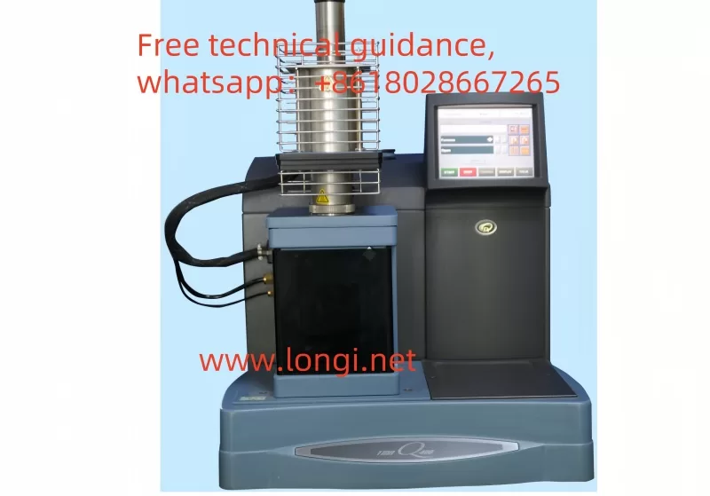
Optical System:
- The colorimeter typically consists of a light source, a sample, and a detector (or sensor).
- The light source emits light (which can be white light or specific wavelengths, such as the D65 light source simulating natural lighting conditions), and the light passes through or reflects off the sample before being received by the detector.
Color Detection:
- The detector usually has three channels corresponding to red, green, and blue.
- Each detector is calibrated to respond to specific wavelengths associated with its respective color channel.
- The detected light intensities are used to calculate the object’s tristimulus values (X, Y, Z), representing the object’s color in a standardized color space (e.g., CIE XYZ color space).
Color Space:
- The colorimeter can convert between different color spaces (e.g., RGB, Lab, LCH, etc.).
- The Lab color space is one of the commonly used spaces, consisting of lightness (L), the a-axis (red-green axis), and the b-axis (yellow-blue axis).
Color Difference Calculation:
- The colorimeter assesses color consistency by measuring the difference between the sample and a standard sample.
- It first measures the color information of the standard sample as a reference, then measures the color information of the test sample, and compares the two.
- The color difference value is calculated using mathematical algorithms (such as ΔE*ab) to evaluate the degree of color difference in the sample.
II. Usage Instructions for Colorimeter
- Warm-up:
- Turn on the colorimeter and allow it to warm up for a specified time (e.g., 30 minutes) to ensure stable performance.
- Calibration:
- Calibrate the instrument according to the manual before measurements to ensure accuracy.
- Calibration typically includes zero calibration and white calibration steps.
- Select Color Parameters:
- Choose the appropriate color parameters (e.g., CIE Lab*, CIE LCh) based on measurement needs.
- Place the Sample:
- Position the test sample on the measurement platform, ensuring it is flat, without reflection or impurities.
- For opaque samples, place them on a black background for measurement.
- Set Measurement Mode:
- Choose the suitable measurement mode (e.g., standard mode, quick mode) based on actual requirements and set parameters such as light source and observation angle.
- Start Measurement:
- Follow the manual’s instructions to set the measurement mode and press the start button. The instrument will measure automatically.
- Record Data:
- After measurement, the instrument will display the results. Record relevant data (e.g., L, a, b* values) as needed for further analysis.
- Clean the Instrument:
- Clean the instrument’s surface and internal parts promptly after use to maintain cleanliness.
- Shutdown and Storage:
- Turn off the instrument after all measurements. Store it in a dry, cool place, avoiding direct sunlight and humid environments.
III. Common Faults and Repair Methods
1. Light Source Issues:
- Fault Manifestation: Damaged light source, failure to illuminate, or insufficient brightness.
- Possible Causes: Damaged light source, poor line connection, insufficient battery power, or damaged battery.
- Repair Methods:
- Check and replace the light source (e.g., pulsed xenon lamp or tungsten bulb).
- Check line connections for proper contact.
- Replace or recharge the battery.
2. Battery Issues:
- Fault Manifestation: Insufficient battery power, failure to charge, or damaged battery causing instrument malfunction.
- Possible Causes: Aging battery, incorrect battery installation, poor battery contact.
- Repair Methods:
- Install the battery correctly.
- Check battery power and recharge or replace as needed.
3. Display Issues:
- Fault Manifestation: LCD screen failure or abnormal display.
- Possible Causes: No battery installed, insufficient battery power, incorrect battery installation, line fault.
- Repair Methods:
- Install the battery or connect the AC adapter correctly.
- Check and repair line faults.
4. Key Malfunctions:
- Fault Manifestation: Measurement buttons or body keys not functioning.
- Possible Causes: Damaged keys, charging in progress, or connection to a PC application.
- Repair Methods:
- Ensure to press the measurement button when the READY indicator is on after charging.
- Disconnect from the PC application.
- Replace damaged keys or have them repaired by professionals.
5. Connection Issues:
- Fault Manifestation: Failure to connect to PC applications or printers.
- Possible Causes: Incorrect connection method, multiple instruments connected in the PC.
- Repair Methods:
- Connect to the PC correctly, ensuring only one instrument is connected.
- Select the correct connection option from the settings screen (e.g., “USB Connection” → “PC” or “Printer”).
6. Indicator and Buzzer Issues:
- Fault Manifestation: LED indicator not lighting up, buzzer not sounding.
- Possible Causes: Settings issue (e.g., set to “off”).
- Repair Methods:
- Connect to the PC application and check/modify relevant settings.
7. Calibration Issues:
- Fault Manifestation: Colorimeter unable to complete calibration or inaccurate calibration results.
- Possible Causes: Worn, contaminated, or discolored calibration white board, or incorrect execution of the calibration process.
- Repair Methods:
- Clean or replace the calibration white board.
- Follow the manual to execute the calibration process correctly.
8. System Faults:
- Fault Manifestation: General system errors, instrument malfunction.
- Possible Causes: Aging bulb, aging circuit board, software issues.
- Repair Methods:
- Replace the bulb or circuit board.
- Upgrade or restore software to the latest version.
- For complex issues, contact Longi Ectromechanical Company or a professional repair team for inspection and repair.
IV. Brands and Models of Colorimeters Repaired by Longi Ectromechanical Company
- Datacolor:
- Datacolor 600
- Check 3
- SpyderX Elite
- ColorReader Pro
- SpectraVision Spectro 700
- SpectraVision Spectro 1000
- Konica Minolta:
- CM-700d
- CM-600d
- CM-5
- CM-3600A
- CM-3610A
- CM-25d
- CM-26dG
- X-Rite:
- Ci64
- Ci7600
- Ci7800
- eXact Standard
- eXact Advanced
- RM200QC
- HunterLab:
- UltraScan PRO
- ColorFlex EZ
- LabScan XE
- MiniScan EZ 4500L
- Vista
- BYK-Gardner:
- spectro2guide
- spectro-guide
- micro-gloss
- color-guide
- 3NH (ThreeNH):
- YS6060
- NH310
- TS7600
- NS800
- NH300
- PCE Instruments:
- PCE-CSM 8
- PCE-CSM 10
- PCE-CSM 20
- PCE-TCD 100
- Hach:
- DR1900
- DR6000
Longi Ectromechanical Company has nearly 30 years of experience in repairing colorimeters, enabling swift repairs for various instruments. Additionally, we recycle and sell used colorimeters. For more information, please feel free to contact us.