
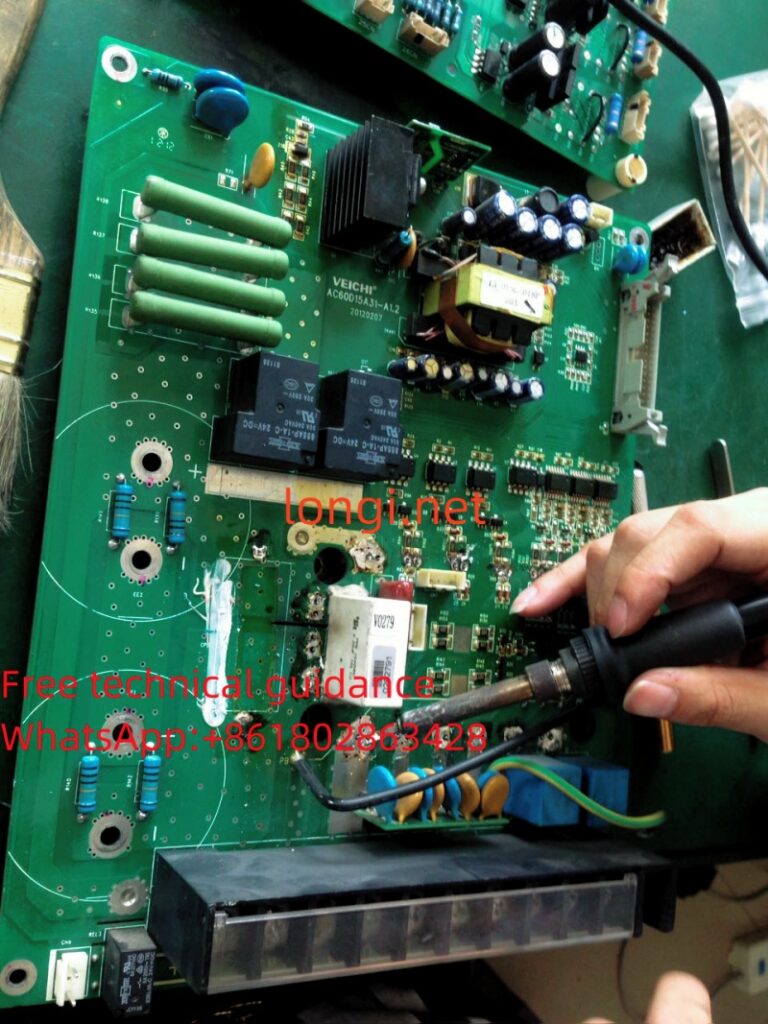
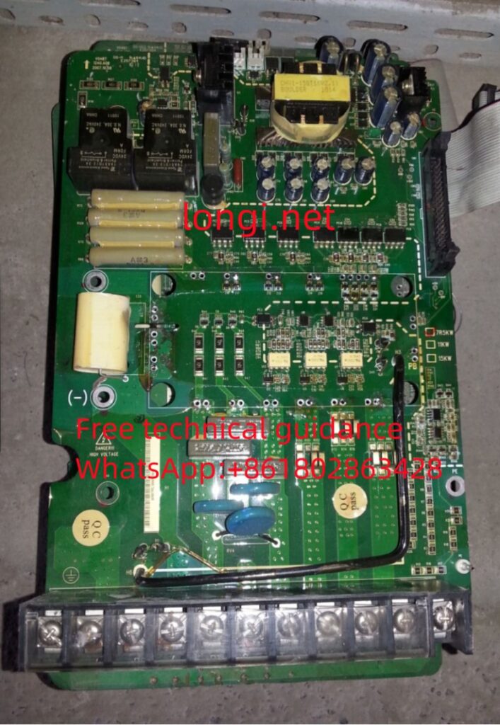
(A) Power Supply Fault Inspection:
Fault Status: After powering on, the entire device does not respond, and the operation display panel shows no display. The measured 24V and 10V control power at the control terminals are both 0V.
Fault Essence: The VFD’s switching power supply is not working.
Troubleshooting Approach: (1) Switching voltage fault; (2) Pre-charging circuit fault.
Troubleshooting Method:
(1) First check the power supply source of the switching power supply and whether the DC loop has a normal 530V voltage. If the DC loop voltage is 0V, it indicates a fault in the pre-charging circuit, such as an open charging resistor, damaged half-wave rectifier circuit, or poor contact of the normally closed contact of the contactor or relay. Repair the pre-charging circuit first and then check the fault of the switching power supply. Often, after repairing the pre-charging circuit, the VFD is also repaired. It is not necessary to focus too much on the switching power supply circuit at first.
(2) If the 530V, 265V, or 300V DC power supply for the switching power supply is available, do not focus too much on its voltage stabilization and oscillation circuit. First, check if there are any faults such as short circuits in the secondary load circuit of the switching transformer, such as a damaged cooling fan, an IC short circuit in the fault detection circuit, or a breakdown of the rectifier diode. The fault rate on the load side of the switching power supply is higher, while the problems in the oscillation and voltage stabilization links are less common.
The troubleshooting approach and order determine the efficiency of the repair work. From the perspective of the entire circuit, checking the pre-charging circuit is a very important step and should be the first consideration when troubleshooting the fault of a non-working switching power supply.
(B) Fault Inspection of the Inverter Pulse Circuit:
The section from the six PWM output terminals of the CPU to the intermediate buffer circuit is called the pre-stage circuit of the inverter pulse, while the drive circuit is referred to as the post-stage circuit of the inverter pulse, collectively known as the inverter pulse circuit.
Fault Conditions:
(1) Normal start-up operation, with normal output frequency indication on the operation display panel, but no three-phase output voltage.
(2) Normal start-up operation, with normal output frequency indication on the operation display panel, but unbalanced three-phase output voltage.
(3) OC fault occurs immediately after pressing the start button.
(4) OC fault occurs during operation.
(5) Light-load operation is normal, but motor with load jumps or encounters OC fault.
Essence of the Faults and Inspection Approach (Corresponding to the Five Fault Conditions):
(1) Several factors may contribute: a. Loss of +5V* power supply on the input side of the drive circuit’s optical coupler; b. Damage to the buffer of the pre-stage pulse circuit; c. Uncertainty of the CPU’s relevant control signals or damage to related control pins; d. Misoperation of the fault protection circuit, resulting in the locking of the pulse pre-stage circuit by the fault signal.
Special attention should be paid to the pre-stage circuit of the inverter pulse signal, such as tri-state triggers and buffer circuits, which may be directly controlled by voltage and current detection and protection circuits. When the protection circuit misoperates, it may clamp and block the transmission of six pulse signals. The concept of the fault protection circuit participating independently in pulse transmission control should be kept in mind. Although faults caused by a and b are more common, those caused by c and d often constitute difficult faults, and a lack of inspection approach in this regard may lead to detours in repair.
(2) Three factors may contribute: a. Damage to the opto-coupler of the drive circuit, preventing the normal transmission of inverter pulse signals; b. Increased internal resistance of the inverter module, leading to poor conduction in three upper-arm IGBT modules. Therefore, the three drive circuits may not be equipped with IGBT voltage drop detection circuits, resulting in a failure to report OC faults; c. Malfunction of the pre-stage pulse circuit or the CPU inverter pulse output pin, causing the inverter pulse to be missing in one or two channels.
Don’t focus solely on the post-stage drive circuit, as the inverter pulse of the pre-stage may not be input to the drive circuit. Especially, consider whether the module is faulty or the internal resistance of the inverter module has increased. Failing to consider factor c may also lead to difficult faults.
(3) Several factors may contribute: a. Defects in the post-stage drive circuit itself; b. Insufficient load capacity of the power supply of the drive circuit, such as loss of capacitance in filter capacitors and low efficiency of rectifying diodes (increased forward resistance and decreased reverse resistance); c. Defects in the inverter module.
Dynamic and static testing (voltage testing) of the drive circuit may appear normal, but it is necessary to test the current output capability of the drive circuit. Pay attention to factors b and c.
(4) Several factors may contribute: a. Load capacity of the drive circuit and internal resistance detection of the inverter module; b. Three-phase output current detection circuit; c. Reference voltage circuit in the fault detection circuit; d. User load-related reasons.
Pay attention to the influence of factors b, c, and d. Defects in the three-phase detection circuit itself or shifts in the operating point may cause false OC fault reports. Deviations in the reference voltage of the fault detection circuit may lead to inaccurate current detection and false OC fault reports. If all checks are fine, look for the cause on the production site, not excluding issues related to the load. Factors b and c may again fall into the category of difficult faults.
(5) Three factors may contribute: a. Insufficient current (power) output capability of the drive circuit; b. Defects in the inverter module, resulting in increased internal resistance; c. Issues with the load circuit, such as a faulty motor, not necessarily a fault of the VFD.
Abnormal operation of the VFD does not necessarily indicate a problem with the VFD itself. It is recommended that users try replacing the motor. Consider factors b and c, and sometimes factors outside the VFD.