I. Introduction to BEST Inverter FC300 Panel Functions and Parameter Settings
1.1 Introduction to Panel Functions
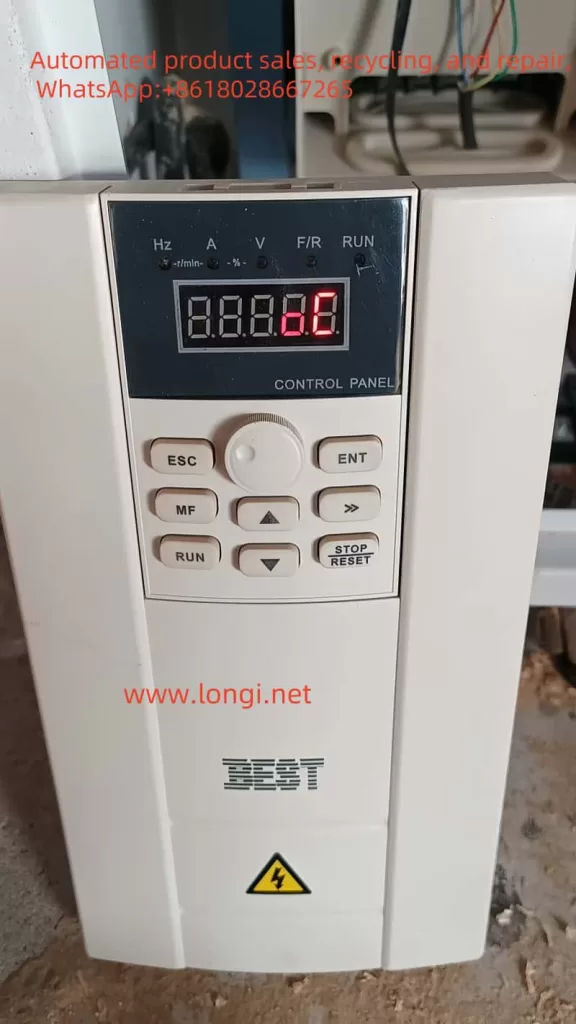
The BEST Inverter FC300’s operation panel is equipped with multiple function keys, including ESC, ENT, MF, >>, ↑, ↓, STOP/RESET, each with specific functions:
- ESC: Exits the current setting or cancels the current operation.
- ENT: Confirms the current setting or proceeds to the next operation.
- MF: Multifunction key with different functions depending on the context.
- >>: Switches between menus or parameters.
- ↑ and ↓: Adjust parameter values or scroll through menus.
- STOP/RESET: Stops the inverter operation or resets the fault status.

1.2 Parameter Initialization and Upload/Download
The BEST Inverter FC300 supports parameter initialization, upload, and download, primarily through parameter P087.
- Parameter Initialization: Set P087 to 1 and press ENT to confirm, restoring the inverter to factory settings.
- Parameter Upload: Set P087 to 4, ensure correct connection between the inverter and computer, and upload current parameter settings via dedicated software.
- Parameter Download: Set P087 to 5, ensure correct connection, and download parameters to the inverter via software.
1.3 Setting and Removing Passwords
To protect the inverter settings from unauthorized changes, the BAST FC300 supports password protection.
- Setting a Password: Set a new password in P086 and choose 2 in P087 to memorize the password.
- Removing a Password: Enter the current password in P086 and choose 3 in P087 to clear the password.
II. Terminal Start/Stop, Potentiometer Speed Adjustment, and Forward/Reverse Control
2.1 Terminal Start/Stop and Potentiometer Speed Adjustment
To achieve terminal-based start/stop of the inverter and potentiometer-based speed adjustment, correct wiring and parameter settings are required.
- Wiring: Connect the start and stop signals to the X1 and X3 terminals of the inverter, respectively (or other designated terminals, as per the manual). Connect the potentiometer to the AVI or ACI terminals for analog speed adjustment.
- Parameter Settings:
- Set P064 to 1 to select external terminal control.
- Configure the function of the AVI or ACI terminals, e.g., set P091’s X1 function to “Forward Start” and X3 to “Stop”.
- Adjust parameters like P053 as needed to set the range and mode of analog speed adjustment.

2.2 Terminal-Based Forward/Reverse Control
To achieve terminal-based forward/reverse control of the inverter, correct wiring and parameter settings are also necessary.
- Wiring: Connect the forward and reverse signals to the X1 and X2 terminals of the inverter, respectively (or other designated terminals).
- Parameter Settings:
- Ensure P064 is set to support external terminal control.
- Configure the functions of the X1 and X2 terminals, e.g., set P091’s X1 function to “Forward” and X2 to “Reverse”.
- Adjust parameters like P066 as needed to ensure motor reversal is allowed.
III. Distinction between HOC and OC Faults and Solutions
3.1 Distinction between HOC and OC Faults
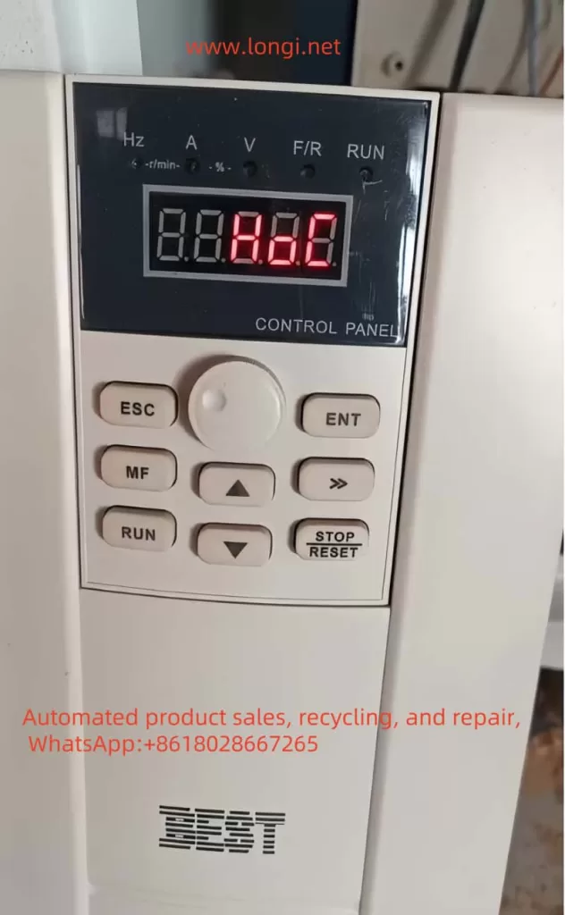
- HOC Fault: Typically refers to an overcurrent fault caused by damage to the inverter’s inverter module. This fault is severe and may be accompanied by damage to internal components of the inverter.
- OC Fault: Generally refers to an overcurrent fault on the output side, which may be caused by motor stalls, excessive loads, short acceleration times, etc.
3.2 Fault Solutions
- HOC Fault Solution:
- Check the Inverter Module: Confirm if the inverter module is damaged and replace it if necessary.
- Check the Drive Circuit: Inspect the drive circuit for normal function and troubleshoot drive faults.
- Contact the Manufacturer: If the issue is complex or unresolved, contact BAST for repair or replacement.
- OC Fault Solution:
- Check the Motor and Load: Confirm if the motor is stalled or if the load is excessive, and adjust the load or motor parameters as necessary.
- Adjust Acceleration Time: Increase the acceleration time to avoid instantaneous overcurrent during motor startup.
- Check Wiring: Verify the wiring between the motor and the inverter for correctness and eliminate any wiring errors that may cause faults.
- Reset the Inverter: Press the STOP/RESET button to reset the inverter and attempt to restart it.
IV. Conclusion
The BEST Inverter FC300, as a high-performance inverter, boasts a rich set of panel functions and flexible parameter settings, capable of meeting control demands in various complex operating conditions. Through correct wiring and parameter settings, functions such as terminal-based start/stop, potentiometer speed adjustment, and forward/reverse control can be achieved. Meanwhile, for common HOC and OC faults, users should be able to quickly identify the fault phenomenon and take corresponding measures for resolution to ensure the normal operation of the inverter. During use, users must strictly adhere to the safety precautions and operating procedures outlined in the manual to ensure the safety of personnel and equipment.
