Do you have surplus or second-hand industrial control products lying around, such as VFDs, PLCs, touch screens, servo systems, CNC systems, robots, instruments, sensors, or control panels? Longi Electromechanical is here to help you monetize your inventory quickly and efficiently, regardless of its condition or age.
With over 20 years of experience in the industry, Longi Electromechanical has built a reputation for integrity, fair dealing, and conscientious management. We take every transaction seriously and strive to offer the best possible prices to our partners.
Our procurement process is designed to be fast, convenient, and secure. We follow strict principles of confidentiality and security, ensuring that your transactions are handled with the utmost care. We offer cash payments and can even estimate a reasonable acquisition price online through pictures or videos provided by you.
Whether you prefer logistics collection, online payment, or face-to-face transactions, we’re here to accommodate your needs. So why wait? Contact Longi Electromechanical today and start accelerating your capital recovery with our high-price cash recovery services for used industrial control products!
Longi Electromechanical: Your Trusted Partner for Industrial Control Product Recycling.
Longi Electromechanical Company specializes in the repair of various types of ultrasonic equipment using advanced AI methods and a dedicated technical team. We offer component-level maintenance and can resolve common issues on the same day, minimizing downtime and maximizing customer productivity. With a vast experience of repairing over 2000 ultrasonic devices, we have honed our skills to handle a wide range of brands and models.
Produktion mit CNC-Maschine, Bohren und Schweißen und Konstruktionszeichnung im Industriebetrieb.
Contact Us: Phone/WhatsApp: +8618028667265
Key Services and Features:
Comprehensive Repair Solutions: From plastic hot plate welding machines to ultrasonic flaw detectors, we repair a diverse range of ultrasonic equipment.
Brand Expertise: We have experience with numerous brands, including Minghe, Changrong, Swiss RINCO, and many more, ensuring optimal performance restoration.
Warranty and Cost-Effectiveness: Repaired equipment comes with a one-year warranty for the same problem point, and our maintenance costs are competitive.
Quick Turnaround: We prioritize efficient repairs to get your equipment back in operation as soon as possible.
Types of Ultrasonic Equipment We Repair:
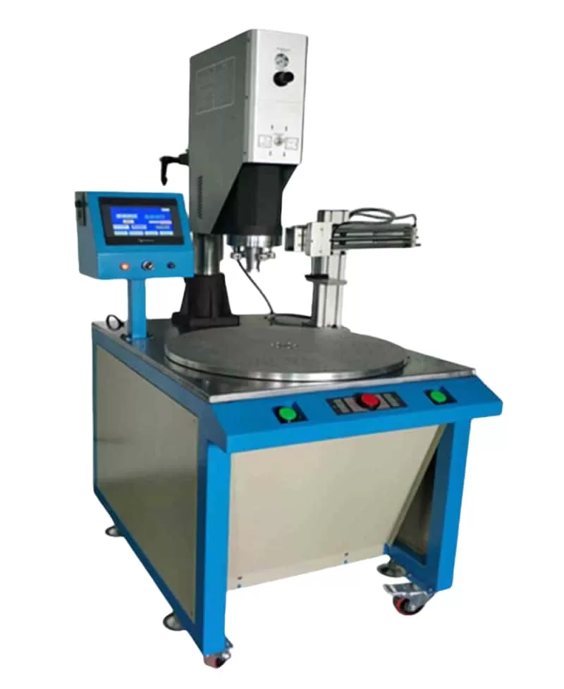
Plastic Welding Equipment: Ultrasonic welding machines, hot plate welding machines, multi-head ultrasonic welding machines, and more.
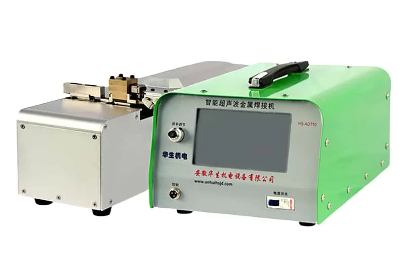
Metal Welding Equipment: Ultrasonic metal welding machines, spot welding machines, wire welding machines, and roll welding machines.
Automotive Welding Equipment: Door panel welding machines, interior part welding machines, instrument panel welding machines, and more.
Specialized Equipment: Ultrasonic flaw detectors, cutting machines, food cutting machines, tool heads, and various other ultrasonic devices.
Components and Parts: Ultrasonic vibrating plates, power boards, transducers, generators, and supporting tooling.
Common Faults We Address:
Cleaning water surface not vibrating
Debonding between vibrator and load
Mold head misalignment
No display on startup
Overload or overcurrent during welding
High current during testing
Insufficient or excessive welding heat
Vibrator leakage waves
Unresponsive buttons
Travel protection issues
Power adjustment problems
Insufficient ultrasonic intensity
Cracked transducer ceramic
Burned-out power tube
Voltage stabilization issues
Inductor and isolation transformer problems
Disconnected vibrator wire
Repair Principles:
Observe, Understand, Act: Begin by inquiring about the issue from frontline staff, checking for voltage fluctuations, and understanding the context before taking action.
Simple Before Complex: Rule out peripheral issues like the environment, electricity, load, raw materials, and molds before diving into more complex repairs.
Address Mechanical Issues First: Visible mechanical problems, such as mold issues, should be addressed before exploring electrical causes.
Trust Longi Electromechanical Company for reliable, efficient, and cost-effective ultrasonic equipment repair services. Contact us today to learn more about our services and how we can help keep your ultrasonic equipment running smoothly. WhatSapp:+8618028667265, Zalo:+8613922254854
Intelligent Precision Instrument Maintenance Base,Professional maintenance of various intelligent instruments and meters, phone/WhatsApp:+8618028667265, Mr. Guo;Zalo:+8613922254854
Longi Electromechanical specializes in repairing various imported intelligent precision instruments and meters, and has accumulated rich maintenance experience over the years, especially environmental testing instruments, electrical instruments, thermal instruments, acoustic and flow instruments, and electrical instruments. Environmental testing instruments, thermal instruments, acoustic and flow instruments, We can quickly repair radio instruments, length instruments, environmental testing equipment, quality inspection instruments, etc. Different instruments have different characteristics and functions, and their circuits and structures are also different. Even for the same instrument, if there are different faults, repairing them is still a different solution. Rongji Company has numerous high-end maintenance engineers equipped with artificial intelligence AI detection instruments, which can provide you with multi-dimensional solutions to various tricky instrument problems.
Over the years, Longi Electromechanical has repaired instruments including but not limited to:
Spectrum analyzers, network analyzers, integrated test instruments, 3D laser scanners, noise figure testers, receivers, telephone testers, high and low-frequency signal sources, audio and video signal analyzers, constant temperature and humidity chambers, thermal shock chambers, simulated transport vibration tables, mechanical vibration tables, AC grounding impedance safety testers, safety comprehensive analyzers, withstand voltage testers, battery internal resistance testers, high-precision multimeters, precision analyzers, gas and liquid analyzers, metal detectors, LCR digital bridges, oscilloscopes, electronic loads, power meters, power analyzers, multimeters, DC power supplies, AC power supplies, CNC power supplies, variable frequency power supplies, and various communication power supplies.
We have repaired the following brands:
Chroma, ITECH, Tonghui, Agilent, Tektronix, Keysight, Fluke, Keithley, Rohde & Schwarz, Lecroy, Anritsu, Rigol, and many more.
Longi Electromechanical strives to provide comprehensive repair services for a wide range of instruments and equipment, ensuring that our customers’ devices are restored to optimal performance.
Longi maintenance engineers possess over twenty years of experience in instrument repair. We have multiple engineers who excel in repairing imported precision instruments. The team works together, enabling faster troubleshooting and quick resolution of complex issues while improving the repair rate of instruments.
Spare parts are fundamental to successful repairs. Many imported instruments and meters require specialized components that cannot be easily replaced with generic market parts. Rongji Electromechanical maintains a long-term stock of electronic components for various instruments, ensuring their availability when needed.
Documentation and manuals are also crucial tools for ensuring rapid repairs. Accessing these resources allows for quick research and analysis of faults, enabling engineers to quickly identify the repair priorities. Longi Electromechanical has a long history of collecting specifications for various brands and models of instruments, greatly aiding in the repair process.
The intelligent instruments that have been carefully repaired by us can generally continue to be used for about 5 years. We promise that when the same malfunction occurs again, our repair service will provide a one-year warranty service.
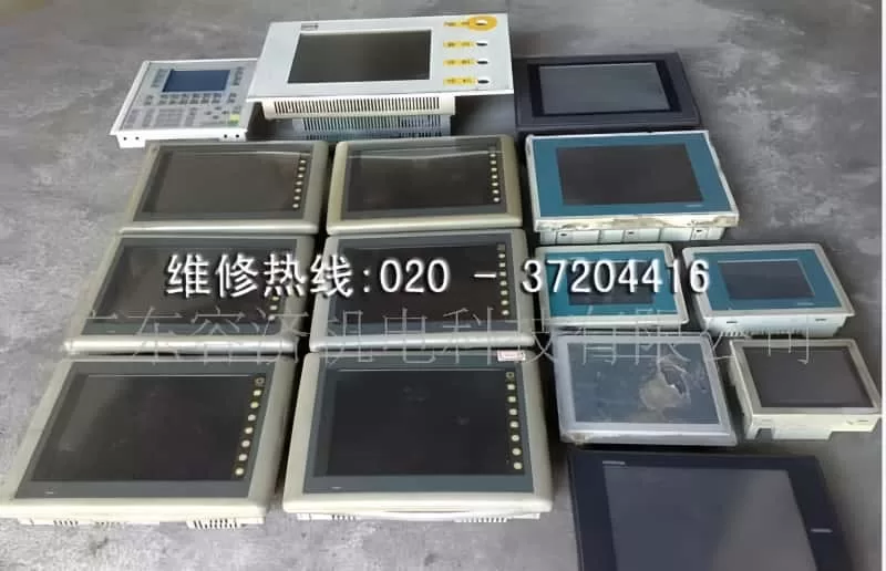
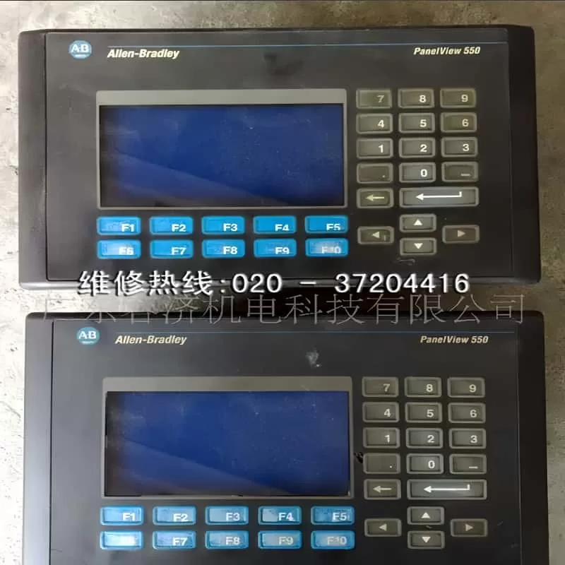
Global Touch Screen Repair Services: Expert Maintenance for All Your Touch Screen Needs
Touch screens have become an integral part of our daily lives, revolutionizing the way we interact with machines in various industries including industrial, commercial, and medical fields. These versatile devices come in different forms such as resistive, capacitive, infrared, and ultrasonic screens, each serving unique purposes. However, due to their frequent use and delicate glass structure, touch screens are prone to damage, particularly to the outer touch surface known as the “touchpad.”
For over two decades, Rongji Electromechanical Maintenance has been a trusted name in the touch screen repair industry. With extensive experience in handling touch screens across diverse sectors, we specialize in repairing both resistive and capacitive screens used in automobiles and other critical applications. Our expertise ensures that your touch screens are restored to optimal functionality, minimizing downtime and maximizing efficiency.
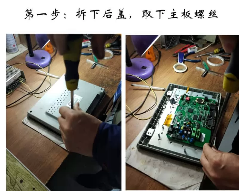
The Repair Process: A Step-by-Step Guide
Disassembly and Inspection: We begin by carefully removing the back cover and motherboard screws of the touch screen. This step allows us to access the internal components and assess the extent of the damage.
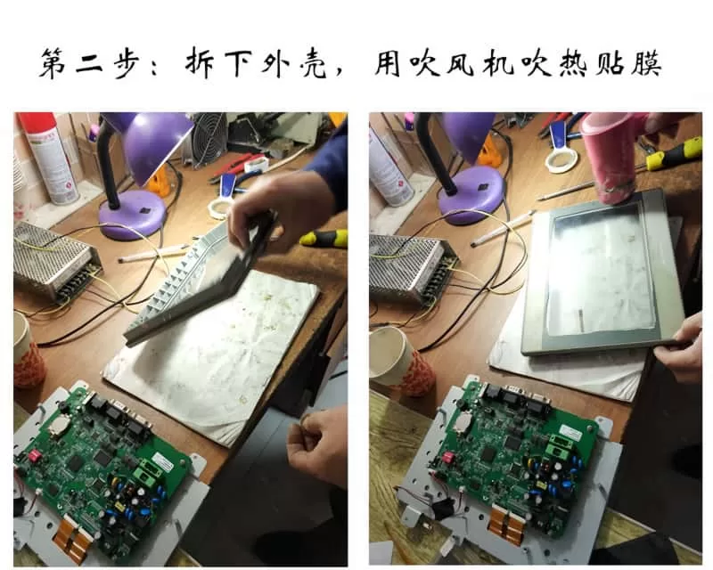
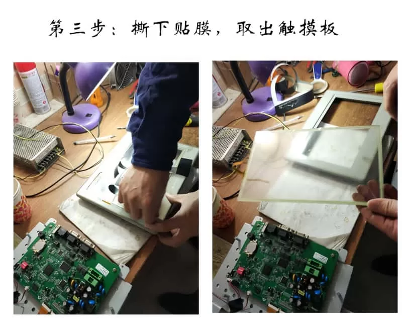
Heating and Peeling: Our skilled technicians use a hair dryer to gently heat the film adhering to the touch screen. This softens the adhesive, making it easier to peel off the outer layer without causing further damage.
Touchpad Replacement: Once the old touchpad is removed, we replace it with a high-quality touchpad from our inventory. Longi Electromechanical Company has reverse-engineered various touch screen models, ensuring that our replacement parts are fully compatible with the original equipment.
Reassembly: We apply double-sided tape to the touch screen border and securely attach the new touchpad. This ensures a perfect fit and optimal performance.
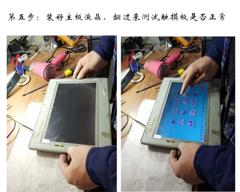
Testing and Fine-Tuning: With the new touchpad in place, we reinstall the motherboard and LCD, then flip the unit over to test its functionality. Our rigorous testing process ensures that the touch screen operates smoothly and accurately.
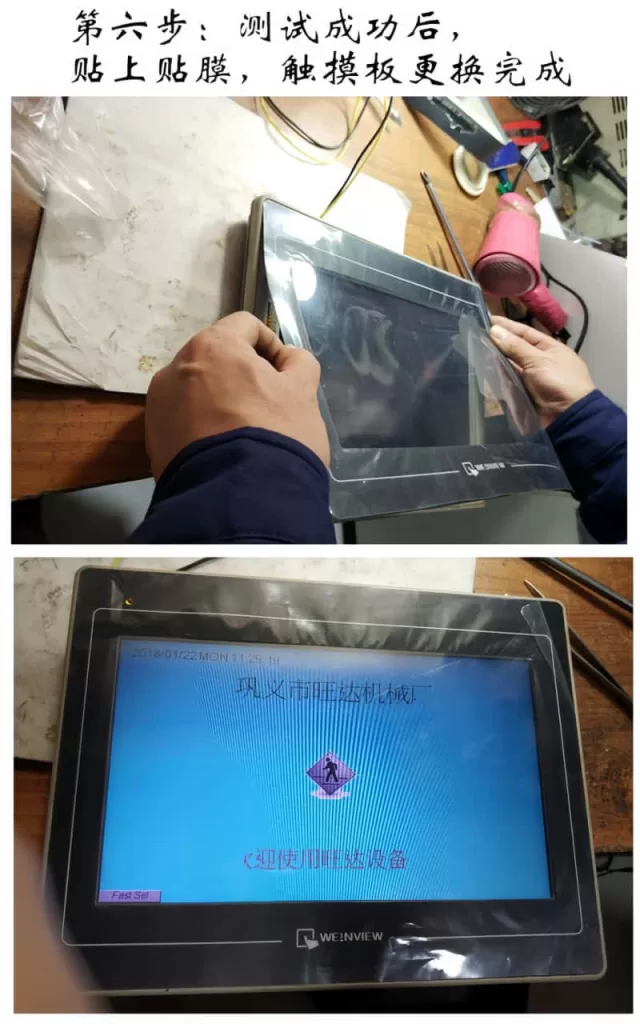
Final Assembly and Quality Check: After successful testing, we apply a protective film to the touch screen and reassemble the unit. A final quality check is performed to ensure that the repair meets our high standards.
Addressing Complex Issues
In addition to touchpad replacements, we also handle more complex issues such as circuit failures and software problems. Our team uses professional software analysis and hardware processing techniques to diagnose and repair these issues, ensuring that your touch screen is fully restored to its original state.
Our Repair Services Cover a Wide Range of Brands
At Rongji Electromechanical Company, we have repaired touch screens from numerous brands including Siemens, Proface, Mitsubishi, Fuji, Panasonic, OMRON, and many more. Our extensive experience and expertise enable us to provide reliable repair services for a wide variety of touch screen models.
Common Touch Screen Problems We Solve
Unresponsive Touch Screen: If your touch screen is visible but cannot be touched or clicked, it may be due to a faulty touch panel. Our experts can replace the panel to restore functionality.
No Display: If your touch screen does not display anything and the indicator lights are off, it could be a power supply issue. We can diagnose and repair the problem to get your touch screen back up and running.
Black Screen: If your touch screen functions but displays a black screen, it may be due to a burned-out backlight tube. We can replace the tube to restore the display.
Distorted Image or Abnormal Colors: Issues with the LCD or connecting cables can cause distorted images or abnormal colors. Our technicians can diagnose and repair these issues to ensure clear and accurate display.
Communication Errors: If your touch screen displays a communication error and responds slowly to touch, it may be due to issues with the PLC or other connected devices. We can troubleshoot and repair the connection to ensure smooth communication.
Choose Rongji Electromechanical Maintenance for reliable and professional touch screen repair services. Contact us today to learn more about our services and how we can help you keep your touch screens in optimal condition.WhatSapp:+8618028667265 ;Zalo:+8613922254854
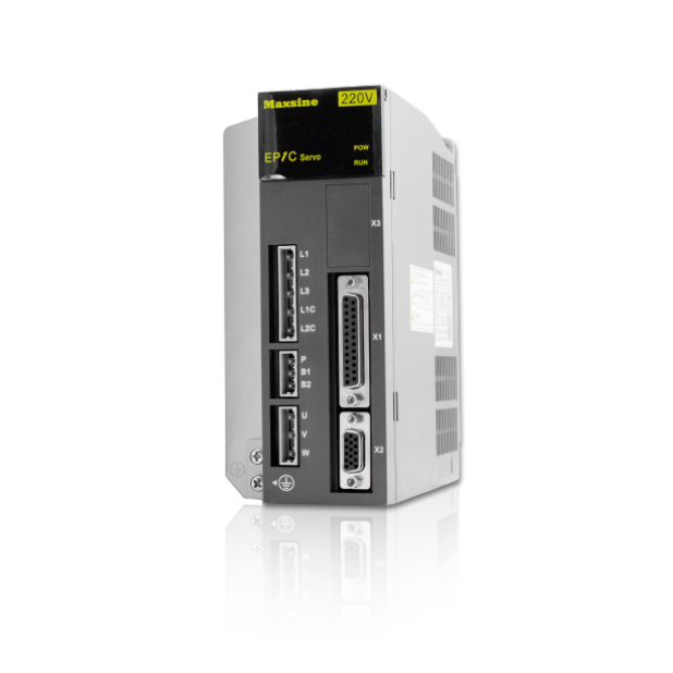
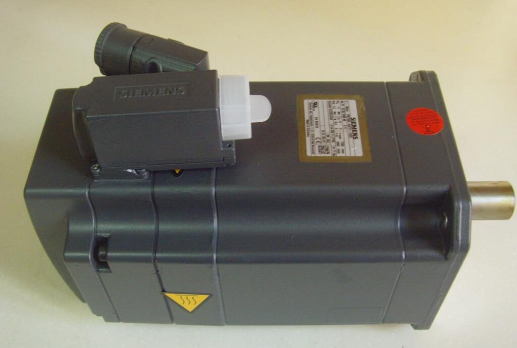
Global Servo CNC maintenance center,Professional maintenance of servo CNC systems
Remember to contact Longi Electromechanical for any issues with servo and CNC systems!
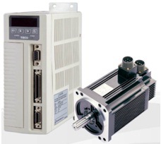
Servo systems differ from VFDs in that they offer higher precision and typically come with delicate encoders. Servo motors are synchronous motors with magnets inside, and if not handled carefully during disassembly and assembly, their original performance may not be restored. Additionally, different servo drivers cannot be used interchangeably with other servo motors. This means that during the repair of a servo driver, a corresponding servo motor and cable plug are required for proper testing. Similarly, repairing a servo motor also requires a matching servo driver for testing, which can pose challenges for many maintenance personnel.
As for CNC (Computer Numerical Control) systems, most are embedded industrial computer types with closed control systems. Each manufacturer has its own design ideas, programming methods, wiring, and communication architectures, making them incompatible with one another.
Longi Electromechanical Company has designed various styles of servo and CNC maintenance test benches to test the working conditions of different CNC systems, servo drivers, or servo motors. When servo systems encounter issues such as no display, phase loss, overvoltage, undervoltage, overcurrent, grounding, overload, module explosion, magnet loss, parameter errors, encoder failures, communication alarms, etc., the corresponding platform can be used to test and diagnose the problem.
Repair Hotline: +8618028667265 Mr. Guo; Zalo:+8613922254854
After resolving these issues, the servo system also needs to undergo a simulated load test to avoid problems such as overcurrent under load conditions, even if it performs well under no-load conditions. This ensures that the servo system is fully functional and ready for use in actual applications.
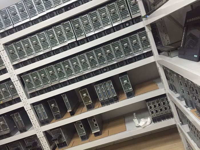
For the CNC system, it is also necessary to conduct simulated operation before normal delivery to avoid any discrepancy with the on-site parameters. Currently, Rongji Electromechanical possesses hundreds of servo and CNC test benches, which can quickly identify problem areas and promptly resolve issues. With these advanced testing facilities, Longi Electromechanical ensures the smooth operation and reliability of the repaired equipment.
The Servo and CNC Repair Center established by Longi Company currently has over 20 skilled and experienced maintenance engineers who specialize in providing repair services for different brands and specifications of servo and CNC systems. They implement tailored repair solutions for different maintenance projects, ensuring efficient and high-quality service for customers. By helping customers save valuable production time and reducing their maintenance costs, Rongji truly cares about the urgent needs of its customers and strives for common development and progress together.
We have repaired the following brands of servo and CNC systems:
Servo Systems
Lenze Servo Systems
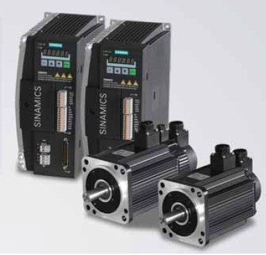
Siemens Servo Systems
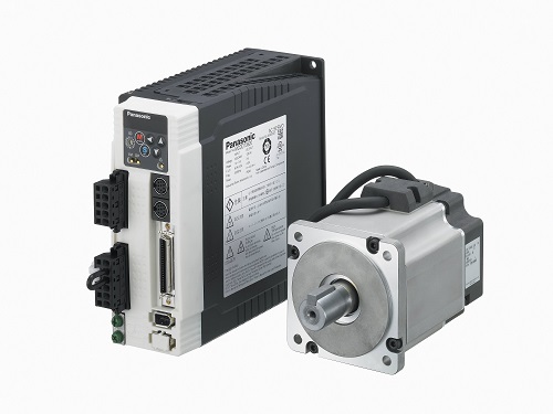
Panasonic Servo Systems
Eurotherm Servo Systems
Yaskawa Servo Systems
Fuji Servo Systems
Delta Servo Systems
Omron Servo Systems
Fanuc Servo Systems
Moog Servo Systems
TECO Servo Systems
Norgren Servo Systems
SSB Servo Drive Systems
Hitachi Servo Systems
Toshiba Servo Systems
Denso Servo Systems
Parvex Servo Systems
CNC Systems
Mitsubishi Servo Systems
Sanyo Servo Systems
Mitsubishi CNC (MITSUBISHI)
Fanuc CNC (FANUC)
Siemens CNC (SIEMENS)
Brother CNC (BROTHER)
Mazak CNC (MAZAK)
GSK (Guangzhou Numerical Control)
Huazhong Numerical Control
Fagor CNC
Heidenhain
Haas CNC
NUM (France)
Hurco (USA)
KND (Beijing KND Technology Co., Ltd.)
Leadshine
Syntec
Shenyang Machine Tool i5 *凯恩帝 (KND)
Note: Some of the brand names mentioned may be trademarks or registered trademarks of their respective owners. The listing here is for informational purposes only and does not imply any affiliation or endorsement by Rongji Electromechanical or any of the mentioned brands.
Machine Tool Brands
(1) European and American Machine Tools:
Gildemeister
Cincinnati
Fidia
Hardinge
Micron
Giddings
Fadal
Hermle
Pittler
Gleason
Thyssen Group
Mandelli
Sachman
Bridgeport
Hueller-Hille
Starrag
Heckert
Emag
Milltronics
Hass
Strojimport
Spinner
Parpas
(2) Japanese and Korean Machine Tools:
Makino
Mazak
Okuma
Nigata
SNK
Koyo Machinery Industry
Hyundai Heavy Industries
Daewoo Machine Tool
Mori Seiki
Mectron
(3) Taiwanese and Hong Kong Machine Tools:
Hardford
Yang Iron Machine Tool
Leadwell
Taichung Precision Machinery
Dick Lyons
Feeler
Chen Ho Iron Works
Chi Fa Machinery
Hunghsin Precision Machinery
Johnford
Kaofong Industrial
Tong-Tai Machinery
OUMA Technology
Yeongchin Machinery Industry
AWEA
Kaoming Precision Machinery
Jiate Machinery
Leeport (Hong Kong)
Protechnic (Hong Kong)
(4) Chinese Mainland Machine Tools:
Guilin Machine Tool
Yunnan Machine Tool
Beijing No.2 Machine Tool Plant
Beijing No.3 Machine Tool Plant
Tianjin No.1 Machine Tool Plant
Shenyang No.1 Machine Tool Plant
Jinan No.1 Machine Tool Plant
Qinghai No.1 Machine Tool Plant
Changzhou Machine Tool Factory
Zongheng International (formerly Nantong Machine Tool)
Dahe Machine Tool Plant
Baoji Machine Tool Plant
Guilin No.2 Machine Tool Plant
Wanjia Machine Tool Co., Ltd.
Tianjin Delian Machine Tool Service Co., Ltd.
Note: The list provided above is comprehensive but not exhaustive. Machine tool brands and manufacturers are constantly evolving, and new players may have emerged since the compilation of this list. Always refer to the latest industry updates for the most accurate information.
“Longi Electromechanical” has more than 20 years of experience in industrial control maintenance, and is one of the earliest companies engaged in VFD repair. Equipped with artificial intelligence AI maintenance instruments, it specializes in emergency repair of various equipment, with high technical efficiency. It has repaired more than 200,000 units of equipment, including ultrasonic, robot, charging pile, inverter,Variable Frequency Drive (VFD), touch screen, servo, intelligent instrument, industrial control machine, PLC and other products. General problems can be repaired on the same day. LONGI promises you that “if it can’t be repaired, we won’t charge you”. And it provides lifelong maintenance service and free technical consultation for inspection! For urgent repair consultation, please call the contact number or add WHATSAPP maintenance hotline: +8618028667265 Mr. Guo;Zalo:+8613922254854
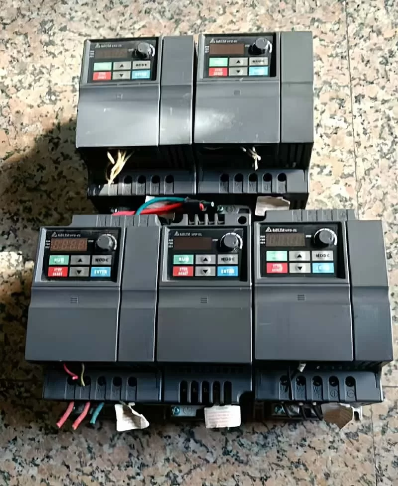
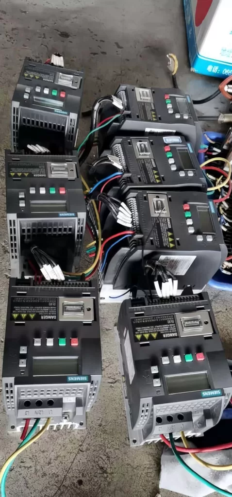
From European and American brands to Japanese, Korean, and Taiwanese ones, until various domestic brands, we have repaired countless models and specifications of VFDs. In the process of serving our customers, we have continuously learned and accumulated maintenance experience to enhance our skills. We specialize not only in repairing VFDs but also in summarizing various maintenance experiences, elevating them to a theoretical level. We have published the book “VFD Maintenance Technology” and offered VFD maintenance training, thereby promoting the development of the VFD maintenance industry. Longi Electromechanical Company has repaired VFDs from the following brands:
Other brands: Migao VFD, Rongqi VFD, Kaiqi VFD, Shiyunjie VFD, Huichuan VFD, Yuzhang VFD, Tianchong VFD, Rongshang Tongda VFD, LG VFD, Hyundai VFD, Daewoo VFD, Samsung VFD, etc.
Longi Electromechanical Company specializes in the maintenance of VFDs and strictly requires its engineers to followlow standard operating procedures. Upon receiving a unit, the engineers carefully inspect its exterior and clarify any fault conditions with the customer before beginning work. Any removed circuit boards are cleaned using ultrasonic cleaning equipment. Repaired circuit boards are coated with high-temperature and high-pressure-resistant insulating paint, dried in a drying machine, and then reinstalled in the VFD, with measures taken to prevent corrosion and interference.
The repaired VFD will undergo a simulated operation with load using a heavy-load test bench to avoid any potential issues that may arise under actual load conditions on site.
When it comes to VFD maintenance, most cases are related to the equipment on site. Sometimes a standalone unit may have been repaired, but it doesn’t work properly when installed on site. In some cases, the problem lies with the system rather than the VFD itself. For such issues, if the customer requests on-site service, we will do our utmost to resolve the problem for them. If the location is far away, such as in another province, we can use tools like video conferencing and phone calls to allow our engineers to remotely diagnose and resolve the on-site issues for the customer.
As a professional company engaged in the sales and services of second-hand industrial control products, we are committed to providing high-quality and performance-oriented second-hand industrial control products to help customers improve production efficiency and reduce costs. The company was founded in 2000 and has gradually become a leading supplier of second-hand industrial control products in the industry through years of development.
Our product range is diverse, including second-hand frequency converters, PLCs, servo drivers, servo motors, industrial touch screens, instruments and meters. These products have undergone strict selection and testing to ensure that their performance and reliability meet the expectations of customers. We believe that these products will be able to meet your various needs and bring huge value to your industrial automation process.
In terms of technical services, we promise to provide customers with comprehensive engineering technical services. Whether you encounter any problems in the process of purchasing products or technical difficulties during operation, we will provide you with timely and professional support. Our technical team will provide you with the most appropriate solution based on your specific situation to ensure the smooth implementation of your project.
To ensure the reliable quality of the products purchased by customers, we provide a three-month warranty service. During the warranty period, if the product has a quality problem, we will provide free maintenance or replacement services for you. Our warranty service aims to allow customers to purchase and use with confidence, making your purchasing experience more pleasant.
If you have any questions or needs about our products or services, please feel free to contact us. You can contact us through telephone, email or visiting our office address. We will serve you wholeheartedly and look forward to cooperating with you.
In conclusion, as a professional second-hand industrial control product company, we use high-quality products, perfect services, and reliable warranties to accompany your industrial automation process. We believe that cooperating with us will be a wise choice for you, and we will do our best to help you achieve your business goals.
The ANYHZ Inverter FST-650 Series stands out as a leader among general-purpose frequency converters, thanks to its high performance and extensive parameter features. This document aims to provide users with a comprehensive operational guide, covering aspects such as the operation panel functions, parameter settings, external control, and fault handling, to assist users in efficiently utilizing and maintaining this inverter.
II. Detailed Explanation of Operation Panel Functions
(I) Basic Functions of the Operation Panel
The operation panel of the FST-650 Series inverter is intuitively designed and comprehensive in functionality, including:
Program Key: Used to enter or exit menus.
Confirm Key: Navigates through menus step-by-step, sets, and confirms parameters.
Up/Down Keys: Adjust data and function codes.
Right Shift Key: Shifts right to select parameters when the inverter is stopped or in the operation interface; selects the digit to modify when changing parameters.
Run Key: Starts the inverter in keyboard operation mode.
Stop/Reset Key: Stops the operation in the running state; resets the inverter during a fault alarm.
(II) Restoring Factory Parameter Settings
Enter the parameter setting interface and locate F0.00.
Set F0.00 to the default value (usually 0).
Confirm the setting, and the inverter will restore to factory default settings.
(III) Password Setting and Removal
Enter the parameter setting interface and find FP.00.
Enter a new password and confirm.
To remove the password, set FP.00 to the default value (usually 0).
(IV) Parameter Access Restriction
Enter the parameter setting interface and locate FP.01.
Set the parameter access restriction level and confirm.
Users with different levels will have different access and modification permissions for parameters.
III. External Terminal Control and Potentiometer Speed Regulation
(I) External Terminal Forward/Reverse Control
Terminal Connections: X1 (Forward Run FWD), X2 (Reverse Run REV).
Parameter Settings:
Enter the parameter setting interface and find F4.00 and F4.01.
Set F4.00 to 1 (Forward) and F4.01 to 2 (Reverse).
Confirm the settings, and the inverter will control forward/reverse based on the external terminal status.
(II) External Potentiometer Speed Regulation
Terminal Connections: AI1 (Analog Input Terminal, connected to the potentiometer).
Parameter Settings:
Enter the parameter setting interface and find F0.03.
Set F0.03 to 2 (Analog VCI Setting).
Confirm the setting, and the inverter will regulate speed based on the potentiometer input signal.
IV. Fault Codes and Handling Methods
(I) Common Fault Codes
Err01: Overcurrent Fault
Err02: Overvoltage Fault
Err03: Undervoltage Fault
Err04: Overheat Fault
Err05: Phase Sequence Fault
Err06: Ground Fault
(II) Fault Handling Methods
Err01: Check the load and cable connections to ensure the load is within the allowable range.
Err02: Check the input voltage and cable connections to ensure the voltage is within the allowable range.
Err03: Check the input voltage and cable connections to ensure the voltage does not fall below the set value.
Err04: Check the inverter’s cooling conditions to ensure proper ventilation and that the heat sink is functioning correctly.
Err05: Check the input power phase sequence and cable connections to ensure the phase sequence is correct.
Err06: Check the ground connection and cable connections to ensure the ground is properly connected.
V. Conclusion
The ANYHZ Inverter FST-650 Series offers users a highly efficient and stable frequency conversion solution with its powerful features and flexible control methods. By mastering the operation panel functions, parameter settings, external control, and fault handling methods, users can fully leverage the performance advantages of this inverter and ensure its long-term stable operation. It is hoped that this document will provide strong support for users in using and maintaining the FST-650 Series inverter.
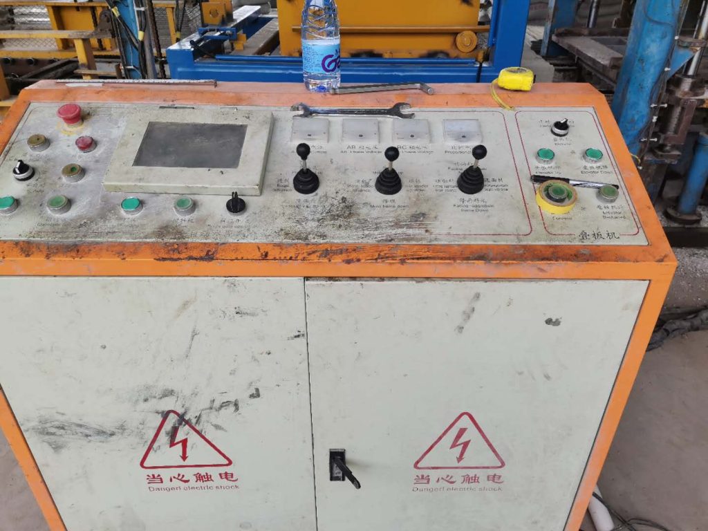
The control panel of the LS Servo APD-VS series is designed to be intuitive, comprising the following key components:
Operation Keys:
Left/Right Keys: Used to switch between menu items for easy navigation.
Up Key: Selects submenus or adjusts parameter values.
Enter Key: Confirms selections or enters edit mode, executing commands such as tests or alarm resets. Display Screen: Displays real-time system operating status, including key parameters such as current speed, position, torque, and load, facilitating user monitoring and diagnostics. Menu Structure:
Status Menu (Pd-001 to Pd-020): Displays real-time data such as operating status, speed, torque, and load.
Alarm Menu (PA-101 to PA-120): Records historical alarms for fault tracing.
System Menu (PE-201 to PE-220): Configures system parameters, such as motor ID, encoder type, and communication speed.
Control Menu (PE-301 to PE-320): Adjusts control parameters, such as inertia ratio, position/speed gain, and resonance suppression.
Analog Menu (PE-401 to PE-420): Sets analog inputs/outputs, such as speed and torque commands.
Input/Output Menu (PE-501 to PE-520): Manages I/O settings, including position error limits and brake control.
Speed Operation Menu (PE-601 to PE-620): Configures speed-related operations and test runs.
Pulse Operation Menu (PE-701 to PE-720): Handles position control settings, including pulse logic and electronic gear ratio.
Command Menu (PC-801 to PC-820): Executes operations such as alarm reset, test run, and gain adjustment. Connectors:
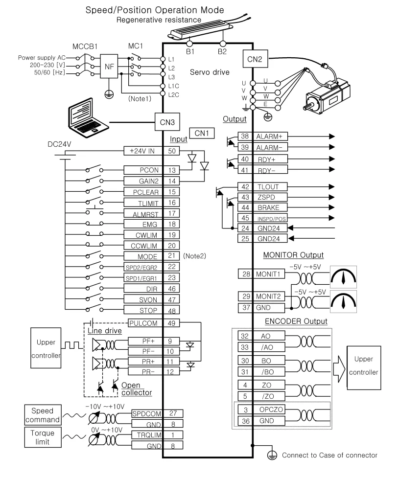
CN1 (Control Signal): Used to connect external control signals, supporting communication with a host computer or PLC.
CN2 (Encoder): Connects to the encoder, providing motor position and speed feedback.
CN3 (Communication): Supports RS232 or other communication protocols for interaction with a PC or host controller.
II. Setting Passwords and Access Restrictions
The LS Servo APD-VS series user manual does not explicitly mention a traditional password system but provides a “Menu Data Lock” function to restrict unauthorized parameter modifications:
Menu Data Lock Function:
Enable or disable the lock function through menu [PC-810].
In the locked state, attempting to modify menu data will display an “Err3” error, indicating that the menu is locked.
Unlocking Operation: Return to [PC-810] and press the Enter key to switch to the “unLock” state, allowing parameter modifications.
III. Jog Operation
Jog operation (also known as manual test operation) is an important function for testing motor response or debugging. Below are the detailed steps:
Starting Jog:
Enter command menu [PC-803] and press the Enter key to initiate the manual test.
The system will cancel existing alarms, display the test operation speed, and start the motor. Controlling Speed and Direction:
Use the Up key to switch between different test speeds set in [PE-602] to [PE-608].
Press the Right key for forward rotation (counterclockwise) and the Left key for reverse rotation (clockwise). Ending Operation:
Press the Enter key to stop the test and return to the menu.
IV. Position Mode and External Pulse Forward/Reverse Control
Position mode is suitable for applications requiring precise positioning, such as CNC machine tools or robotic arms. Below are the steps to configure external pulse forward/reverse control:
Setting Position Mode:
Set the operation mode to “2” (position mode) in menu [PE-601]. Pulse Input:
External pulse signals are input through pins 9 (PF+), 10 (PF-), 11 (PR+), and 12 (PR-) of CN1.
Two input methods are supported: line-driven 5V or open-drain 24V, to be selected based on the host controller. Electronic Gear Ratio:
Use [PE-702] to [PE-709] to set the electronic gear ratio, defining the ratio between input pulses and encoder pulses. Pulse Logic:
Set the pulse logic to N logic or P logic in [PE-701], determining the pulse direction interpretation for forward/reverse rotation.
V. Speed Mode and Forward/Reverse Control
Speed mode is used to control motor speed and is suitable for applications requiring stable speed. Below are the configuration steps:
Setting Speed Mode:
Set the operation mode to “1” (speed mode) in menu [PE-601]. Speed Command:
Analog Command: Input through SPDCOM (pin 27), with a range of -10V to +10V, where positive and negative values correspond to forward and reverse directions, respectively.
Digital Command: Select digital speed commands 1 to 7 through combinations of SPD1 (pin 23), SPD2 (pin 22), and SPD3 (pin 21). Direction Control:
Use DIR (pin 46) and STOP (pin 48) inputs to control direction, configured through [PE-514].
VI. Fault Code Analysis and Solutions
The LS Servo APD-VS series provides a detailed list of fault codes to help users quickly diagnose and resolve issues. Below are common fault codes and their solutions:
Fault Code
Meaning
Solution
Nor-off
Normal (servo off)
No action required
Nor-on
Normal (servo on)
No action required
L1.01
RS232 communication error/control operation error
Replace the drive
AL-01
Emergency stop
Check external DC24V power supply
AL-02
Power failure
Check main power lines
AL-03
Line fault
Check settings, CN2, U/V/W lines
AL-04
Motor output fault
Check U/V/W lines and IPM module
AL-05
Encoder pulse error
Check [PE-204] settings and CN2 lines
AL-06
Following error
Check [PE-502] settings, lines, limit switches, gain
AL-08
Overcurrent
Check output lines, motor/encoder settings, gain; replace the drive if necessary
I. Introduction to the Operation Panel Functions and Basic Settings of the Inverter
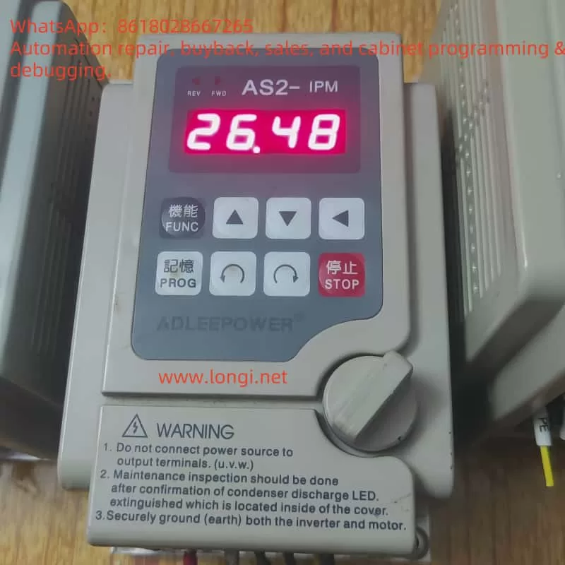
The ADLEEPOWER AS series inverter is a high-performance, multifunctional inverter with an intuitive operation panel and rich features. The operation panel mainly includes the following function keys:
FWD/RUN: Forward run key. Pressing this key will rotate the motor in the forward direction.
REV/RUN: Reverse run key. Pressing this key will rotate the motor in the reverse direction.
SHIFT: Shift key. Used to switch the position of digits during parameter setting.
UP/DOWN: Up/down keys. Used to increase or decrease values during parameter setting.
PROG: Memory key. Used to save the currently set parameters.
FUNC: Function key. Used to select the function to be set.
STOP: Stop key. Pressing this key will stop the motor and return it to standby mode.
Restoring Factory Default Parameters
To restore the inverter’s parameters to factory defaults, follow these steps:
Press the PROG key to enter parameter setting mode.
Use the UP/DOWN keys to find the CD52 parameter (regional version).
Press the FUNC key to enter parameter modification mode.
Use the UP/DOWN keys to set the CD52 parameter to USA (for the US version) or Eur (for the European version), then press the PROG key to save.
Power off and restart the inverter. The parameters will be restored to factory defaults.
Setting and Removing Passwords
The AS series inverter supports password protection to prevent unauthorized parameter modifications. To set a password, follow these steps:
(Note: The specific password setting method may vary depending on the model. The following are general steps.)
Enter parameter setting mode.
Find the parameter related to password setting (refer to the user manual of the specific model for the exact parameter number).
Use the UP/DOWN keys to set the password, then press the PROG key to save.
To remove the password, simply set the password parameter to the default value or leave it blank.
Setting Parameter Access Restrictions
The AS series inverter also supports parameter access restriction functions, which can limit users’ access and modification permissions for certain parameters. To set parameter access restrictions, follow these steps:
Enter parameter setting mode.
Find the parameter related to parameter access restrictions (refer to the user manual of the specific model for the exact parameter number).
Use the UP/DOWN keys to set the access level, then press the PROG key to save.
II. Terminal Forward/Reverse Control and External Potentiometer Frequency Setting for Speed Regulation
Terminal Forward/Reverse Control
The AS series inverter supports forward/reverse control of the motor through external terminals. The specific wiring and parameter settings are as follows:
Wiring:
Connect the forward control signal terminal of the external control signal to the FWD terminal of the inverter.
Connect the reverse control signal terminal of the external control signal to the REV terminal of the inverter.
Ensure that the common terminal of the external control signal is connected to the COM terminal of the inverter.
Parameter Settings:
Enter parameter setting mode.
Find the CD12 parameter (terminal or keyboard selection).
Set the CD12 parameter to 1, indicating that the forward/reverse control of the motor is through the terminals.
External Potentiometer Frequency Setting for Speed Regulation
The AS series inverter also supports speed regulation by setting the frequency through an external potentiometer. The specific wiring and parameter settings are as follows:
Wiring:
Connect the signal output terminal of the external potentiometer to the FA1 or FA2 terminal of the inverter (the specific terminal to be used depends on the parameter setting).
Ensure that the common terminal of the external potentiometer is connected to the GND terminal of the inverter.
Parameter Settings:
Enter parameter setting mode.
Find the CD10 parameter (analog or digital setting).
Set the CD10 parameter to 1, indicating that the frequency is set through an analog signal (i.e., an external potentiometer).
Set the CD44 or CD45 parameter (multi-function analog FA1 or FA2 setting) as needed to select the FA1 or FA2 terminal as the frequency setting input terminal.
III. DC BR Fault Analysis and Solution
Meaning of DC BR Fault
When the AS series inverter displays a “DC BR” fault, it usually indicates a DC braking fault. DC braking is a function of the inverter that injects DC current into the motor during shutdown to quickly decelerate or stop the motor. If there is a problem with the DC braking circuit, it may cause a “DC BR” fault.
Possible Causes of the Fault
Damage to the DC Braking Resistor: The DC braking resistor is an important component in the DC braking circuit. If the resistor is damaged or aged, it may cause abnormal braking current, triggering the fault.
Failure of the Braking Transistor: The braking transistor is responsible for controlling the on/off of the DC braking current. If the transistor is damaged or its performance degrades, it may also cause a braking fault.
Improper Parameter Settings: If the parameters related to DC braking (such as braking time, braking current, etc.) are set improperly, it may result in poor braking performance or trigger a fault.
Solutions
Check the DC Braking Resistor: Use a multimeter or other tools to check the resistance value of the DC braking resistor. If the resistor is damaged or aged, replace it with a new one.
Check the Braking Transistor: Use a multimeter or other tools to check the performance of the braking transistor. If the transistor is damaged or its performance degrades, replace it with a new one.
Check Parameter Settings: Recheck whether the parameters related to DC braking are set correctly. Adjust the parameter values according to the actual situation of the motor and braking requirements.
Contact Technical Support: If the above methods cannot solve the problem, it is recommended to contact the technical support team or professional maintenance personnel of ADLEEPOWER inverters for further inspection and repair.
IV. Conclusion
The ADLEEPOWER AS series inverter, as a high-performance, multifunctional inverter product, has been widely used in the field of industrial automation. Through the introduction in this guide, users can better understand the operation panel functions, basic setting methods, terminal control and external speed regulation functions, as well as fault solution methods of the inverter. It is hoped that this guide can provide help and guidance to users when using the AS series inverters.
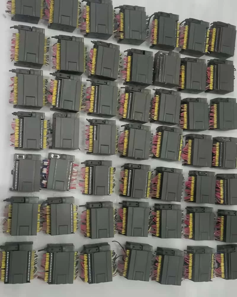
Longi Electromechanical has over 20 years of history, specializing in the field of industrial automation. With extensive experience in PLC (Programmable Logic Controller) applications, programming, unlocking, and repairs, our company boasts strong technical capabilities. Our experienced engineers and expert team efficiently and swiftly solve various issues encountered by customers in PLC applications.
Service Scope
We provide comprehensive PLC-related services covering major brands and applications across various industries.
Common PLC Brands and Models
Siemens: S7-200, S7-300, S7-400, S7-1200, S7-1500
Mitsubishi: FX Series, Q Series, L Series
Omron: CJ Series, CP Series, CS Series
Schneider: Modicon Series, M221, M241, M251
Delta: DVP Series, AS Series
Rockwell (AB): MicroLogix Series, CompactLogix Series, ControlLogix Series
Fuji: MICREX Series, SPH Series
Panasonic: FP Series
Industry Applications
Packaging Machinery
Printing Machinery
Injection Molding Equipment
CNC Machines
Chemical Processing Equipment
Food Processing Equipment
Wastewater Treatment Automation Systems
Constant Pressure Water Supply Systems
Automated Production Lines
Core Services
1. PLC Programming Services
Our engineers have extensive programming experience and can customize various automation control system solutions according to customer needs, offering comprehensive services from requirement analysis, system design, program development, to on-site commissioning.
Automation system design
New system development
Upgrading and retrofitting old systems
Program optimization
On-site commissioning and technical support
2. PLC Unlocking Services
Longi Electromechanical specializes in unlocking various PLC brands, quickly resolving issues caused by forgotten PLC passwords or system protection.
PLC password cracking and recovery
PLC program backup and recovery
Security unlocking technical consultation for various PLC brands
3. PLC Repair Services
We provide rapid diagnostic and repair services for various PLC brands, including both hardware and software repairs.
Repair of PLC mainboards and expansion modules
PLC communication fault troubleshooting
Diagnostic and repair of I/O modules
On-site emergency repairs and remote technical support
Why Choose Longi Electromechanical?
Over 20 years of experience in the PLC industry
Professional technical team and senior engineers
Rapid response to customer needs
Reliable technical support and after-sales service
Extensive experience covering various brands and industry applications
Choose Longi Electromechanical for professionalism and peace of mind!
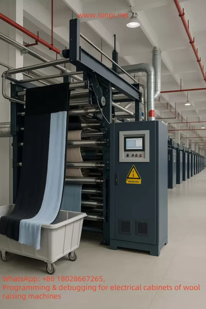
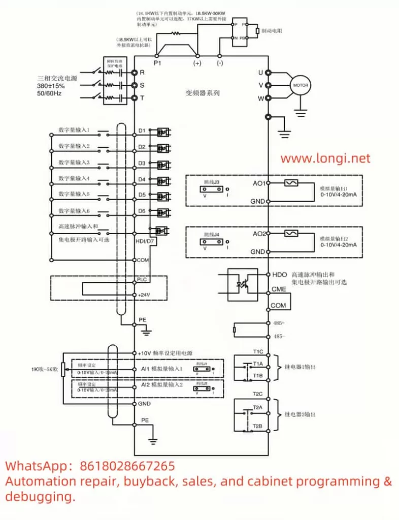
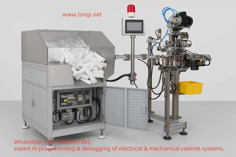
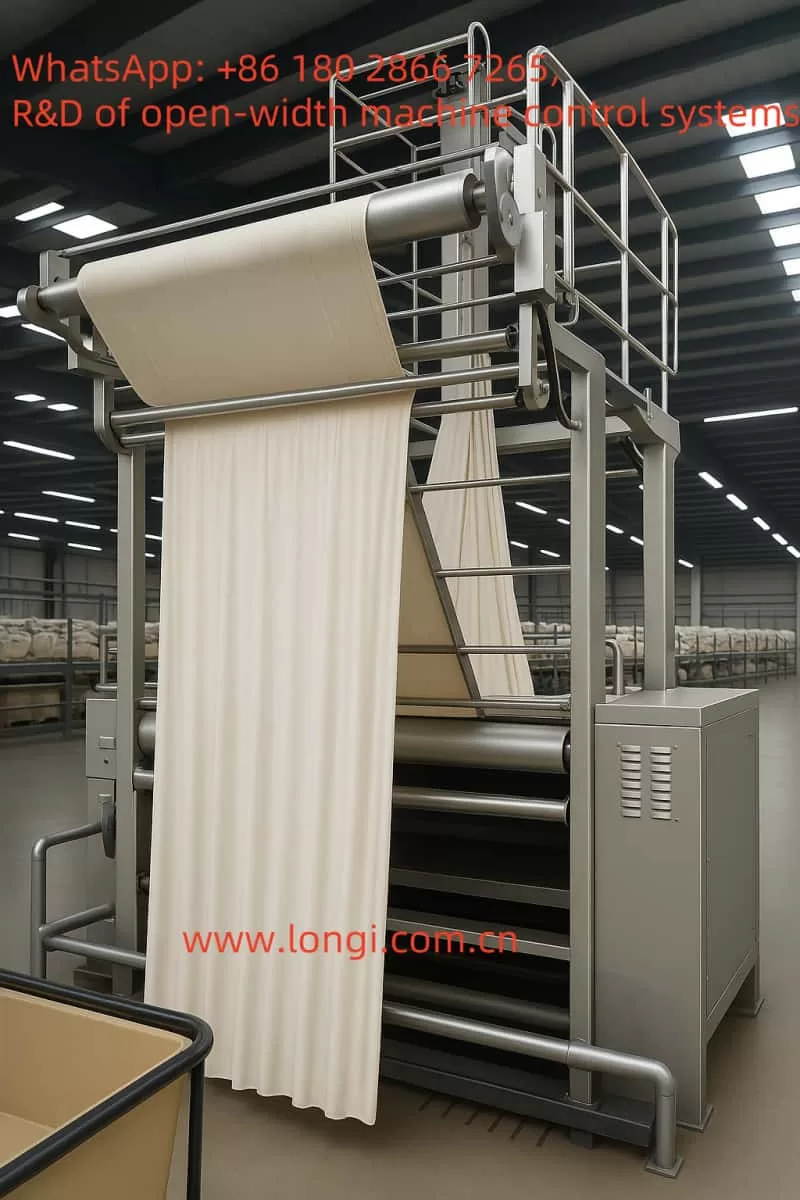
In the production process of textile factories, the napping machine (also known as the wire-drawing machine or yarn-extracting machine), as key equipment, undertakes the important tasks of stretching and homogenizing fibers. It is widely used in processes such as carding and yarn extraction. The Holip HLP-A100 inverter, as a general-purpose vector inverter, with its high reliability, wide range of applications, and rich control functions, can achieve precise control of the napping machine motor. This solution will comprehensively elaborate on the specific application of the Holip HLP-A100 inverter in the napping machine, covering the application positions, wiring methods, parameter settings, control logic, and providing descriptions of the electrical wiring diagram and control schematic. Additionally, equipment such as PLCs, touch screens, or industrial computers can be introduced according to requirements to achieve more advanced control functions.
I. Equipment Situation of the Napping Machine and Motor Function Analysis
The napping machine mainly stretches and homogenizes fibers through a series of rollers (or rolls). These rollers are usually driven by motors, and some roller groups may require independent motors to achieve precise speed control and ensure a constant drawing ratio (yarn-extracting ratio) of fibers between different rollers. The napping machine mainly includes the following key components and motor functions:
Main Stretching Roller Motor: Assumes the main stretching function and requires variable speed control to adapt to different fiber types and production requirements.
Auxiliary Roller Motor: Used for auxiliary stretching and fiber conveying, which may run synchronously with the main motor at a fixed speed ratio.
Conveying Motor: Responsible for conveying fibers from upstream equipment (such as carding machines) to the napping machine and conveying the processed fibers to downstream equipment (such as spinning machines).
Tension Control Motor: Some high-end napping machines are equipped with a dedicated tension control motor to maintain fiber tension and ensure production quality.
The motors of the napping machine are usually three-phase asynchronous motors with a power range of 1.5kW – 15kW, depending on the machine size and production capacity. This solution is based on the design of a main stretching roller motor with a power of 4kW.
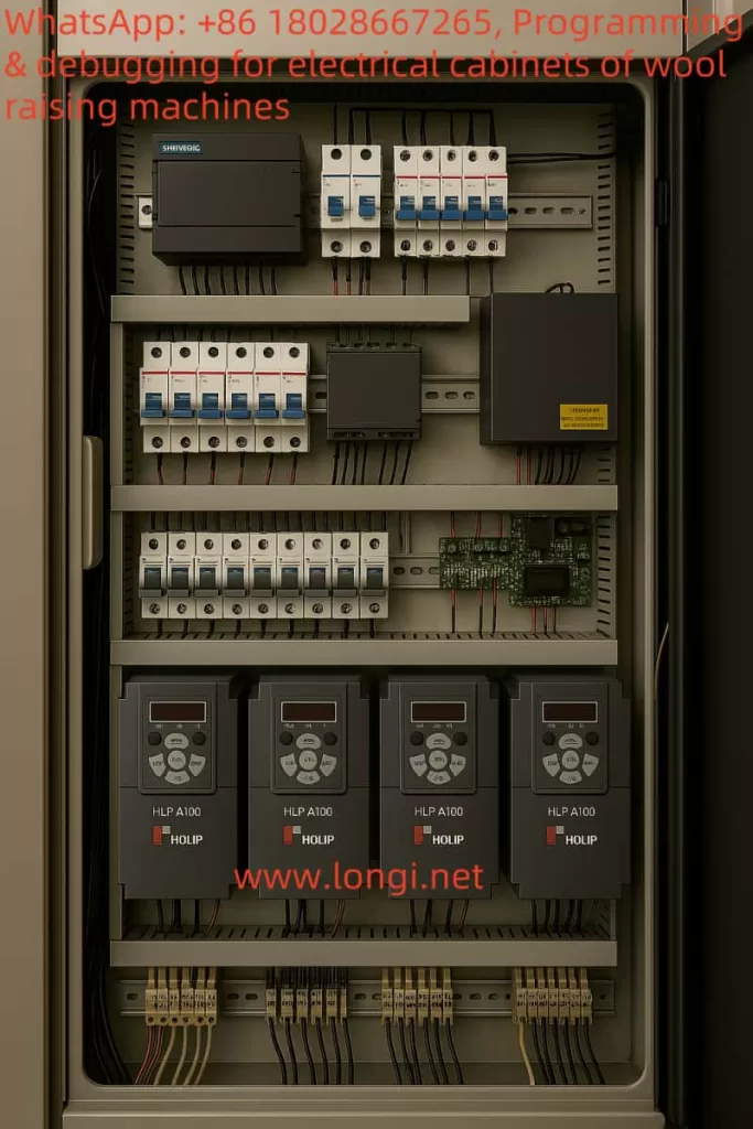
II. Key Features and Specifications of the Holip HLP-A100 Inverter
The Holip HLP-A100 inverter, as a general-purpose vector inverter, is suitable for various motor control needs in the industrial field. Below are its key features and specifications (based on the official manual):
Category
Details
Power Range
0.75kW – 220kW (models such as HLP-A100001143 to HLP-A100022043)
Voltage Range
Three-phase 380 – 440V/440 – 480V, 50/60Hz
Control Modes
Speed open loop, process closed loop, torque open loop
Digital Inputs/Outputs
4 digital inputs (DI1 – DI4), 2 digital outputs (DO1 – DO2), 2 relay outputs (KA – KB, FA – FB – FC)
Analog Inputs/Outputs
VI (0 – 10V/4 – 20mA), AI (0 – 10V/4 – 20mA), AO (0 – 20mA/4 – 20mA)
Maximum altitude 1000m (output power or temperature must be reduced when exceeding this limit)
This solution selects a model suitable for a 4kW motor from the HLP-A100 series, such as HLP-A100004043 (the specific model needs to be confirmed according to the manual).
III. Inverter Application Solution Design
3.1 Application Position
The Holip HLP-A100 inverter is mainly applied to the main stretching roller motor of the napping machine to achieve variable speed control of the main stretching roller. If the napping machine has multiple roller groups, multiple HLP-A100 inverters can be used, and cascade control can be implemented to achieve synchronous operation between different rollers and ensure a constant drawing ratio.
3.2 Wiring Method
3.2.1 Main Circuit Wiring
Main Circuit Terminals:
R, S, T: Connect to the three-phase AC power supply (380V/50Hz).
U, V, W: Connect to the motor output terminals.
PE: Grounding terminal, which must be connected to a reliable ground.
Brake Circuit (if required):
+UDC, -UDC: Connect to the brake resistor (the resistance value is selected according to the manual, usually 0.15 – 0.4Ω).
3.2.2 Control Circuit Wiring
Digital Inputs (DI):
DI1: Forward Run.
DI2: Stop.
DI3: Reverse Run (if required).
DI4: Other auxiliary functions (such as emergency stop).
Analog Inputs (AI):
AI1: Speed reference signal (e.g., provided by an external potentiometer or PLC).
Relay Outputs (Relay):
KA – KB: Fault alarm output.
FA – FB – FC: Running status indication.
Communication Interface (RS485):
RS+, RS-: Connect to the communication port of the PLC or touch screen.
3.2.3 Wiring Diagram Description
[Three-phase Power Supply] — R, S, T — [Holip HLP-A100 Inverter] — U, V, W — [Main Stretching Roller Motor] [Ground] — PE — [Holip HLP-A100 Inverter] [External Control Signal] — DI1(DI2/DI3/DI4) — [Holip HLP-A100 Inverter] [Speed Reference Signal] — AI1 — [Holip HLP-A100 Inverter] [Fault Alarm] — KA – KB — [Alarm Light or PLC] [Running Status] — FA – FB – FC — [Indicator Light or PLC] [Communication] — RS+, RS- — [PLC/Touch Screen]
3.3 Parameter Settings
Parameter settings are crucial for ensuring the normal operation of the inverter. Below are the typical parameter settings for the main stretching roller motor of the napping machine (based on the HLP-A100 manual):
3.3.1 Basic Parameters
C01. Configuration Parameters
C01.00 Configuration Mode: Set to “Speed Open Loop”.
C01.20 Motor Rated Power: Set to 4.0kW.
C01.21 Motor Rated Voltage: Set to 380V.
C01.22 Motor Rated Current: Set according to the manual or motor nameplate (e.g., 7.8A).
C01.23 Motor Rated Frequency: Set to 50Hz.
C01.24 Motor Slip: Set according to the motor parameters (usually 1% – 5%).
3.3.2 Reference and Ramp Parameters
C03. Reference/Ramp Parameters
C03.03 Maximum Reference: Set to 50.0Hz (or adjust according to actual requirements).
C03.04 Minimum Reference: Set to 0.5Hz (to avoid crawling at low speeds).
C03.05 Acceleration Time 1: Set to 5.0 seconds (adjust according to production requirements).
C03.06 Deceleration Time 1: Set to 5.0 seconds (adjust according to production requirements).
3.3.3 Digital Input/Output Parameters
C05. Digital Input/Output Parameters
C05.00 DI1 Function: Set to “Forward Run”.
C05.01 DI2 Function: Set to “Stop”.
C05.02 DI3 Function: Set to “Reverse Run” (if required).
C05.10 DO1 Function: Set to “Running Status”.
3.3.4 Analog Input/Output Parameters
C06. Analog Input/Output Parameters
C06.99 AI1 Function: Set to “Frequency Command”.
3.3.5 Cascade Control Parameters (if synchronous control is required)
C25. App. Functions Cascade Parameters
If multiple motors need to be synchronized, the main inverter can be set as the master, and the auxiliary inverters can be set as slaves, with the frequency ratio set.
3.4 Advanced Control Solution: Introducing PLC and Touch Screen
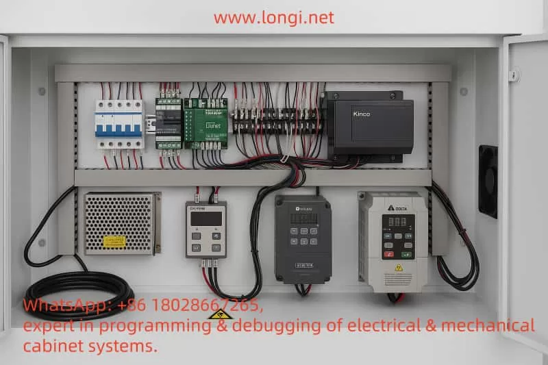
To achieve more advanced control and a user interface, a PLC and touch screen can be introduced. Below is the recommended solution:
3.4.1 PLC Selection
Select a PLC that supports the Modbus RTU protocol, such as the Siemens S7-200 series or Schneider Modicon series. The PLC is responsible for handling logic control, such as start, stop, speed setting, and fault handling.
3.4.2 Touch Screen Selection
Select a touch screen that supports Modbus RTU, such as the Weintek MT8071i series. The touch screen is used for the user interface, providing start/stop buttons, speed setting sliders, status displays, etc.
3.4.3 PLC and Touch Screen Wiring
The PLC is connected to the inverter via RS485 communication.
The touch screen is connected to the PLC’s communication port or directly to the inverter (if the touch screen supports direct control).
3.4.4 PLC Program Design
Use the PLC’s Modbus function blocks to read the inverter’s status (such as running status, output frequency).
Use the PLC’s Modbus function blocks to write control commands to the inverter (such as start, stop, frequency setting).
Logic can be added to the PLC program, such as:
When the start button is pressed, send the start command after checking safety conditions.
When the speed setting changes, update the inverter’s frequency command.
3.4.5 Touch Screen Design
Main Screen: Display the current speed, running status, and fault information.
Control Buttons: Start, stop, emergency stop.
Parameter Setting Page: Allow adjustment of acceleration/deceleration time, maximum/minimum frequency, etc.
IV. Control Schematic Description
Below is a description of the overall control schematic of the system:
The application of the Holip HLP-A100 inverter in the napping machine can significantly improve production efficiency and product quality. Through precise speed control and synchronization functions, it ensures the uniform stretching of fibers. Below are the key notes:
Model Selection: Select the appropriate inverter model according to the power of the napping machine motor.
Wiring: Ensure correct connection of the main circuit and control circuit, paying attention to grounding and shielding.
Parameter Settings: Adjust parameters such as acceleration/deceleration time and maximum/minimum frequency according to actual production requirements.
Safety Protection: Ensure that the emergency stop function works normally and comply with relevant safety standards.
Advanced Control: Achieve more flexible control and monitoring through PLC and touch screen.
Through the implementation of this solution, the efficient operation of the napping machine can be achieved, providing more reliable production assurance for textile factories.
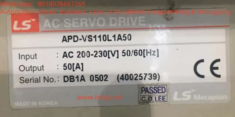
The KINGDA Electric Inverter A800 series is a powerful and flexible industrial automation device widely used in motor control and speed regulation. This article, based on its user manual and the provided fault code image (showing “EC.34 0.00”), details the operation panel functions, parameter initialization methods, password setting and removal, parameter access restriction settings, and the implementation of external terminal forward/reverse control and external potentiometer speed regulation. Additionally, for the situation where the EC.34 fault code is not explained in the manual, combined with feedback from the manufacturer’s technical staff, it analyzes its potential meaning and possible commercial operation background, and proposes solutions. The article is clearly structured and comprehensive, aiming to provide practical guidance for users.
I. Introduction to Operation Panel Functions and Parameter Management
Operation Panel Functions
The operation panel of the KINGDA Electric A800 series inverter is the core component for user interaction with the device. As seen from the fault image, the panel is equipped with a red LED display, currently showing “EC.34 0.00”, indicating the device is in a fault state. The functions of the buttons and knobs on the panel are as follows:
ESC (Exit): Exit the current menu or cancel the operation.
PROG (Programming): Enter parameter programming mode.
ENTER (Confirm): Confirm selection or enter the next level menu.
Direction Keys (Up, Down, Left, Right): Navigate menus or adjust parameter values.
STOP/RESET (Stop/Reset): Stop operation or reset faults.
RUN (Run): Start the inverter.
Knob: The central black knob is used to manually adjust parameters or scroll through menus.
These controls are intuitively designed for easy user operation. The user manual on page 24 (“Operation Panel and Status Parameters”) provides a detailed description.
Parameter Initialization Method
Parameter initialization is used to restore the inverter to factory settings, typically performed during first use or troubleshooting. The specific steps are as follows:
Press the PROG key to enter the main menu.
Use the direction keys to navigate to the “Parameter Initialization” option (see “Function Parameter Table” on page 28 of the manual).
Press ENTER to confirm; if a password is set, enter the password to unlock.
Select “Yes” and press ENTER to perform initialization; the device will automatically restart upon completion.
After initialization, all parameters are restored to default values, and the user needs to reconfigure them according to the application.
Password Setting and Removal
The password function protects parameters from unauthorized modification:
Setting a Password:
Enter the “Programmable Management Parameter Array” (page 90 of the manual).
Find the password setting item (usually parameter P10.XX).
Enter a 4-digit password and press ENTER to save.
Removing the Password:
If the password is remembered, it can be cleared by entering the correct password in the same menu.
If the password is forgotten, contact the manufacturer’s technical support and provide the serial number (e.g., “A800-250007G-AB00-250040G” on page 7 of the manual) to unlock.
Alternatively, clear the password through parameter initialization, but this will reset all settings.
Parameter Access Restriction Setting
Parameter access restrictions further enhance security:
Enter the “Programmable Management Parameter Array” (page 90).
Find the “Parameter Lock” or “Access Level” option (e.g., P10.01).
Set to “Lock Mode”, with options for “Read-Only” or “Fully Locked”.
After saving the settings, unlocked users cannot modify parameters.
These features ensure the security and stability of the device parameters.
II. External Terminal Forward/Reverse Control and External Potentiometer Speed Regulation
External Terminal Forward/Reverse Control
Controlling the inverter’s forward and reverse operation through external switches requires wiring and parameter settings:
Wiring:
Two-Wire Control (page 101 of the manual, “Two-Wire Switch Control for Inverter Forward and Reverse”):
Terminal FWD (Forward) connected to one end of the switch.
Terminal REV (Reverse) connected to the other switch.
COM terminal is the common ground.
Three-Wire Control (page 101, “Three-Wire Self-Resetting Switch Control”):
P02.01 (Start/Stop Control Source) set to “External Terminal Control”.
P02.02 (Direction Control Source) set to “Terminal FWD/REV” or “Three-Wire Control”.
P05.00 (Input Terminal Function Selection) assign functions to FWD, REV, or SB1/SB2/SB3.
External Potentiometer Speed Regulation
Adjusting the output frequency through an external potentiometer to achieve motor speed regulation:
Wiring (page 100 of the manual, “External Potentiometer Connection to Inverter”):
One end of the potentiometer connected to +10V (power), the other end to GND (ground).
The middle tap connected to VI (analog input).
Parameter Settings:
P00.06 (Main Frequency Reference Source) set to “VI Analog Input”.
P03.00 (Analog Input Range) set to 0-10V, corresponding to 0 to maximum frequency (P00.03).
Calibrate P03.01 (Minimum Input Voltage) and P03.02 (Maximum Input Voltage) to match the potentiometer.
After correct configuration, users can flexibly control the inverter through switches or the potentiometer.
III. Analysis of EC.34 Fault Code
Fault Phenomenon and Missing Manual Information
The inverter displays “EC.34 0.00” and cannot operate normally. Upon checking pages 92-121 of the user manual (“Fault Diagnosis and Solutions” to “Common EMC Interference Problem Rectification Suggestions”), no explanation for EC.34 is found. After consulting the manufacturer’s technical staff, the response was “need to contact the dealer to solve”, suggesting that EC.34 is not a standard fault code.
Speculation on Fault Meaning
Combining the feedback from technical staff and the fact that it is not mentioned in the manual, EC.34 may be a black-box operation code set by the dealer. The analysis is as follows:
Clock Function Association: The A800 series may have a built-in operation time limit mechanism (parameters may be hidden in the “Management Parameter Array” on pages 49-90), such as setting a 3-month operation cycle.
Artificial Shutdown: After the cycle ends, EC.34 is triggered, displaying a fault and shutting down, but the hardware is actually undamaged.
Commercial Purpose: This design may be set by the dealer to recover outstanding payments, promote services, or force users to pay additional fees, which is a malicious commercial practice.
This practice exists in certain market environments but lacks transparency and may harm user rights.
Solution Methods
Contact the Dealer:
Provide the serial number and purchase certificate, and request to lift the restriction.
Technical Unlocking:
Try parameter initialization (see Part One), which may reset the time limit but will clear all settings.
Legal Rights Protection:
If confirmed as malicious setting, keep evidence (manual, pictures, communication records) and complain to consumer protection agencies.
IV. Summary and Suggestions
The KINGDA Electric A800 series inverter has an intuitive operation panel, rich functions, supports parameter initialization, password protection, and external control, suitable for various industrial scenarios. However, the EC.34 fault reveals potential commercial traps. Users should:
Familiarize with the Manual: Master parameter settings and operation methods.
Backup Parameters: Prevent loss of configuration during initialization.
Choose Suppliers: Prioritize cooperation with reputable dealers.
Keep Certificates: Ensure after-sales rights.
When facing unclear faults like EC.34, prioritize negotiating with the dealer; if unsuccessful, seek technical support or legal channels. This case reminds users to be vigilant against technical black-box operations and calls for the industry to standardize commercial behavior to protect user interests.
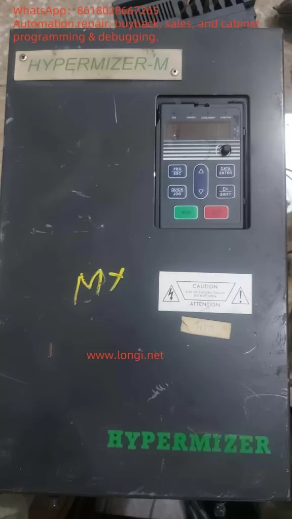
The operation panel of the HYPERMIZER-M RT4 series inverter provides various functions for parameter settings, status monitoring, and operational control. Below is an overview of the main functions of the operation panel:
Function Indicator Lights
RUN: Indicates the running status. The light is off when the inverter is stopped and on when it is running.
FWD/REV: Indicates forward or reverse operation. The light is off for forward operation and on for reverse operation.
LOCAL/REMOT: Indicates the control mode. The light is off for keypad control, on for terminal control, and flashing for remote communication control.
TUNE/TRIP: Indicates overload warning. The light is on for torque control mode, flashes slowly during self-learning, and flashes quickly during a fault.
Unit Indicator Lights
Hz: Frequency unit.
A: Current unit.
V: Voltage unit.
RPM: Speed unit.
%: Percentage.
Display Area
The 5-digit LED display shows the set frequency, output frequency, and other monitoring data, as well as alarm codes.
Keypad Buttons
PRG/ESC: Program key for entering or exiting the first-level menu.
DATA/ENTER: Confirmation key for entering the next menu level and confirming parameter settings.
△: Increment key for increasing data or function codes.
▽: Decrement key for decreasing data or function codes.
□: Shift key for cycling through display parameters in stop or run mode and selecting the modification position for parameters.
RUN: Run key for starting operation in keypad mode.
STOP/RST: Stop/Reset key for stopping operation or resetting from a fault.
QUICK/JOG: Multifunction key for switching functions based on P7-01 settings.
Setting and Removing Passwords
Setting a Password
Enter the function parameter mode and locate PP-00 (User Password).
Set a non-zero value as the user password.
Exit the function parameter mode; the password protection will be activated.
Removing a Password
Enter the function parameter mode and input the correct user password.
Locate PP-00 (User Password) and set it to 0.
Exit the function parameter mode; the password protection will be deactivated.
Setting Parameter Access Restrictions
Enter the function parameter mode and locate PP-04 (Function Code Modification Attribute).
Set to 0 for modifiable or 1 for non-modifiable.
Restoring Factory Default Settings
Enter the function parameter mode and locate PP-01 (Parameter Initialization).
Set to 01 to restore default values, excluding motor parameters.
Set to 02 to clear recorded information.
Forward/Reverse Control via Terminals and External Potentiometer Speed Control
Forward/Reverse Control via Terminals
Terminals: FWD (Forward), REV (Reverse).
Parameter Settings: Set P4-00 (D1 Terminal Function Selection) to 1 (Forward Operation) or 2 (Reverse Operation).
External Potentiometer Speed Control
Terminals: AI1 (Analog Input Terminal 1).
Parameter Settings: Set P0-03 (Main Frequency Source A Selection) to 4 (Panel Potentiometer Setting).
Fault Codes and Handling
Fault Codes
01: Overcurrent fault.
02: Undervoltage fault.
03: Overvoltage fault.
04: Overheating fault.
05: Phase loss fault.
06: Overload fault.
07: Short circuit fault.
08: Communication fault.
09: Encoder fault.
10: Parameter read/write fault.
Fault Handling
Overcurrent Fault: Check if the motor and load are normal; ensure the motor is not overloaded.
Undervoltage Fault: Check if the input voltage is normal; ensure the voltage is within the allowed range.
Overvoltage Fault: Check if the input voltage is too high; ensure the voltage is within the allowed range.
Overheating Fault: Check if the inverter’s cooling is normal; ensure the cooling fan is working properly.
Phase Loss Fault: Check if the input power supply has a phase loss; ensure the power supply is normal.
Overload Fault: Check if the motor and load are overloaded; ensure the load is within the allowed range.
Short Circuit Fault: Check if the motor and load are short-circuited; ensure the circuit is normal.
Communication Fault: Check if the communication lines are normal; ensure the communication equipment is working properly.
Encoder Fault: Check if the encoder is working properly; ensure the encoder signal is normal.
Parameter Read/Write Fault: Check if the parameter settings are correct; ensure the parameters are within the allowed range.
Conclusion
The user manual for the HYPERMIZER-M RT4 series inverter provides detailed operational guidance and fault handling methods, helping users correctly operate and maintain the inverter. By understanding the operation panel functions, setting passwords and parameter access restrictions, restoring factory default settings, implementing forward/reverse control via terminals, and external potentiometer speed control, as well as identifying and handling common faults, users can better utilize the inverter’s capabilities, improving work efficiency and extending the equipment’s lifespan.
This document aims to design a detailed application scheme based on the Kinco CV20 inverter for the PE pipe packaging and pipe arranging machine (winding machine). The scheme covers motor function analysis, inverter selection, wiring methods, parameter settings, and control system integration. The pipe arranging machine uses a winding mechanism to evenly wrap PE pipes onto a reel, requiring precise control of winding speed and tension. The CV20 inverter, with its variable frequency speed regulation and communication capabilities, can meet the requirements of multi-motor coordinated control.
II. Motor Function Analysis for the Pipe Arranging Machine
Main Winding Motor
Function: Drives the winding mechanism to control the winding speed and tension of the PE pipe.
Function: Drives the conduit device to move horizontally, ensuring even distribution of the pipes.
Parameters: Three-phase motor (or single-phase), 380V/0.75kW.
Auxiliary Motor
Function: Such as driving a conveyor belt, with low power and no need for inverter control.
Application Positioning: The CV20 inverter is mainly used for speed regulation and synchronous control of the main winding motor and lateral movement motor.
III. CV20 Inverter Selection
Motor Type
Model
Applicable Scenario
Main Winding Motor (2.2kW)
CV20-4T-0022G
Three-phase 380V input/output
Lateral Movement Motor (0.75kW)
CV20-4T-0007G
Three-phase 380V input/output
Lateral Movement Motor (Single-phase)
CV20-2S-0007G
Single-phase 220V input/output (optional)
Key Features:
Output Frequency: 0-300Hz, supports V/F control and automatic torque boost.
Communication Interface: Built-in Modbus RS485, compatible with PLC integration.
Environmental Adaptability: Temperature -10℃~50℃, humidity 5%~95%RH.
IV. Wiring Methods
1. Main Circuit Wiring
Power Input: Three-phase 380V AC → Circuit Breaker → Inverter R/L1, S/L2, T/L3 (PE grounded).
Motor Output: Inverter U/T1, V/T2, W/T3 → Motor U, V, W.
2. Control Circuit Wiring
Control Methods:
Keyboard Control: Directly set frequency and start/stop.
Terminal Control:
X1: Start/Stop
X2: Forward/Reverse (Lateral Movement)
X3: Emergency Stop
AI1: Analog Frequency Input
Communication Control: RS485 interface (+5V, 485+, 485-, GND) connected to PLC/HMI.
HMI: Recommend Siemens KTP400 or Omron NB5W, for parameter setting and status monitoring.
Communication Configuration:
Inverter P51: Modbus-RTU protocol
Baud Rate P52: 9600bps
Control Architecture:复制代码PLC ----> [RS485] ----> CV20-4T-0022G ----> Main Winding Motor | |----> [RS485] ----> CV20-4T-0007G ----> Lateral Movement Motor | |----> HMI (display status, set parameters)
VII. Function Realization
Main Winding Motor:
Speed Control: Achieve multi-level winding speeds through frequency adjustment.
Reciprocating Motion: Automatic direction switching using triangle wave frequency mode.
Synchronous Control: PLC reads the main motor frequency and dynamically adjusts the lateral speed.
VIII. Safety and Protection Measures
Grounding Protection: PE terminal reliably grounded, grounding wire ≥3.5mm².
Overcurrent Protection: Main circuit equipped with circuit breakers/fuses.
Emergency Stop Function: X3 terminal connected to emergency stop button.
Voltage Protection: Inverter built-in overvoltage/undervoltage alarm.
IX. Conclusion
The Kinco CV20 inverter can efficiently control the main winding and lateral movement motors of the PE pipe arranging machine through flexible wiring methods, parameter configuration, and communication functions. It is recommended to build an automated system in combination with PLC and HMI, with specific model selection referring to Siemens or Omron products. Users need to further optimize settings based on actual equipment parameters and follow the manufacturer’s safety specifications.
Note: This scheme is a general design, and parameters and wiring may need to be adjusted in actual applications based on equipment manuals and site conditions.
This scheme aims to apply the Lianchuang High-Tech LC400E inverter to the unwinding and slitting machine. By precisely controlling the motor speed and torque, it achieves automation and efficient operation of core functions such as unwinding, cutting, and rewinding. The scheme covers motor function analysis, wiring methods, parameter settings, function realization, and auxiliary equipment selection to ensure the efficiency and stability of the unwinding and slitting machine’s production.
II. Analysis of the Unwinding and Slitting Machine Structure and Motor Configuration
Equipment Functions The unwinding and slitting machine is used to cut wide rolls of materials into multiple narrow rolls. Its core functions include unwinding, cutting, and rewinding.
Motor Configuration
Unwinding Motor: Controls the unwinding speed of the parent roll and requires constant tension to prevent material slack or breakage.
Rewinding Motor: Controls the winding of narrow materials and requires tension adjustment according to the roll diameter (trapezoidal tension).
Cutting Motor: Drives the cutting components and requires precise speed control.
Control Requirements Tension control is the core requirement. It needs to achieve constant tension during unwinding and trapezoidal tension during rewinding through motor torque control.
III. Key Features of the LC400E Inverter
High-Performance Vector Control: Supports precise speed and torque control to meet tension synchronization requirements.
Multi-Mode Control: Terminal control, analog input, and multi-speed settings to adapt to different working conditions.
Safety Protection: Functions such as overvoltage, overcurrent, and motor protection ensure equipment safety.
Communication Capabilities: Supports Modbus communication (RS232/RS485) for easy integration with PLC/HMI.
Adjustable Parameters: Acceleration/deceleration time, PID control, and other parameters can be flexibly adjusted.
Specifications: Power range from 0.75 kW to 500 kW, with output current reaching 63 A for models like G022/T4, suitable for the motor requirements of the unwinding and slitting machine.
IV. Application Positions of the LC400E in the Unwinding and Slitting Machine
Unwinding Motor: Torque control mode to maintain constant tension.
Rewinding Motor: Speed/torque control mode to support trapezoidal tension adjustment.
Cutting Motor: Speed control mode to ensure cutting accuracy. Application Suggestions: Configure multiple inverters according to the number of motors, such as one for the unwinding motor and one for the rewinding motor.
V. Wiring Methods
Main Circuit Wiring
Connect the input terminals (R, S, T) to the three-phase power supply and the output terminals (U, V, W) to the motor. Connect the PE terminal to the ground.
Refer to the LC400E manual for wire size specifications (e.g., for a 22 kW model, the input is 100 A, and the output is 63 A).
Safety Protection: Install an emergency stop button and set inverter protection parameters.
Tension Control: Prioritize the installation of tension sensors to ensure control accuracy.
Multi-Motor Synchronization: Coordinate through the PLC to avoid uneven tension.
Environmental Requirements: Install the inverter in a well-ventilated and dry environment, away from dust and moisture.
X. Summary
This scheme achieves high-precision speed and tension control through the application of the LC400E inverter in the unwinding and slitting machine, combined with PLC and HMI for automated operation. Key measures include:
Adopting constant tension and trapezoidal tension control for the unwinding and rewinding motors, respectively.
Using standard wiring methods and key parameter settings to ensure system stability.
Selecting Siemens/Mitsubishi equipment to achieve efficient automated control. This scheme can significantly improve the production efficiency of the unwinding and slitting machine, reduce operation difficulty and fault risks, and is suitable for the roll material processing industry.
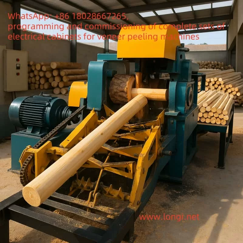
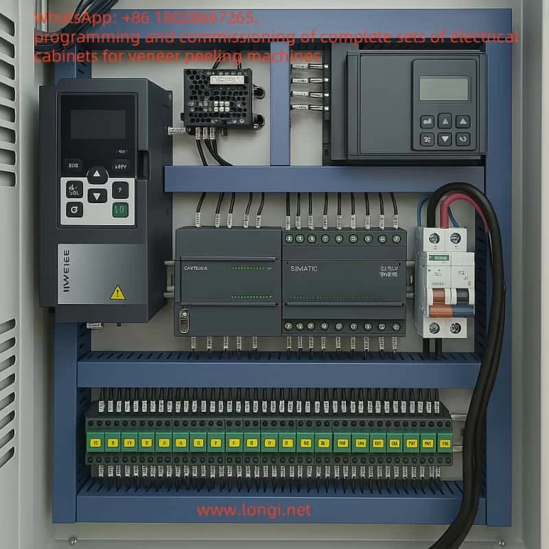
The rotary cutting machine is an essential piece of equipment in the woodworking industry, primarily used to peel logs into thin veneer sheets, which are widely applied in the production of plywood, furniture, and decorative materials. To achieve efficient and precise processing, the rotary cutting machine relies on the coordinated operation of multiple motors, including the main spindle motor for log rotation, the cutting blade motor for veneer cutting, the conveyor belt motor for veneer output, and the feed motor for controlling cutting thickness. These motors require precise speed and torque control to ensure processing quality and production efficiency. As a versatile electrical device capable of flexibly controlling motor operation, the inverter plays a critical role in the rotary cutting machine.
This article provides a detailed explanation of how to apply the Mobeck MT110 inverter to various motor control aspects of a rotary cutting machine, covering functional analysis, inverter selection, wiring design, parameter settings, and the integration of PLC and touchscreen systems. Through a well-designed and implemented solution, the rotary cutting machine can achieve efficient, stable, and automated operation, meeting the demands of modern woodworking processes.
Functional Analysis of the Rotary Cutting Machine
The primary task of a rotary cutting machine is to process logs into veneer sheets, involving log fixation and rotation, cutting by the blade, veneer output, and precise control of cutting thickness. Below is a detailed analysis of the main motor functions in a rotary cutting machine:
1. Main Spindle Motor (Rotation Function)
Function: The main spindle motor drives the log to rotate, serving as the core power component of the rotary cutting machine.
Characteristics: It requires high power, typically ranging from 5.5 kW to 15 kW (depending on the machine size), and needs stable speed output while allowing dynamic speed adjustments based on processing requirements.
Control Requirements: The inverter must support vector control mode to ensure high torque output at low speeds and be capable of receiving external speed reference signals (e.g., from a PLC or potentiometer).
2. Cutting Blade Motor (Cutting Function)
Function: This motor drives the cutting blade to peel the rotating log into veneer sheets.
Characteristics: The power typically ranges from 3 kW to 7.5 kW, with speed adjustments required based on veneer thickness, and stable torque support during cutting.
Control Requirements: The inverter needs fast start/stop capabilities and precise speed control, often requiring synchronization with the main spindle motor.
3. Conveyor Belt Motor (Conveying Function)
Function: It ensures the smooth output of cut veneer sheets, maintaining production continuity.
Characteristics: The power is relatively low, typically between 0.75 kW and 2.2 kW, with speed needing to match the cutting rhythm.
Control Requirements: The inverter should support simple speed regulation and may need to operate in coordination with the cutting blade motor.
4. Feed Motor (Feed Function)
Function: It controls the feed speed of the cutting blade or log, directly determining the veneer thickness.
Characteristics: The power is low (0.75 kW to 1.5 kW), and it can be either an asynchronous motor or a servo motor, requiring high-precision speed control.
Control Requirements: If using an asynchronous motor, the inverter must support high-precision speed regulation and accept external analog signal inputs; if using a servo motor, a dedicated servo drive is required.
5. Other Auxiliary Motors
Function: These include motors for clamping devices, chip removal fans, etc., used to assist the processing operation.
Characteristics: The power is low (0.37 kW to 1.5 kW), with simple control requirements, typically needing only basic start/stop functions.
From the above analysis, it is clear that the motor control requirements of a rotary cutting machine are diverse. The main spindle and cutting blade motors demand high-performance control, while the conveyor belt and feed motors prioritize speed stability and precision. The Mobeck MT110 inverter, with its flexible control modes and rich functionality, is an ideal choice to meet these requirements.
Application Scheme of Mobeck MT110 Inverter
1. Inverter Application Positions
Based on the functional characteristics of the rotary cutting machine, the Mobeck MT110 inverter can be applied to the following key motor positions:
Main Spindle Motor: Use the MT110 inverter for vector control to ensure stable log rotation.
Cutting Blade Motor: Use the MT110 inverter for speed control, synchronized with the main spindle motor.
Conveyor Belt Motor: Use the MT110 inverter for simple speed regulation.
Feed Motor: If an asynchronous motor is used, the MT110 inverter can provide high-precision speed control; if a servo motor is used, a separate servo drive is required.
2. Inverter Selection
Assuming a medium-sized rotary cutting machine with the following motor power configuration:
Main Spindle Motor: 7.5 kW
Cutting Blade Motor: 5.5 kW
Conveyor Belt Motor: 1.5 kW
Feed Motor: 1.1 kW (asynchronous motor)
Based on the motor power and load characteristics, the following Mobeck MT110 inverter models are selected:
Main Spindle Motor: MT110-7.5kW (rated power 7.5 kW, 380V three-phase)
Cutting Blade Motor: MT110-5.5kW (rated power 5.5 kW, 380V three-phase)
Conveyor Belt Motor: MT110-1.5kW (rated power 1.5 kW, 380V three-phase)
Feed Motor: MT110-1.1kW (rated power 1.1 kW, 380V three-phase)
When selecting the inverter, ensure that its rated capacity is slightly higher than the motor power to provide a margin for potential overload conditions.
3. Wiring Design
The following uses the main spindle motor (7.5 kW) MT110 inverter as an example to detail the wiring method. The wiring for other motors is similar, with adjustments based on power and control requirements.
(1) Main Circuit Wiring
Power Input: Connect the three-phase 380V power supply to the inverter’s R, S, and T terminals.
Motor Output: Connect the inverter’s U, V, and W terminals to the three-phase input of the main spindle motor.
Grounding: Connect the inverter’s grounding terminal and the motor’s grounding terminal to the ground wire to ensure electrical safety.
Main Circuit Wiring Diagram (Text Description):
Power Supply (380V Three-Phase)
  L1 ---- R
  L2 ---- S
  L3 ---- T
         |
         |---- Ground Terminal ---- Ground
         |
  U ---- Motor U Phase
  V ---- Motor V Phase
  W ---- Motor W Phase
         |
         |---- Motor Ground Terminal ---- Ground
(2) Control Circuit Wiring
The control terminals of the MT110 inverter include digital inputs (DI), analog inputs (AI), and relay outputs (RO). Using the main spindle motor control as an example:
Start/Stop Control:
DI1 (Forward Start): Connect to the PLC output point (e.g., Y0) to control inverter start via the PLC.
DI2 (Stop): Connect to the PLC output point (e.g., Y1) to control inverter stop via the PLC.
COM: Common terminal, connected to the PLC’s common terminal.
Speed Reference:
AI1 (Analog Input): Connect to the PLC’s analog output module (0-10V signal) for speed regulation.
GND: Analog ground, connected to the PLC’s analog ground.
Fault Output:
RO1A/RO1B (Relay Output): Connect to the PLC input point (e.g., X0) to detect inverter faults.
Control Circuit Wiring Diagram (Text Description):
Using the main spindle motor (7.5 kW) MT110 inverter as an example, the key parameter settings are listed below. Assuming the MT110 inverter’s parameter numbering is similar to that of a general-purpose inverter, the settings are as follows:
P0.03 (Control Mode): Set to 1 (Vector Control without PG), suitable for the high torque requirements of the main spindle motor.
P0.04 (Run Command Source): Set to 1 (Terminal Control), using DI1/DI2 for start/stop control.
P0.06 (Frequency Reference Source): Set to 2 (AI1 Analog Input), using the PLC’s 0-10V signal to set the speed.
P1.00 (Motor Rated Power): Set to 7.5 (7.5 kW).
P1.01 (Motor Rated Voltage): Set to 380 (380V).
P1.02 (Motor Rated Frequency): Set to 50 (50 Hz).
P1.03 (Motor Rated Speed): Set to 1460 (assuming a 4-pole motor, approximately 1460 rpm at 50 Hz).
P2.00 (Acceleration Time): Set to 5 (5 seconds) to avoid startup shock.
P2.01 (Deceleration Time): Set to 5 (5 seconds) to ensure smooth stopping.
P5.00 (DI1 Function): Set to 1 (Forward Run).
P5.01 (DI2 Function): Set to 2 (Stop).
P6.00 (Relay Output Function): Set to 1 (Fault Output).
Parameter settings for other motors should be adjusted based on their specific functions:
Cutting Blade Motor: Set acceleration/deceleration time to 3 seconds to accommodate fast start/stop requirements.
Conveyor Belt Motor: Use V/F control (P0.03=0) to simplify control logic.
Feed Motor: Requires high-precision speed control, so adjust the gain and offset parameters of AI1 (e.g., P4 group parameters).
Parameter Settings Example Table:
Parameter No.
Description
Main Spindle Motor
Cutting Blade Motor
Conveyor Belt Motor
Feed Motor
P0.03
Control Mode
1 (Vector)
1 (Vector)
0 (V/F)
1 (Vector)
P0.04
Run Command Source
1 (Terminal)
1 (Terminal)
1 (Terminal)
1 (Terminal)
P0.06
Frequency Reference Source
2 (AI1)
2 (AI1)
2 (AI1)
2 (AI1)
P1.00
Motor Rated Power (kW)
7.5
5.5
1.5
1.1
P2.00
Acceleration Time (s)
5
3
2
2
P2.01
Deceleration Time (s)
5
3
2
2
5. PLC and Touchscreen Selection and Application
(1) Selection
To achieve automated control of the rotary cutting machine, a PLC and touchscreen are required:
PLC: Recommend the Siemens S7-200 SMART series (e.g., CPU 224XP), which supports analog input/output and offers strong scalability.
Touchscreen: Recommend the Siemens KTP400 Basic (7-inch), which supports communication with the PLC via Profinet and provides an intuitive operation interface.
(2) PLC Program Design
The PLC is responsible for coordinating the operation of each motor, with the main functions including:
Start/Stop Control: Use PLC output points (e.g., Y0, Y1) to control the DI1/DI2 of each inverter, enabling motor start/stop.
Speed Regulation: Use the PLC’s analog output module (0-10V) to control the inverter’s AI1, dynamically adjusting each motor’s speed.
Synchronization Control: Calculate the speed ratio between the main spindle motor and the cutting blade motor through the program to ensure consistent cutting thickness.
Fault Detection: Use the inverter’s relay output (RO1A/RO1B) to send fault signals to the PLC input point (e.g., X0), triggering an alarm.
VAR
    Start_Main : BOOL;        // Main Spindle Motor Start Signal
    Stop_Main : BOOL;         // Main Spindle Motor Stop Signal
    Speed_Main : REAL;        // Main Spindle Motor Speed (0-10V)
    Start_Feed : BOOL;        // Feed Motor Start Signal
    Stop_Feed : BOOL;         // Feed Motor Stop Signal
    Speed_Feed : REAL;        // Feed Motor Speed (0-10V)
    Start_Conveyor : BOOL;    // Conveyor Belt Motor Start Signal
    Stop_Conveyor : BOOL;     // Conveyor Belt Motor Stop Signal
    Speed_Conveyor : REAL;    // Conveyor Belt Motor Speed (0-10V)
END_VAR

// Main Spindle Motor Control
IF Start_Main AND NOT Stop_Main THEN
    Inverter_Main.CommandWord := 16#83; // Run Forward
    Inverter_Main.FrequencyReference := Speed_Main * 5; // 0-10V corresponds to 0-50Hz
ELSE IF Stop_Main THEN
    Inverter_Main.CommandWord := 16#80; // Stop
END_IF

// Feed Motor Control
IF Main_Spindle_At_Speed AND Start_Feed AND NOT Stop_Feed THEN
    Inverter_Feed.CommandWord := 16#83;
    Inverter_Feed.FrequencyReference := Speed_Feed * 5;
ELSE IF Stop_Feed THEN
    Inverter_Feed.CommandWord := 16#80;
END_IF

// Conveyor Belt Motor Control
IF Cutting_In_Progress AND Start_Conveyor AND NOT Stop_Conveyor THEN
    Inverter_Conveyor.CommandWord := 16#83;
    Inverter_Conveyor.FrequencyReference := Speed_Conveyor * 5;
ELSE IF Stop_Conveyor THEN
    Inverter_Conveyor.CommandWord := 16#80;
END_IF
(3) Touchscreen Interface Design
The touchscreen is used for parameter settings and operation status monitoring, with the main interfaces including:
Main Interface: Displays the operation status (running/stopped), current speed (Hz), and fault status of each motor.
Parameter Setting Interface: Sets the target speed of each motor (via PLC AO output) and veneer thickness (via feed motor speed adjustment).
Alarm Interface: Displays inverter fault information (e.g., overload, overheating) and provides a reset button.
6. Safety Considerations
To ensure the safe operation of the equipment, the following precautions should be observed:
Electrical Safety: Ensure reliable grounding of the inverter and motor to prevent electrical leakage risks.
Operational Safety: Set an emergency stop button on the touchscreen, allowing the PLC to stop all inverters simultaneously.
Overload Protection: Enable overload protection in the inverter parameters (e.g., P9 group parameters) to prevent motor overheating.
Maintenance Safety: Regularly inspect the inverter’s cooling fan and wiring terminals to ensure long-term operational stability.
Conclusion
Through the above scheme, the Mobeck MT110 inverter can fully meet the control requirements of a rotary cutting machine:
Main Spindle Motor: Achieves smooth log rotation with adjustable speed, ensuring processing continuity.
Cutting Blade Motor: Operates synchronously with the main spindle motor, ensuring cutting quality.
Conveyor Belt Motor: Provides stable veneer output, with speed matching the cutting rhythm.
PLC and Touchscreen: Enable automated control and human-machine interaction, enhancing equipment efficiency and ease of operation.
The advantages of this scheme lie in its modular design and flexibility, allowing users to adjust motor power, inverter models, and control parameters based on actual needs. Additionally, the integration of a PLC and touchscreen enables the rotary cutting machine to achieve a higher level of automation, significantly improving production efficiency and product quality.