Key Points:
- FAULT 008, known as “Heatsink Over Temperature,” indicates that the inverter’s heatsink temperature has exceeded safe limits, likely to protect the device from overheating damage.
- Common causes include blocked or dirty heatsink fins, high ambient temperatures, or cooling fan failure.
- Troubleshooting involves cleaning the heatsink, verifying ambient temperature, and checking fan operation.
- Preventive measures include regular maintenance, temperature monitoring, and proper installation to ensure adequate airflow.
What is FAULT 008?
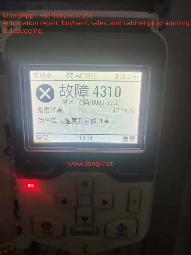
When a Rockwell PowerFlex 400 series inverter displays FAULT 008, labeled “Heatsink OvrTmp,” it signals that the heatsink temperature has surpassed its safe operating threshold. This fault halts the inverter to prevent damage to internal components, such as the power electronics. The control panel will show “FAULT 008 Heatsink Ovrtmp” with a yellow or orange indicator light, alerting the user to take immediate action.

Why Does It Happen?
The overheating of the heatsink can stem from several issues:
- Blocked or Dirty Heatsink Fins: Dust or debris accumulation reduces the heatsink’s ability to dissipate heat.
- High Ambient Temperature: Operating environments exceeding 40°C (104°F) for IP 30/NEMA 1/UL Type 1 installations or 50°C (122°F) for open-type installations can overwhelm the cooling system.
- Fan Failure: A malfunctioning or stopped cooling fan disrupts airflow, causing heat buildup.
How to Address It?
To resolve FAULT 008, follow these steps:
- Clean the Heatsink: Power off the inverter, open the enclosure, and use compressed air or a soft brush to remove dust or debris from the heatsink fins.
- Check Ambient Temperature: Measure the surrounding temperature to ensure it is within the specified limits. If too high, improve ventilation or relocate the inverter.
- Inspect the Fan: Verify that the cooling fan is operational. Replace it if it’s not functioning, using a compatible part.
Preventing Future Issues
Regular maintenance, such as cleaning the heatsink and monitoring ambient conditions, along with proper installation to ensure good airflow, can help avoid this fault in the future.
Comprehensive Analysis and Solutions for FAULT 008 in Rockwell PowerFlex 400 Series Inverters
Introduction
The Rockwell PowerFlex 400 series inverters are widely used in industrial automation for controlling AC motor speed and torque, particularly in applications like fans and pumps. Known for their reliability and versatility, these inverters occasionally encounter faults that require prompt attention. One such fault, FAULT 008 (Heatsink Over Temperature), indicates that the inverter’s heatsink has exceeded its safe temperature threshold. This article provides a detailed exploration of FAULT 008, including its definition, causes, troubleshooting steps, solutions, and preventive measures to ensure reliable operation.
This content is based on information from the Rockwell PowerFlex 400 User Manual and fault code documentation, ensuring accuracy and relevance for users addressing this issue.
1. Understanding FAULT 008
FAULT 008, labeled “Heatsink OvrTmp,” is a critical fault in the PowerFlex 400 series that occurs when the heatsink temperature exceeds the safe operating limit. The heatsink is a vital component responsible for dissipating heat generated by the inverter’s power electronics, such as IGBT modules. When this fault is triggered, the inverter halts operation to prevent thermal damage, displaying “FAULT 008 Heatsink Ovrtmp” on the control panel with a yellow or orange indicator light. This fault is classified as an Auto-Reset/Run type, meaning it may attempt to reset automatically if configured (via parameters A092 and A093), provided the underlying issue is resolved.
2. Causes of FAULT 008
Several factors can lead to the heatsink overheating, triggering FAULT 008. The primary causes include:
2.1 Blocked or Dirty Heatsink Fins
The heatsink relies on air circulation to dissipate heat. Dust, oil, or debris accumulation on the fins can obstruct airflow, significantly reducing cooling efficiency. This is particularly common in dusty industrial environments.
2.2 High Ambient Temperature
The PowerFlex 400 has specific environmental temperature limits:
- IP 30/NEMA 1/UL Type 1 Installations: Maximum ambient temperature of 40°C (104°F).
- Open-Type Installations: Maximum ambient temperature of 50°C (122°F).
If the operating environment exceeds these limits, the heatsink may struggle to maintain safe temperatures.
2.3 Cooling Fan Failure
The inverter’s cooling fan ensures adequate airflow over the heatsink. A malfunctioning fan—due to mechanical issues (e.g., worn bearings), electrical faults, or blockages—can lead to insufficient cooling and overheating.
2.4 Excessive Load or Duty Cycle
Running the inverter at or beyond its rated capacity for extended periods generates excessive heat, which the cooling system may not handle effectively.
2.5 Poor Ventilation
Improper installation, such as placing the inverter in a confined space or obstructing air inlets/outlets, can trap heat and cause the heatsink to overheat.
| Cause | Description | Impact |
|---|---|---|
| Blocked Heatsink Fins | Dust or debris reduces airflow, impairing heat dissipation. | Heatsink temperature rises. |
| High Ambient Temperature | Environment exceeds 40°C (IP 30) or 50°C (Open type). | Cooling system overwhelmed. |
| Cooling Fan Failure | Fan stops or operates inefficiently, reducing airflow. | Inadequate heatsink cooling. |
| Excessive Load | Prolonged high-load operation generates excessive heat. | Heatsink temperature exceeds limits. |
| Poor Ventilation | Restricted airflow due to improper installation or obstructions. | Heat accumulation. |

3. Troubleshooting FAULT 008
Resolving FAULT 008 requires a systematic approach to identify and address the root cause. Below are the recommended steps:
3.1 Inspect and Clean Heatsink Fins
- Procedure: Disconnect the inverter from power, open the enclosure, and inspect the heatsink fins for dust, oil, or debris.
- Tools: Use compressed air or a soft brush to clean the fins, ensuring no contaminants remain.
- Precautions: Avoid introducing foreign objects into the inverter during cleaning.
3.2 Verify Ambient Temperature
- Procedure: Measure the ambient temperature around the inverter using a thermometer.
- Standards:
- IP 30/NEMA 1/UL Type 1: ≤40°C (104°F).
- Open Type: ≤50°C (122°F).
- Action: If the temperature exceeds limits, enhance ventilation (e.g., add fans or air conditioning) or relocate the inverter to a cooler area.
3.3 Check Cooling Fan Operation
- Procedure:
- Power on the inverter and confirm the fan is running by listening for operation or checking for airflow.
- Inspect for blockages or damage to the fan blades.
- Listen for unusual noises indicating bearing wear or mechanical issues.
- Action: Replace a faulty fan with a genuine Rockwell part, following the manual’s replacement instructions.
3.4 Evaluate Load and Duty Cycle
- Procedure:
- Check the inverter’s load to ensure it does not exceed the rated capacity.
- Review parameter A089 [Current Limit 1] to confirm it matches the motor’s specifications.
- Action: Reduce the load or adjust parameters if overloading is detected. Consider upgrading to a higher-capacity inverter if necessary.
3.5 Ensure Adequate Ventilation
- Procedure:
- Verify that the inverter has sufficient clearance (at least 10-15 cm) around air inlets and outlets.
- Check for obstructions blocking airflow.
- Action: Reposition the inverter or remove obstructions to improve ventilation.
4. Solutions and Preventive Measures
4.1 Solutions
Based on the troubleshooting results, apply the following solutions:
- Dirty Heatsink Fins: Clean thoroughly to restore airflow.
- High Ambient Temperature: Install cooling equipment or relocate the inverter.
- Fan Failure: Replace the fan with a compatible part.
- Excessive Load: Adjust load or parameters, or upgrade the inverter.
- Poor Ventilation: Reconfigure the installation to ensure proper airflow.
4.2 Preventive Measures
To minimize the risk of FAULT 008 recurring, adopt these practices:
- Regular Maintenance:
- Clean heatsink fins and inspect fans every 3-6 months, adjusting frequency based on environmental conditions.
- Replace aging fans proactively to avoid unexpected failures.
- Environmental Monitoring:
- Use temperature sensors to monitor ambient conditions and alert for exceedances.
- Install cooling systems in high-temperature environments.
- Load Management:
- Ensure the inverter’s capacity matches the application’s demands.
- Avoid prolonged operation at maximum load.
- Proper Installation:
- Adhere to the PowerFlex 400 User Manual’s installation guidelines, ensuring adequate clearance and ventilation.
- Avoid enclosed or poorly ventilated spaces.
5. Conclusion
FAULT 008 (Heatsink Over Temperature) in the Rockwell PowerFlex 400 series inverters is a critical issue that requires immediate attention to prevent equipment damage. By understanding its causes—such as blocked heatsink fins, high ambient temperatures, or fan failures—users can systematically troubleshoot and resolve the fault. Implementing regular maintenance, monitoring environmental conditions, and ensuring proper installation are key to preventing recurrence. This comprehensive guide equips users with the knowledge and steps needed to maintain reliable and efficient operation of their PowerFlex 400 inverters.