Introduction
In the field of industrial automation and motor control, inverters are indispensable core devices used to convert direct current (DC) into alternating current (AC) for precise control of motor speed. The LCGK LC880 series inverter is widely applied in industrial scenarios such as manufacturing, mining, and energy systems due to its high performance and reliability. However, like any electronic device, faults can occur, with the E-11 error code being a common issue in the LC880 series, indicating a “power module fault.” This article delves into the meaning of the E-11 error, its potential causes, detailed troubleshooting steps, and preventive measures to help users effectively address this problem.
What is a Power Module in an Inverter?
The power module is the core component of an inverter, responsible for converting input DC into AC output. Typically, power modules consist of Insulated Gate Bipolar Transistors (IGBTs) or Intelligent Power Modules (IPMs), semiconductor devices capable of handling high voltage and current. Through high-frequency switching operations, the power module converts DC into the required AC waveform to drive motors or other loads. Given its critical role, any fault in the power module can cause the inverter to cease operation, affecting the entire system’s normal functioning.
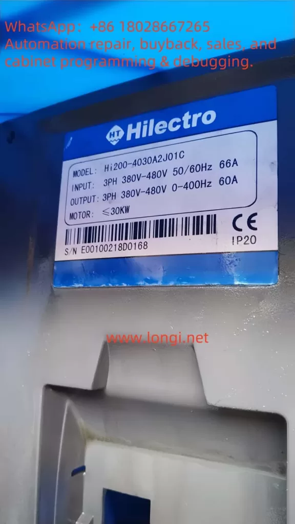
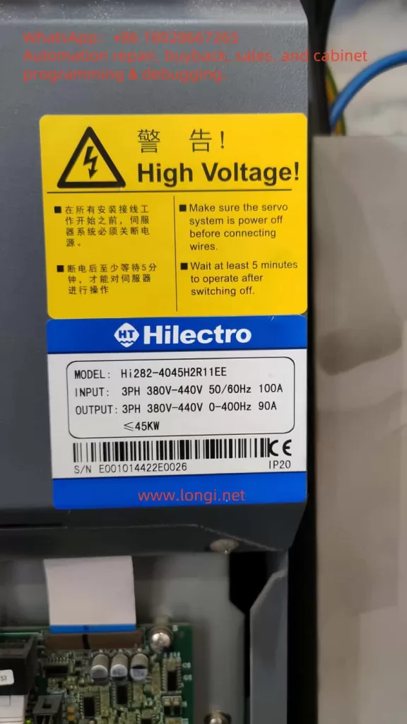
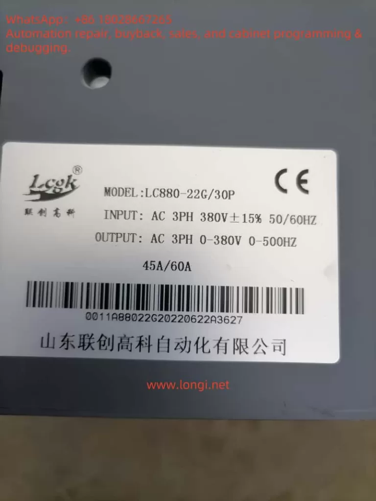
In the LC880 series inverter, the power module supports a three-phase 380V input, with an output range of 0-380V and a frequency range of 0-500Hz. The rated current is 45A/60A (depending on the specific model). Thus, the health status of the power module directly relates to the inverter’s performance and reliability.
Meaning of the E-11 Error Code
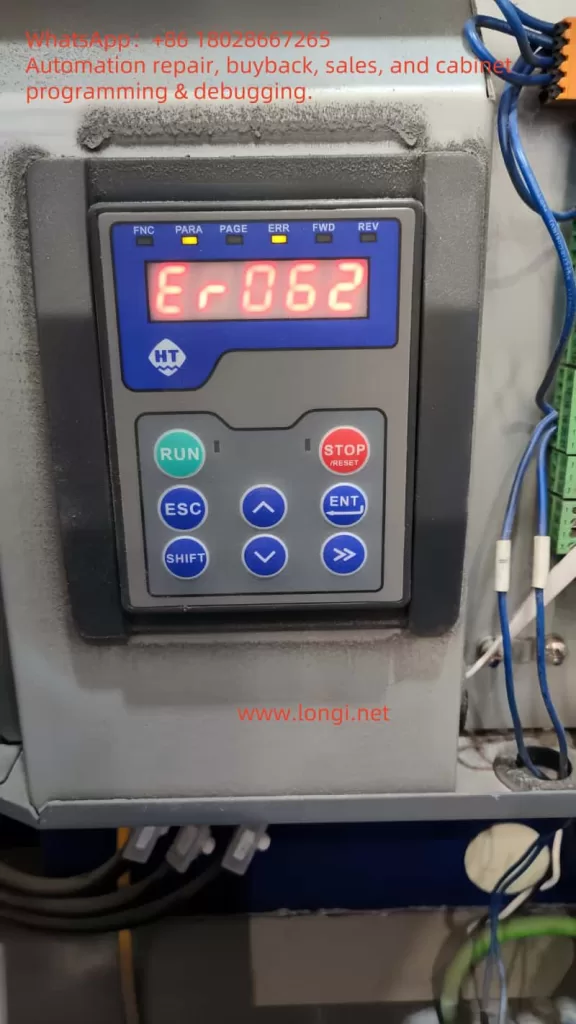
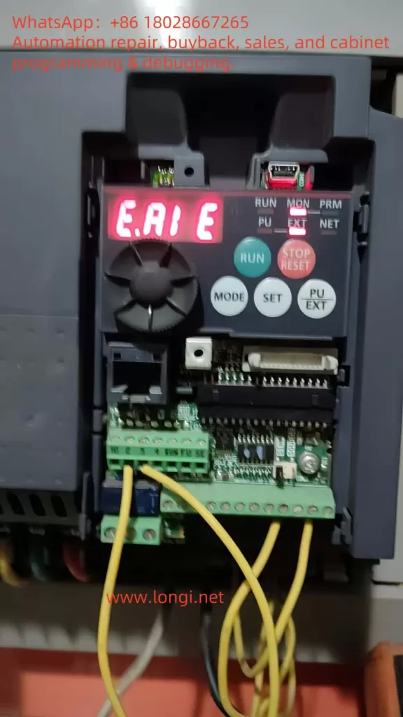
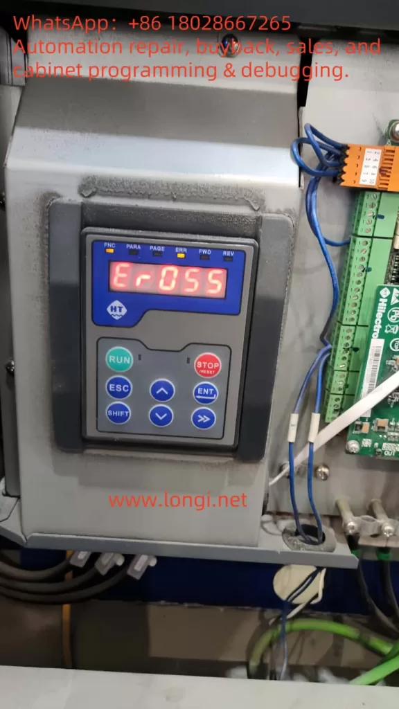
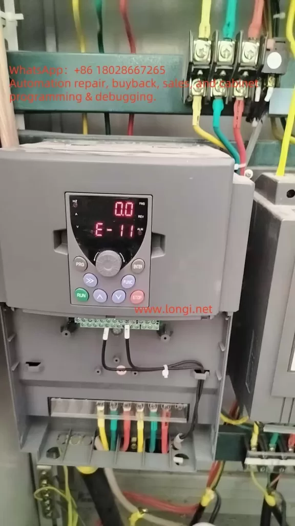
In the LC880 series inverter, the E-11 error code explicitly indicates a “power module fault.” When this error occurs, the inverter’s display will show “E-11”, often accompanied by an “ALM” (alarm) indicator, signifying that the inverter has entered a protective state and stopped running to prevent further damage. This error can be triggered by various factors, including internal short circuits, overvoltage, overcurrent, or damage to the module itself.
Common Causes of Power Module Faults
Power module faults may arise from the following reasons:
Overvoltage or Overcurrent
If the input voltage or current exceeds the inverter’s rated range (e.g., the LC880’s input voltage is 380V ±15%), it can damage the power module. This may result from grid fluctuations, sudden power changes, or improper parameter settings.
Short Circuit
A short circuit at the output or within the inverter can cause excessive current to flow through the power module, damaging its internal components. Short circuits may stem from wiring errors, load faults, or cable insulation damage.
Overheating
Inverters generate significant heat during operation. If the cooling system (e.g., fans) fails or the environment lacks proper ventilation, the power module may overheat and suffer damage. Prolonged high-temperature operation can also accelerate module aging.
Module Aging
As electronic components, power modules have a finite lifespan. Prolonged operation may lead to degraded insulation performance or semiconductor contact failures, triggering faults.
Manufacturing Defects
Although rare, defects during the manufacturing process can cause power modules to fail early in use.
Steps to Troubleshoot the E-11 Error
When the LC880 inverter displays the E-11 error, it is recommended to follow these systematic troubleshooting steps:
Check Power Input
Use a multimeter to measure the input voltage, ensuring it falls within the 380V ±15% range (approximately 323V to 437V). If the voltage is abnormal, check grid stability or use voltage stabilization equipment.
Inspect Wiring
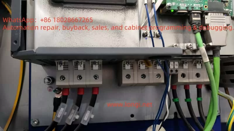
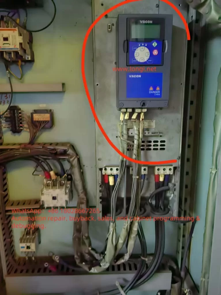
Carefully examine all connections between the inverter, power supply, and motor to ensure they are secure, free from corrosion, looseness, or damage. Pay special attention to the input and output terminals of the power module.
Check Cooling System
Confirm that the inverter’s fans are operating correctly and check for dust or debris blocking the heat sink. Ensure the inverter is installed in a well-ventilated environment, away from high temperatures or humidity.
Verify Load Conditions
Ensure the connected load is within the inverter’s rated capacity (e.g., the LC880-22G/30P has a rated current of 45A/60A). Overloading or sudden load changes may trigger protective mechanisms.
Reset the Inverter
Disconnect the inverter from the power supply, wait at least 5 minutes, and then reconnect it to observe whether the E-11 error disappears. This can rule out faults caused by transient issues.
Use Diagnostic Tools
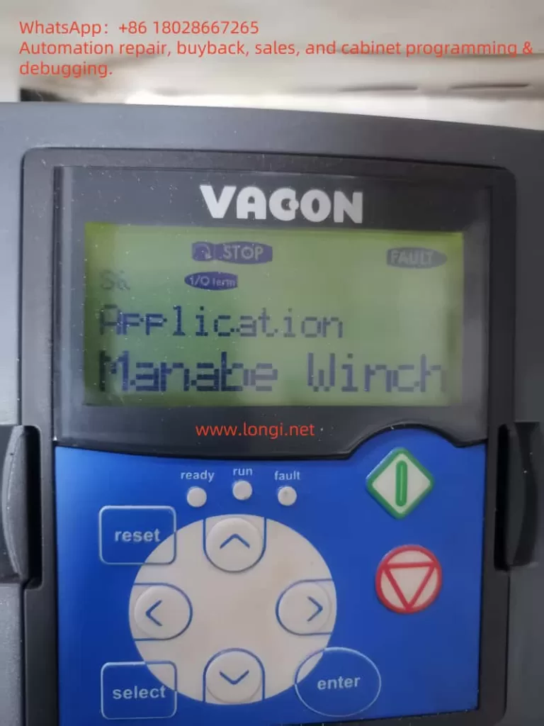
The LC880 series inverter may feature built-in diagnostic functions. Use the “PRG,” “ENTER,” and “FUNC” buttons on the control panel to view error logs or detailed status information for further insight into the fault cause.
Contact Professional Technical Support
If the above steps fail to resolve the issue, the power module itself may be damaged. Contact LCGK technical support or a professional technician, as replacing the power module requires specialized equipment and skills. Do not attempt this operation yourself.
Preventive Measures
To reduce the occurrence of E-11 errors and other faults, the following preventive measures can be taken:
Regular Maintenance
Develop a regular maintenance schedule, including cleaning the heat sink, inspecting wiring, and monitoring the inverter’s operating status. A comprehensive inspection every 6 months is recommended.
Proper Installation
Ensure the inverter is installed in a well-ventilated area, away from dust and humidity. Follow the LC880 series installation guidelines to avoid stacking devices or obstructing ventilation openings.
Real-Time Monitoring
Use the inverter’s monitoring system or external monitoring devices to track parameters such as voltage, current, and temperature. Early detection of anomalies can prevent severe faults.
Personnel Training
Train operators and maintenance personnel to ensure they are familiar with the correct usage and maintenance methods of the LC880 inverter, avoiding faults caused by misoperation.
Case Studies
Case 1: Loose Wiring
Suppose an LC880 inverter in a manufacturing plant displays the E-11 error. The operator first checks the input voltage, confirming it is stable at 380V. Subsequently, an inspection reveals a loose cable at the power module’s output terminal. After re-securing the cable and restarting the inverter, the error disappears, and the system resumes normal operation. This case illustrates that loose wiring is a common cause of faults that can often be resolved through simple checks.
Case 2: Power Module Damage
In another scenario, the operator completes all preliminary checks but still cannot resolve the issue. By consulting the manual, they confirm that the E-11 error may indicate power module damage. After contacting LCGK technical support, a technician arrives and replaces the faulty module, restoring the inverter to normal operation. This case emphasizes the importance of seeking professional help for complex faults.
Conclusion
The E-11 power module fault in the LC880 series inverter is a problem that requires prompt attention to avoid production interruptions or equipment damage. By understanding the fault causes and following systematic troubleshooting steps, users can resolve many common issues. For complex faults, it is advisable to refer to the LC880 user manual or contact us for professional support. Through regular maintenance, proper installation, and real-time monitoring, users can significantly reduce fault occurrences and ensure the long-term stable operation of the inverter.