Posted on Leave a comment

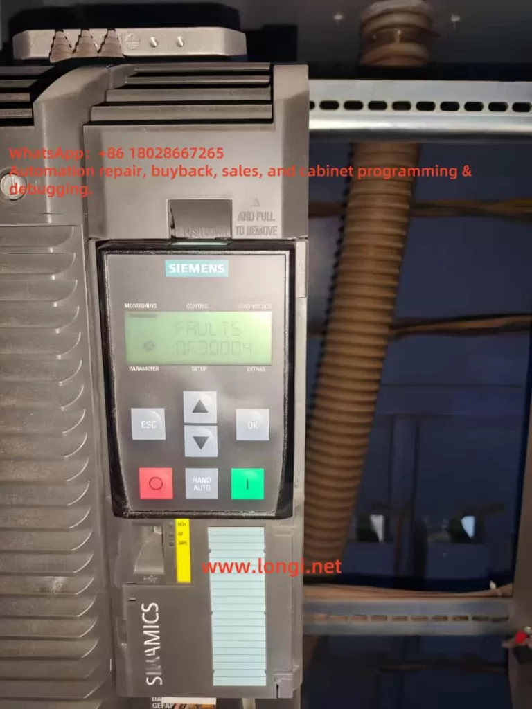
Simplified Debugging Guide for Siemens 400 Series (420/430/440) VFD Drives

Simplified Debugging Guide for Siemens 400 Series (420/430/440) VFD Drives

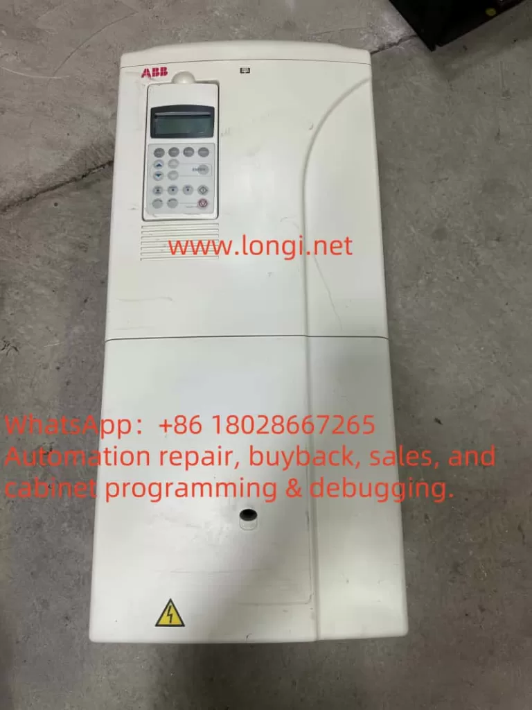
Debugging a Siemens 400 series Variable Frequency Drive (VFD), specifically models 420, 430, and 440, can initially seem daunting due to the multitude of parameters and unfamiliar symbols on the operation panel. However, with a structured approach, even newcomers can quickly master the basics and get these drives running efficiently. This guide will outline a straightforward method for debugging, focusing on essential functions like start/stop control and frequency adjustment, along with some tips for PID operation and parameter adjustment.

Terminal connections of the Siemens 400 Series (420/430/440) VFD Drives

Initial Setup and Terminal Connections

Before diving into the parameter settings, ensure that the terminal wires are properly connected. For basic operation, you’ll need to connect five wires:

  1. Start/Stop Switch: Connect between terminals 5 and 9.
  2. Potentiometer for Frequency Adjustment: Short-circuit terminals 2 and 4, then connect wires from terminals 1, 3, and 4 to the potentiometer, with terminal 3 connected to the center head.
Operation Panel

Understanding Operation Panel Keys

The operation panel of the Siemens VFD is equipped with several keys that serve different functions:

  • Start/Stop Keys: Marked as 1 and 0, these control the run and stop operations.
  • Parameter Adjustment Keys: The P key enters parameter adjustment mode, while the up and down arrows navigate through the parameters. The P key also confirms selections and writes values.
  • Data Display/Reset Key: Press for 2 seconds to view operating data. It also serves as a return key after parameter adjustment and a reset button for fault shutdown.
  • Control Mode Switch Keys: The “Hand” key enables operation via the panel, while the “Auto” key switches to terminal control.
Operation Panel Keys

Quick Start Guide for New Machines

For newly manufactured machines, you can bypass extensive parameter adjustments by understanding the basic button functions and ensuring correct terminal connections. However, for used machines, it’s often simplest to initialize all parameters to their factory settings:

  • Set P0010=30
  • Set P0970=1

After entering these values, the drive will reset, which may take about three minutes.

Parameter access level

PID Operation Adjustment (440 Model)

For PID control, you’ll need to configure specific parameters:

  • P2200=1: Enables PID function, disables conventional frequency settings.
  • P2253: Selects the PID setting signal source (e.g., P2253=755 for analog input 1).
  • P2264: Selects the PID feedback signal source.

Multi-machine operations, such as PID one variable frequency with three power frequencies, require detailed adjustments according to the manual.

Tips for Parameter Adjustment

  • To access PID parameters, set P003=3 for expert-level parameters.
  • Adjust P004 to change specific parameter settings, such as P004=10 for frequency setting values.
  • Define digital terminal functions with P700=2 for digital input control.

Shortcuts and Precautions

  • Fault Reset: Set a terminal to 12 for reverse operation and fault reset.
  • Fixed Frequency Operation: Set a terminal to 15 for multi-stage speed control. Adjust P1000=33 for analog signal plus fixed frequency.
  • V/F Curve Adjustment: Customize the V/F curve with P1300 based on the load type (e.g., constant torque, variable torque).
parameter level

Inertial (Free) Parking Control

For applications requiring inertial parking, set P701=1 for forward start/stop and P702=3 for inertial parking. Connect terminals 5 and 6 in parallel and control via terminal 9.

Special Considerations for High-Power Motors

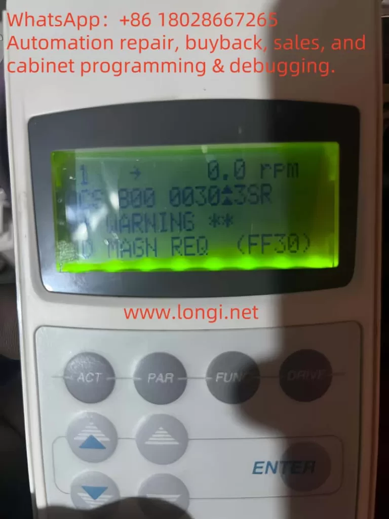
When starting high-power motors, Siemens VFDs may output a certain excitation current to magnetize the stator winding before the motor starts. This is not a malfunction but a feature to reduce starting current.

Conclusion

By following this structured approach, even those new to Siemens 400 series VFDs can quickly become proficient in their operation and debugging. Remember to consult the manual for detailed parameter descriptions and always initialize parameters for used machines to ensure a smooth start. With a basic understanding of the operation panel, terminal connections, and key parameters, you’ll be well-equipped to handle a variety of applications and control requirements.

Posted on Leave a comment

Different scenarios of “GF” ground fault are reflected in the maintenance of Yaskawa 616G3 VSD drive

The power on display is normal. Start the operation, that is, jump “GF” fault, but it does not run or shows no signs of running. I quickly jumped over the ground fault. The “GF” fault at this time is equivalent to the “OC” fault of other frequency converters, and the fault is located in the inverter module or driving circuit. At the moment when the CPU sends the trigger pulse, it detects an abnormally large pressure drop in a certain IGBT tube and fails to open it normally during the arrival of the trigger pulse. In fact, during this time, the current transformer of the frequency converter did not detect the output current signal at all. At this point, the “GF” fault signal is fed back to the CPU by the module fault detection circuit of the driving circuit. (This fault action was determined by testing.)

Repair and inspection: Check the quality of the inverter block, especially the inspection of the trigger terminal cannot be ignored; Check the driving circuit, especially the filter capacitor of the driving power supply, and measure whether the driving voltage is normal, but whether there is a certain current driving ability.

  1. Jumping “GF” fault during operation is a fault reported by the current detection circuit. There are two aspects that need to be distinguished. On the one hand, it is a normal fault shutdown action, where the current transformer detects abnormal overcurrent and reports to the CPU to implement fault shutdown protection; On the one hand, the subsequent current signal processing circuit of the current transformer is faulty, such as the variable value of the resistor element, which causes the “GF” fault voltage setting point to drift, resulting in false alarm faults. The signal from the current transformer is processed through an operational amplifier, sent to the CPU for current display and fault alarm processing, and sent to a voltage comparator, reporting a “GF” fault. (Note: The subsequent circuit of this current transformer was not thoroughly investigated, but it was inferred from numerous fault phenomena and is for reference only.)
    Repair and inspection: When it is confirmed to be a false alarm fault, it is not necessarily necessary to replace the motherboard for repair. Detailed inspection of the current transformer and its subsequent circuits should be able to repair it.
  2. By the way, when an overcurrent fault is reported during operation for OL1, OL2, and OL3, it is detected by the current transformer and subsequent current signal processing circuit during operation. After sending the current signal to the CPU, it is judged, frequency reduced, and processed to report the overcurrent fault signal. For sudden abnormal overcurrent faults, module damage, or abnormal driving circuit faults, the driving circuit will directly feedback to the CPU, and the CPU will report an OC fault.

This suggests different treatments for undervoltage and overvoltage faults in other frequency converters. For undervoltage, after power on, it is detected and delayed for at least 5 seconds before reporting. Started 5 seconds ago and was able to run, but then experienced an undervoltage fault; For overvoltage faults, the fault will trip immediately after power on and operation is prohibited. It can be seen that designers attach greater importance to overvoltage faults than undervoltage faults. It can also be known that overvoltage faults pose greater harm to frequency converters than undervoltage faults do to frequency converters. And the handling of different fault alarms by designers can also be understood.

Posted on Leave a comment

Key Considerations for Selecting and Using Variable Frequency Drives (VFDs)

Variable Frequency Drives (VFDs), also known as frequency converters, are essential devices in modern industrial and commercial applications, providing precise control over motor speed and torque. However, their effective utilization requires a thorough understanding of their operational nuances and precautions. This article delves into the critical aspects of selecting and using VFDs to ensure optimal performance and longevity.

Operational Modes and Control Mechanisms

When integrating a VFD into your system, it’s crucial to understand its operational mode. Some VFDs cannot be directly controlled via the panel for start/stop operations. Instead, they require control terminals to be connected in either the forward or reverse direction. Essentially, the motor’s direction must be predetermined through these terminals before the panel can control the start/stop functions. This setup ensures seamless operational control and prevents any potential misdirections or malfunctions.

For applications involving pole-changing motors, it’s advisable to connect the VFD according to the high-speed connection method initially and then adjust the speed as required. If the motor needs to operate at lower speeds, a medium-speed connection can also be utilized. This flexibility allows for optimized performance across various speed ranges.

Voltage and Connection Considerations

Low-power motors with three-phase angle connections of 220V can be connected in a star configuration when using a VFD. This setup enables direct driving by a 380V VFD, maintaining the motor’s output power without the need to reduce the VFD’s output voltage. This approach is superior in terms of efficiency and performance.

In scenarios where the power supply capacity significantly exceeds the VFD’s capacity, harmonic components in the input current may increase. This can lead to increased losses and potential damage to rectifier diodes and capacitors. To mitigate these effects, installing input reactors is recommended. These devices improve the power factor, reduce the impact of three-phase current imbalance, and provide a degree of lightning protection.

Enhancing Performance and Reducing Interference

Installing an output reactor can further enhance the system’s performance by improving the current waveform, reducing motor operating noise, and boosting energy-saving effects. In cases where VFD-generated interference affects on-site instruments, lowering the carrier frequency can often resolve or mitigate the issue. For high-power motors, a moderate reduction in carrier frequency is advisable, particularly when starting difficulties arise. Adjusting the starting curve by shortening it and reducing the carrier frequency can facilitate smoother starts.

Motors with high operating inertia and specific stopping time requirements may need the addition of braking units and braking resistors. Proper adjustment of these parameters ensures smooth deceleration and stopping. When driving submersible pump motors, selecting a VFD with a higher power rating is recommended due to their larger rated current compared to ordinary motors.

Shutdown Methods and Torque Boosting

In constant pressure water supply systems using a single VFD, a deceleration shutdown method, akin to soft shutdown, can prevent the water hammer effect. However, in systems with one-to-several configurations or power frequency bypasses, a free shutdown method is preferable to avoid contactor tripping and potential damage to the VFD module from the motor’s back electromotive force.

Torque boosting parameters must be carefully set and tested. Excessive torque boosting at low frequencies can cause motor windings to become overexcited, leading to magnetic saturation and a significant torque reduction. This can result in the motor emitting a buzzing sound without rotating, accompanied by a substantial increase in output current, potentially triggering OC faults. Reducing the torque boosting parameter often resolves this issue.

Parameter Protection and Maintenance

If parameters cannot be modified, it may indicate that they are protected or restricted. In such cases, adjusting relevant parameters to disable protection or performing parameter initialization can be necessary. In dusty environments, regular cleaning and dust prevention measures are crucial to maintain VFD performance.

When wiring low-power VFDs (below 1kW), it’s vital to check the voltage level label on the nameplate to ensure correct connection. Misconnecting a 220V VFD to a three-phase 380V supply can cause immediate damage. Manufacturers should clearly mark terminal connections to prevent such mistakes.

The VFD’s power supply should be introduced using an air circuit breaker, with contactors used solely for protection, not for start/stop control. Using contactors for this purpose can shorten the lifespan of the VFD’s energy storage capacitor and impact the rectifier module.

Grounding, Lightning Protection, and Motor Compatibility

Signal shielding wires should be grounded at one end only to avoid circulating currents and interference. In lightning-prone areas, installing lightning arresters near the VFD’s incoming line and ensuring proper grounding is essential.

VFDs are designed based on the rated current of a four-pole motor. When used with motors with more poles, the VFD’s power capacity must be increased to accommodate the higher rated current.

Due to high-frequency leakage current in the VFD’s output circuit, both the motor and control cabinet casings must be reliably grounded. Standard circuit breakers with leakage protection should not be used as power switches for VFDs. If leakage protection is necessary, specialized switches for VFDs or isolation transformers should be used to prevent tripping.

Conclusion

In conclusion, selecting and using VFDs requires a comprehensive understanding of their operational characteristics and precautions. Proper connection, voltage management, interference reduction, parameter setting, and maintenance are critical for ensuring optimal performance, longevity, and safety. By adhering to these guidelines, industries can harness the full potential of VFDs, enhancing motor control, efficiency, and reliability in diverse applications.

Posted on Leave a comment

Exploring the Circuit Diagram and Maintenance Insights of the CONVO VSD Switch Power Supply

Exploring the Circuit Diagram and Maintenance Insights of the CONVO VSD Switch Power Supply

The CONVO VSD switch power supply, specifically designed for the GVF-G type drivers with a power rating of 5.5KW and version number 002-E-P00-01 8.6kVA 13A, presents an intriguing yet robust design in the realm of switch power supplies. Though it may not adhere to the most conventional designs, its performance in practical applications has proven to be reliable, with a notably low failure rate.

Schematic diagram of CONVO inverter switch power supply

Circuit Overview

At the heart of this power supply lies an input stage that receives approximately 550V DC voltage from the autonomous DC home energy storage capacitor. This voltage serves as the foundation for the entire circuit’s operation. The oscillation and driving mechanisms are managed by the widely-used 38440 power chip, which initiates its operation through the voltage and current supplied by components R40, R41, and Z8. While the exact stabilization value of Z8 has not been precisely measured, it is estimated to be around 13V. An LED indicator is conveniently integrated to signal the presence of power.

Once the 3844 chip initiates oscillation, it establishes a power supply voltage for its 7-pin through rectification and filtering circuits comprising D13, Dl4, C30, and C31, facilitated by the BT winding. This power supply not only fuels the chip but also plays a crucial role in output voltage sampling and feedback. The sampled voltage, after being divided by resistors R1 and R2, is fed back to the 2-pin of the 3844 chip. This feedback method, which indirectly samples the output voltage of each channel rather than directly from the transformer’s secondary power supply branch, offers a unique approach albeit with slightly lower control precision and response speed.

Secondary Power Supply Enhancements

To further enhance the power supply’s performance, the +18V and -18V outputs from the secondary winding are routed to the CPU motherboard. Here, they undergo voltage regulation through 7815 and 7915 stabilizers, respectively. Although this adds a layer of complexity to the circuit, it significantly improves the power supply’s stability and reliability. Additionally, the +8V power supply, once introduced to the motherboard, undergoes 7805 voltage regulation to serve as the CPU’s power source.

Current Sampling and Control

The switching tube’s current sampling is achieved through resistor R37, which is series-connected to the source of the K2225 switching tube. This sampled current is then sent to the 3-pin current detection terminal of the 3844 chip. The internal voltage amplifier’s feedback component, connected between the two pins, dictates the sampling voltage’s amplification rate. The 8-pin of the chip, known as the Vref terminal, outputs a stable 5V reference voltage during normal operation. This voltage provides a current path for the external R and C oscillation timing components connected to the 4-pin, ensuring the oscillation frequency’s stability.

The 6-pin of the 3844 chip serves as the pulse output or drive output terminal, introducing pulses to the gate of the K2225 switch through resistor R36. This meticulous control over the switching process is crucial for maintaining efficient and reliable power conversion.

Internal structure diagram of UC3844

24V Output and Fan Control

The 24V output power supply is versatile, providing both the control voltage for the frequency converter’s control terminal and powering two cooling fans. The fans’ operation modes are intelligently controlled by signals from the CPU motherboard, based on parameter settings. These modes typically include running upon power-on, running during operation, and running when the radiator temperature reaches a predefined threshold.

Maintenance Insights

When it comes to maintaining this power supply, several key points should be kept in mind. In the event of a breakdown-induced damage to the K2225 switch tube, a high voltage impulse can be introduced to the 3-pin of the 3844 chip, often leading to its simultaneous damage. Additionally, the R5 resistor may open or experience an increase in resistance value. Similarly, the current sampling resistor R37, connected to the source, is frequently found to be open. Therefore, a comprehensive inspection of these components is imperative before replacing the switch tube. As a direct replacement for the K2225, the K1317 tube can be used.

In conclusion, the CONVO VSD switch power supply, despite its unconventional design, offers a reliable and efficient solution for GVF-G type drivers. Its robust performance in practical applications, coupled with thoughtful design features and straightforward maintenance protocols, makes it a valuable asset in any frequency converter system. By understanding its circuit diagram and adhering to best maintenance practices, one can ensure the longevity and reliability of this power supply in various industrial and commercial applications.

Posted on Leave a comment

What happens to the VSD drive when the no-load current is greater than the load current?

Cause: A cement plant user sent a 75kW micro energy WIN-G9 frequency converter for repair. The cause of the malfunction was that during operation, the frequency converter suddenly caught fire and emitted smoke, causing it to shut down. Upon inspection, the power input circuit of the machine is a three-phase half controlled bridge. Using its controllable rectification principle, the DC main circuit energy storage capacitor is “soft charged”, eliminating the commonly used charging contactor for low-power frequency converters. In fact, the semi controlled bridge here is equivalent to a contactless soft switch. Upon inspection, it was found that there were obvious signs of arc flashover and burning on the terminals of one of the thyristor modules, but the measurement did not indicate a short circuit. During disassembly, it was found that the fixing nut was easily removed, and the cause of the flashover seems to be due to loose connection screws, causing poor contact. This module is a combination of a diode and a unidirectional thyristor. Further check the control board and inverter main circuit, and there are no abnormalities. After removing the module, the remaining two phase half control bridges were used as power inputs. After being powered on, a 2.2kW low-power three-phase motor was tested and there were no issues. After replacing it with a new module of the same model, it was installed on site.

To be cautious, first adjust the operating frequency to 5Hz, and the frequency converter is loaded with a fan. First, disconnect the motor connector and let the motor run at no load. This trial run was a shock! When the frequency is below 5Hz, the no-load operating current is 45A. Although it feels slightly higher, it may be caused by the repair of the motor winding or the adjustment of the parameters of the frequency converter, such as the starting curve or torque compensation, which was not taken into consideration. When the speed was increased to 10Hz, both the current displayed on the frequency converter panel and the output current measured with a clamp meter reached 100A! And the oscillation amplitude of the output current is very large, but when measuring the three-phase output voltage, it is about 70V, balanced and stable. Disconnect the motor connection wire and power on to measure the output of the frequency converter. The output voltage is 70V at 10Hz, 150V at 20Hz, and 250V at 35Hz. As the operating frequency increases, it reaches 400V at 50Hz. During this process, the balance of measuring the three-phase output voltage is very good. The V/F curve output by the frequency converter conforms to the quadratic load torque characteristics. No problem. The output voltage is balanced and stable, while excessive output current and severe current fluctuations are clearly caused by abnormal loads. This is a conclusion drawn from conventional judgment.
Discuss with the relevant technical personnel of the factory, attempting to identify the reasons for the motor and mechanical aspects. For example, whether the motor is newly repaired or whether the winding is poorly wound; Check for wear and unstable operation of bearings; Is there any looseness or non concentricity in the connecting shaft; The wind blades have deformation, etc. Restore the wiring of the original power frequency starting cabinet, compare the power frequency starting motors, and eliminate the above doubts one by one. According to on-site observations, the motor and connected loads are in good condition, and there is almost no electrical and mechanical noise during operation. The no-load current under full speed operation is only less than 35A, with three-phase balance and no fluctuation! There is no problem with the motor and load, and the problem is still with the frequency converter.
So where is the fault location of the frequency converter? It’s a bit scratching my head. Is the current detection inaccurate, causing erroneous output? The current value displayed on the observation panel is close to the value measured by the clamp ammeter, and there should be no problem. Is there still a problem with the CPU motherboard and the output driver waveform incorrect? It doesn’t make sense. All digital circuits, why is the waveform incorrect?
Fortunately, there is another inverter of the same model and power not far from here on site, carrying the same load. That’s great. This has brought great convenience to comparative experiments. The factory was eager to start the machine and provided active cooperation. Swapping the current transformers of two frequency converters is ineffective; Swapping the CPU motherboards of two machines is invalid. Retrieve the DC voltage display of the main circuit, which is 550V, and there is no problem with the voltage sampling circuit. I can no longer figure out which circuit the problem lies in. When the comparison machine is under load, the operating current is 75A at 10Hz. When it reaches 35Hz or above, the operating current only reaches 100A, which is smaller than the current of this motor with no load. The no-load current is much higher than the load current, so there must be a problem with the frequency converter.

During the trial operation, I occasionally measured the three-phase output current of the inverter using a current clamp meter, and even discovered an incredible phenomenon! The input and output currents of this frequency converter are completely disproportionate, with a difference of more than 10 times!
When outputting a 40A current, the input current is a few amperes, which is almost undetectable; When outputting 100A current, the input current is only below 8A! Strange, it doesn’t comply with the law of conservation of energy. Where did the 100A output current come from?! It’s like an airtight water pipe, where 1 cubic meter of water enters and 10 cubic meters of water flows out. The water inside the pipe cannot come out.
We all know that in general, the input current of the frequency converter is always smaller than the output current. The reason is that the energy storage capacitor in the DC circuit acts as if a reactive power compensation cabinet is installed at the motor end. When the frequency converter is unloaded or lightly loaded, a portion of the current is provided by the energy storage capacitor to the load, reducing the current absorbed by the frequency converter from the grid. As the load increases, the input current of the frequency converter increases proportionally. When the rated load is applied, the input current and output current of the frequency converter should be close to equal. When outputting 40A, the input is only a few amperes; When outputting 100A, the input current has reached 70A; When the output current reaches 140A, the input current has also reached this value. Under normal circumstances, there may be a difference in input and output currents, but there will not be an extremely significant difference as mentioned above. The huge difference made me doubt whether the measuring instrument was broken. After changing the watch and retesting, the same result was still obtained.
There’s no way out. Consult the manufacturer. Due to the urgent need to solve the problem and find the answer, it’s not worth considering whether long-distance phone calls are expensive at this time. The technical personnel from the frequency converter manufacturer replied that this model of frequency converter is the earliest produced frequency converter, and there are problems with slightly higher no-load current and current fluctuations, but it is a normal phenomenon and does not affect its use. After being loaded, the current will stabilize. It is best to connect a motor of the same power for testing to see if there is a problem with the motor or load. Problems with motor bearings. If all motor and load issues are eliminated, as long as the three-phase voltage output of the frequency converter is balanced and the output current does not exceed the rated current of the frequency converter, can the machine be tested under no load or on load. Can’t it break down. As for the proportion of input and output currents, it is difficult to have a fixed proportion due to different load conditions. It’s not proportional. Don’t get entangled with the issue of proportion.
Think about it too. As long as the output three-phase voltage is balanced and does not exceed the rated current, can the load test be conducted. Can’t the frequency converter break down. Perhaps after being loaded, there will be no significant fluctuations in the output current. Maybe it’s normal.
We had to conduct a load test and a miracle occurred (which was surprising): when operating at 10 Hz and outputting a current of 40A, the output current was only 7 out of 8 amperes. When operating at 30 Hz, the output current is 60A and the input current is 25A; When operating at 40 Hz, when outputting a current of 100A, the input current is 70 amperes. The operating current has decreased and the fluctuation has decreased, and it is basically stable. The three-phase voltage and three-phase current are both balanced and relatively stable. The problem was inexplicably solved.
Thank you to the manufacturer’s technical personnel for their guidance: why not try the machine on load. But due to encountering this situation for the first time, abnormal current occurs at no load, and it is not dare to increase to full speed for operation. I’m even more afraid to carry it. I always want to find out the reason before loading. I always thought this was an abnormality with the frequency converter.
After the frequency converter was put into operation and returned from the site, I am still pondering this issue.
Remembering the problem of high zero line current in a power plant during maintenance, caused by harmonic components in the transmission line. It’s harmonic current. Is there also a significant harmonic component in the output circuit of the frequency converter during no-load or light load operation? Where does this harmonic component come from? Is the measured result true?

The analysis shows that there are significant harmonic components in the output current during no-load operation. There may be two reasons for the high harmonic current: 1. The output PWM wave of the inverter is not ideal enough, and the modulation method is not optimal. The software control concept has not been optimized (the new machine must have been improved); 2. When unloaded, it is equivalent to a serious mismatch between the power supply capacity and the load capacity. The power supply capacity is much larger than the frequency converter capacity, which is also a major reason for the generation of harmonic currents. When running on load, the capacity matching situation improves, and the harmonic components are greatly reduced. The combination of these two reasons has stumped me, an old electrician. For me, during the test drive, I made an empirical mistake. I was bound by the ratio of input and output currents and almost surrendered.

Posted on Leave a comment

Analysis of IGBT Module and Driver Faults in Variable Frequency Drive Repairs

Analysis of IGBT Module and Driver Faults in Variable Frequency Drive Repairs

In the field of industrial automation, variable frequency drives (VFDs), as key equipment for motor speed control, are crucial for stable operation. However, due to the complex and varied working environments, faults in the IGBT modules and drive circuits within VFDs occasionally occur, causing significant impacts on production. This article delves into the identification, analysis, and handling processes of IGBT module and driver faults through three practical repair cases, aiming to provide valuable references for relevant technicians.

Case 1: Phase Deviation Fault in Dongyuan 7300PA3.7kW VFD
Fault Phenomenon: After powering on, a Dongyuan 7300PA3.7kW VFD had outputs on all U, V, and W phases, but with severe phase deviation.

Fault Diagnosis: Initially suspected as a drive circuit abnormality or IGBT module damage. Measurements revealed an open circuit in the upper arm diode of the U-phase in the inverter circuit. Typically, the IGBT transistor paralleled with this diode was also burnt due to short-circuit current, and the paralleled diode was damaged by the impact.

Repair Process:

  1. After removing the damaged SPIi12E IGBT module, clear all the module pins and prepare to test the six drive circuits.
  2. Upon powering on, the VFD immediately reported an overheating fault, with the CPU locking the drive pulse output, preventing drive circuit quality detection.
  3. Two terminals labeled T1 and T2 on the circuit board, suspected as internal overheating alarm outputs of the module, were observed. By connecting a 5V power supply through a resistor, the other end grounded. When these terminals were left open, the T1 terminal output a high-level module overheating signal through a pull-up resistor, triggering protective shutdown.
  4. After short-circuiting the T1 and T2 terminals, powering on no longer resulted in protective shutdown. It was found that the U-phase upper arm IGBT drive circuit had no trigger pulse output. After replacing the drive circuit IC/PC923, the six-pulse output returned to normal.
  5. A new IGBT inverter module was installed, the short-circuit wire between T1 and T2 was removed, and the VFD operated normally after powering on.
    Experience Summary: When an IGBT tube is damaged, the corresponding drive IC is often damaged by the impact as well. Before replacing the new module, be sure to check the drive IC in the same branch to avoid damaging the new module again due to drive circuit abnormalities.

Case 2: Repair of Lightning-Damaged Alpha 18.5kW VFD
Fault Phenomenon: An Alpha 18.5kW VFD was damaged by lightning, with the CPU motherboard reporting a 2501 error and panel operations failing.

Fault Diagnosis: Lightning caused damage to the CPU and surrounding communication circuits.

Repair Process:

  1. Temporarily ignoring the CPU motherboard issue, repair the drive board first. It was found that six A316J chips were responsible for six drive pulse outputs, with three upper arm pulse drive circuits damaged.
  2. As an alternative, three A316J chips (for three-phase lower arm drives) were used as three-phase OC signal alarm outputs, and the remaining three were replaced with 3120 (identical to PL250V) to drive the optocoupler ICs.
  3. The new ICs were adapted and soldered, and the input circuit was adjusted to ensure normal operation of the new ICs.
  4. After replacing the new CPU motherboard, the static output voltage and dynamic pulse output of the six drive circuits were tested and found to be normal.
  5. The damaged IGBT module was replaced, and the VFD resumed normal operation.

Case 3: Repair of Phase Deviation in a 7.5kW VFD
Fault Phenomenon: A user reported that a 7.5kW VFD had output but could not operate normally, with phase deviation present.

Fault Diagnosis: It was found that one of the six drive circuits was abnormal, with the drive IC model being PC929 (or A4503?). Measurements showed no pulse output at the input and output terminals of the drive IC.

Repair Process:

  1. Suspecting a fault in the CPU’s internal pin circuit, the input terminal of the PC929 was disconnected, and it was found that the voltage at the CPU’s pulse output terminal increased. However, when the drive IC was connected, the voltage dropped to nearly 0V.
  2. It was analyzed that the CPU directly drove the photoconductive tube, and long-term high-current output led to aging faults in the output stage. It was decided to enhance the signal voltage through an external amplification circuit.
  3. An amplification circuit was constructed using two NPN-type transistors and resistors to amplify the CPU’s pulse signal before inputting it to the drive IC.
  4. After powering on, the six-pulse output was normal, and the inverter module was powered on, with normal three-phase voltage output.
    Experience Summary: For aging faults in the CPU’s output stage, amplifying the signal voltage through an external circuit is an effective repair method, which not only saves repair costs but also shortens repair time.

In summary, IGBT module and driver faults are common challenges in VFD repairs. Through meticulous fault diagnosis, reasonable repair strategies, and innovative repair methods, these issues can be effectively resolved, ensuring the stable operation of VFDs. It is hoped that the sharing in this article can provide valuable references and insights for technicians.

Posted on Leave a comment

Repair Guide for PI-18 Type 11kW POWTRAN VFD Drive OC Alarm

Repairing a PI-18 type 11kW POWTRAN VFD (Variable Frequency Drive) can be a challenging task, especially when dealing with OC (Overcurrent) alarms. This comprehensive guide aims to provide a structured and logical approach to diagnosing and fixing OC alarms in this specific VFD model, integrating both practical experiences and technical insights from various sources.

POWTRAN VFD DRIVE

Understanding the OC Alarm

The OC alarm in a VFD typically indicates an overcurrent condition, which can be caused by various factors, including module damage, faulty driving circuits, or incorrect trigger pulses. In the PI-18 type 11kW POWTRAN VFD, the OC alarm often involves complex diagnostics due to the intricate interplay of its components.

Initial Diagnostics

1. Module Inspection:
The first step in troubleshooting an OC alarm is to inspect the inverter module. Damage to the module isn’t always apparent through simple visual inspection or basic electrical tests. It’s crucial to check for short circuits or open circuits not only in the main current terminals (R, S, T, U, V, W) but also between the triggering terminals and the main terminals, as well as within the triggering terminals themselves.

2. Measuring with a Multimeter:
While measuring the main terminals for short circuits is a good start, it doesn’t guarantee that the module is free from damage. Hidden issues such as leakage currents or degraded performance can still be present. Therefore, a more thorough approach is needed, including verifying the quality of the module under controlled conditions.

Detailed Diagnostics

1. Power-On Testing:
Before connecting the module to the full DC bus voltage, it’s advisable to perform a power-on test using a lower DC voltage. This can be achieved by using a 24V switching power supply. This step helps to identify any potential issues without risking further damage to the module or the drive.

2. Checking the Driving Circuit:
The driving circuit plays a critical role in the operation of the VFD. It’s essential to inspect components such as the A4504 optocoupler, MC33153 driver, and P521 feedback optocoupler. These components are responsible for isolating the CPU input trigger pulse from the main circuit, driving the module, and feeding back any abnormal conditions to the CPU, respectively.

3. Verifying Trigger Pulses:
Using an oscilloscope, check the amplitude and variation of the six trigger pulses. Any deviations from the expected waveform can indicate issues in the driving circuit or the trigger pulse generation.

4. Observing Output Waveforms:
When powering the VFD with a 24V supply, observe the output voltage of U, V, and W. If the voltage is lower than expected or there are periodic contractions in the output amplitude, this could be an indication of a faulty module.

Repair Steps

1. Module Replacement:
If the initial diagnostics indicate a faulty module, replace it with a known good one. Before soldering the new module onto the circuit board, perform the same tests using a 24V supply to ensure its functionality.

2. Connecting the DC Bus:
Once the module has passed the initial tests, you can proceed to connect it to the DC bus. However, it’s recommended to do this in a controlled manner, such as connecting the DC power supply circuit in series with a light bulb. This acts as a current limiter and can help prevent damage in case of any remaining issues.

3. Final Testing:
After connecting the module to the full DC bus, perform a no-load power transmission test. Measure the three-phase balance of the output and ensure there are no abnormalities. If everything functions correctly, you can then connect the original DC power supply and put the VFD through its final tests.

Best Practices

  • Use Caution with Disassembled Modules: Disassembled modules are not inherently unusable, but they should be treated with caution. Always test them thoroughly before installation to avoid potential issues.
  • Thorough Cleaning: If a module is found to be faulty, clean the solder on the pins before returning or replacing it. This ensures a good connection when the new module is soldered into place.
  • Documentation: Keep detailed records of your diagnostics and repair steps. This can help in future repairs and provide valuable information for troubleshooting similar issues.
POWTRAN VFD Internal Diagram

Conclusion

Repairing a PI-18 type 11kW POWTRAN VFD with an OC alarm requires a systematic and methodical approach. By following the steps outlined in this guide, you can effectively diagnose and fix the issue, ensuring the VFD operates reliably and efficiently. Remember, safety is paramount when working with electrical components, so always take the necessary precautions and follow best practices. With the right tools, knowledge, and approach, you can successfully tackle even the most challenging VFD repairs.

Posted on Leave a comment

In-depth Analysis of A316J Optocoupler Drive Characteristics and Its Protection Mechanism for IGBT Modules

In the field of modern power electronics, the inverter module, as the core component of frequency converters, has its stability and reliability directly related to the operational efficiency and safety of the entire system. The A316J, as a widely used drive IC for inverter modules, occupies an important position in numerous frequency converter models due to its excellent performance. This article aims to deeply explore the characteristics of the A316J optocoupler drive, especially its fault detection and protection mechanisms, and analyze how these features affect the health of IGBT modules, thereby providing valuable references for professionals in related fields.

Internal structure diagram of optocoupler A316J

I. Overview of the A316J Optocoupler Drive

The A316J serves as a crucial drive component for inverter modules, primarily functioning to receive drive pulse signals from the CPU and convert them into drive signals suitable for IGBT module operation. This drive IC forms a closed loop with the C (collector) and E (emitter) poles of the driven IGBT tube through its 14th and 16th pins’ peripheral circuits, enabling effective monitoring of the IGBT tube’s operating state. During normal operation, the IGBT tube has a low on-state resistance, with a voltage drop typically below 3V. However, when abnormal overcurrent conditions occur, the voltage drop across the IGBT tube rises sharply, potentially damaging the tube. At this point, the A316J plays a pivotal role by detecting changes in the voltage drop, promptly blocking the output pulse, and sending an OC (overcurrent) alarm signal to the CPU to protect the IGBT module from further damage.

II. Fault Detection and Protection Mechanism of the A316J

The fault detection and protection mechanism of the A316J is one of its core functions. This mechanism continuously monitors the operating state of the IGBT tube and immediately takes protective measures once abnormalities are detected. Specifically, the A316J can detect the following three fault conditions:

  1. Excessive Operating Current Due to Load Abnormalities: When the load abnormalities cause the operating current to exceed the rated current significantly (usually by more than three times), the voltage drop across the IGBT tube rises rapidly, exceeding the 7V threshold. At this point, the A316J immediately blocks the output pulse and sends an OC alarm signal to the CPU.
  2. Open-Circuit Damage to the IGBT Tube: If the IGBT tube experiences open-circuit damage, it will fail to operate normally, resulting in an abnormally high voltage drop. The A316J can also detect this abnormality and take corresponding protective measures.
  3. Poor Drive Circuit: A poor drive circuit may cause the IGBT tube to be under-excited. Even if the output current is relatively small, the tube is in a partially conducting and randomly switching-off state, and the voltage drop may still exceed the action threshold. In this case, the A316J will also send an OC signal for alarm.
INVERTER main circuit structure and IGBT circuit

III. Harm to IGBT Modules Caused by A316J Faults and Case Study

Faults in the A316J not only affect its normal operation but may also cause severe damage to IGBT modules. The following is a typical fault case analysis:

A small-power frequency converter experienced abnormal sounds and vibrations from the motor, accompanied by OC shutdown phenomena, when the frequency rose above 20Hz after replacing a damaged IGBT module. After inspection, the fault was found to be caused by the failure of filtering capacitors in the peripheral circuit of the A316J. The failure of these capacitors reduced the power supply’s load-carrying capacity, making it difficult for the IGBT tube to turn on properly during high-speed or loaded operation, resulting in a large on-state resistance, severe three-phase imbalance, and subsequent motor vibration and OC alarms.

IV. Preventive Measures and Maintenance Suggestions

Given the potential harm caused by A316J faults to IGBT modules, the following are some preventive measures and maintenance suggestions:

  1. Regularly Check Filtering Capacitors in the Drive Power Supply: Ensure that the capacitance meets the specified requirements to avoid reduced power supply load-carrying capacity due to capacitor failure.
  2. Enhance Cooling Measures: For models with longer usage times or limited spaces, special attention should be paid to cooling issues to prevent component damage due to excessive temperatures.
  3. Regular Maintenance and Inspection: Regularly maintain and inspect frequency converters to promptly identify and address potential faults, ensuring the stable operation of the system.

In summary, as a key component of the inverter module, the performance stability and reliability of the A316J optocoupler drive are crucial to the operation of IGBT modules and even the entire frequency converter. By deeply understanding the characteristics and protection mechanisms of the A316J and adopting effective preventive measures and maintenance suggestions, we can effectively reduce the occurrence of faults and improve the stability and safety of the system.

Posted on Leave a comment

Solving Frequency Fluctuations and False Shutdowns in Kemron VFDs: A Comprehensive Guide

In the gypsum board production industry, precision control of cutting, water supply, and belt conveyors is crucial. To achieve this, many facilities install frequency converters (VFDs) like those from the Comron brand. However, issues such as fluctuating frequency values and unexplained shutdowns can disrupt operations and reduce efficiency. This article delves into these problems, their causes, and effective solutions, ensuring your VFDs operate smoothly.

The Challenge: Frequency Fluctuations and False Shutdowns

During the installation of four low-power Comron VFDs in a control cabinet for synchronous speed control, significant fluctuations in displayed speed values were observed. These fluctuations were as high as ±30 revolutions, raising concerns about speed instability. Initially, grounding the main circuit’s G terminal and shielding the speed control signal line improved the situation but did not eliminate the problem entirely.

Further investigation revealed that the issue persisted even when running a single VFD unit, with fluctuations increasing when multiple units were operational. Despite attempts to resolve the issue, including consultations with the manufacturer, a definitive solution was not found. However, the problem was temporarily deemed tolerable and left unresolved.

A Similar Issue: Repeated False Shutdowns

In another gypsum board factory, a 3.7kW water supply VFD experienced repeated shutdowns, sometimes exceeding ten times a day. On-site observations showed erratic speed display values, with all three digits flashing, and the FWD indicator light also flashing intermittently. The VFD would either recover and continue operating or require a restart. Occasionally, it would display F000 and enter the parameter setting state inexplicably, suggesting external interference with the CPU’s operation.

Identifying the Root Cause: Signal Interference

Given the symptoms, it was evident that signal interference was the culprit. The VFD’s carrier wave, generated during operation, was entering the CPU’s I/O port via the operation panel’s connection cable. This interference caused fluctuations in input frequency and display values and, in severe cases, triggered random shutdowns.

Step-by-Step Solution: Combating Interference

  1. Conventional Grounding Treatment:
    • As a first step, ensure proper grounding of the main circuit and shield the speed control signal line. While this may offer some improvement, it often does not completely resolve the issue.
  2. Adjusting Carrier Frequency:
    • Lowering the VFD’s carrier frequency to the minimum setting (e.g., 2kHz) can reduce interference. This step may provide slight improvements but is usually not sufficient on its own.
  3. Shielding the Connection Cable:
    • Wrapping a layer of tin foil around the cable connecting the control panel to the VFD can further reduce interference. This method is effective but may not be the most elegant or long-term solution.
  4. Using Magnetic Rings:
    • The most effective solution involves installing magnetic rings on the signal line. Purchase magnetic rings with a moderate diameter and wind 2-3 turns at each end of the connecting wire. This simple yet powerful method can eliminate speed value fluctuations and stabilize VFD operation.

Results: Stable and Reliable Operation

After implementing the above steps, particularly the use of magnetic rings, the displayed speed value stabilized, and the flashing FWD indicator light ceased. Even the smallest fluctuations disappeared, ensuring consistent and reliable VFD performance.

Conclusion: Ensuring Smooth VFD Operation

Frequency fluctuations and false shutdowns in Kemron VFDs can disrupt production and reduce efficiency. By understanding the root cause—signal interference—and implementing targeted solutions, you can ensure your VFDs operate smoothly and reliably. Grounding treatments, adjusting carrier frequencies, and shielding connection cables are helpful steps, but using magnetic rings is the most effective solution. With these measures in place, you can maintain precise control over your gypsum board production process, enhancing productivity and quality.

By addressing these issues proactively and implementing the recommended solutions, you can avoid costly downtime and ensure your VFDs contribute to the success of your gypsum board production operations.

Posted on Leave a comment

Repair Process and Analysis of a TECO 7200GA-22kW VSD after a Lightning Strike

Repair Process and Analysis of a TECO 7200GA-22kW VSD after a Lightning Strike

In the realm of industrial equipment maintenance, dealing with the aftermath of a lightning strike on sensitive electronic devices such as variable speed drives (VSDs) can be particularly challenging. This case study delves into the repair process of a TECO 7200GA-22kW (41kVA) VSD that suffered damage due to a lightning fault. By dissecting the diagnostic steps, repairs, and underlying issues, we aim to provide insights that can aid technicians in similar situations.

Initial Assessment and Repairs

Upon receiving the damaged VSD for repair, the initial inspection revealed that the input rectifier module, switch tube, and shunt tube of the switching power supply had been compromised by the lightning strike. These components were promptly replaced. Following the replacements, the operation panel screen lit up normally, suggesting that the core functionality of the VSD had not been severely impacted.

Subsequent tests on the negative pressure and optocoupler drive input signals for the six channels returned normal results, further reassuring that the repair was progressing positively. However, during the assembly test of the entire unit, an Over Current (OC) fault was triggered immediately upon power-up. Interestingly, the VSD could be reset and started, with the screen displaying normal frequency output values. But during actual testing, no three-phase voltage output was observed at the U, V, and W terminals.

Investigating the Drive Circuit

The local driving ICs employed in the VSD were optocouplers PC923 and PC929, which worked in conjunction with the SN0357 to relay OC signals. An examination of the power amplifier circuit on the output side of the driving ICs and the IGBT tube’s detection circuit revealed no abnormalities. The focus then shifted to the pulse input pin of the PC923 optocoupler, where an anomaly was detected.

Specifically, the level of pin 3 was unexpectedly high while pin 2 was low. This raised the question of whether the driver power supply had been reversed. Normally, in optocoupler circuits, the two pins (anode of the photodiode) are powered by +5V and regulated to provide an excitation power of around 4V, while the third pin (cathode of the photodiode) connects to the pulse output terminal of the CPU. A low-level output is effective, meaning that when the CPU outputs a signal, current is drawn from pin 3 of the PC923, causing the diode to conduct.

Diagnosing the Power Supply Issue

Further investigation revealed that the power supply to pin 2 of the PC923 was a simple series-connected voltage regulator comprising a transistor and a voltage regulator. A faulty base bias resistance in this circuit was identified as the culprit, resulting in a zero supply voltage to pin 2. Replacing the bias resistor restored the voltage levels on pins 2 and 3 of the PC923 to normal. Consequently, upon receiving an operation command, the VSD began outputting voltage from the U, V, and W terminals.

Addressing the OC Fault

With the output issue resolved, attention turned to the persistent OC fault upon power-up. Measurements of the SN0357 optocoupler, responsible for transmitting the OC signal, showed that the voltage value of the two pins on the input side was zero, indicating no OC signal was being input. However, the voltage on the output side of the three optocouplers was 0.5V, which was abnormal. In the absence of an OC signal, the voltage between the two pins should have been 5V (one pin connected to a 5V ground level).

This anomaly pointed to a problem with the 5V pull-up resistance on the signal output pin, which had either changed or become open-circuit. As a result, the CPU erroneously interpreted the situation as receiving an OC signal from the drive circuit, triggering the alarm. Connecting a 10k resistor between the signal output pin and the 5V power supply resolved the issue. Subsequent power-ups showed the signal output pin at 5V, and the OC fault no longer occurred.

Root Cause Analysis

Both faults—the lack of output voltage and the OC fault upon power-up—stemmed from a common issue: power loss. The input pin of the pulse signal and the output pin of the OC signal were directly connected to the CPU pin. When the pull-up high level disappeared, the CPU pin was left with only a low level of 0.5V, insufficient to drive the optocoupler or trigger the inverter module. This low level also led to the detection of OC signals and the jumping of the OC fault code during power-up.

Additional Insights

The motherboards of various Dongyuan VSD series exhibit good replacement characteristics, requiring only the adjustment of the VSD’s capacity value after replacement. This adjustment automatically modifies the relevant parameters for checking the motor’s rated current value. It is worth noting that Dongyuan VSDs’ capacity labeling is often based on kVA rather than kW. For instance, a 22kW capacity is labeled as 41kVA with a rated current of approximately 48A.

The relationship between kW, kVA, and HP values can be confusing for users. In simple terms, 1HP equals 0.75kW, indicating that HP is less than the kW value. kW represents active power, closely approximating the actual power value, while kVA is the apparent power, which includes both active and reactive power components. When selecting a VSD, the kVA value should be chosen based on the rated current value, as it accounts for the reactive power consumption of inductive loads like motors.

Conclusion

This case study underscores the importance of thorough diagnostics and a methodical approach in repairing VSDs damaged by lightning strikes. By understanding the intricacies of the drive circuit, power supply, and signaling mechanisms, technicians can effectively pinpoint and resolve issues, ensuring the reliable operation of industrial equipment. The repair process not only restored the VSD to working condition but also provided valuable insights into the underlying causes of the faults, contributing to a deeper understanding of VSD technology.