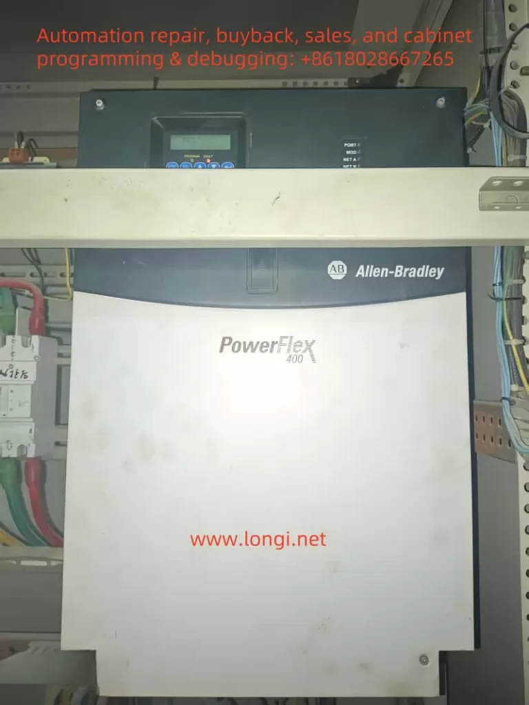
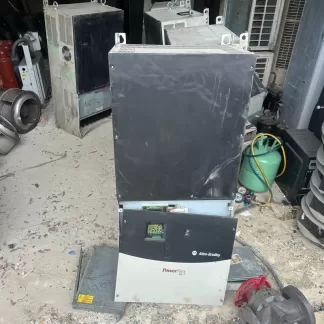
The Rockwell (Allen-Bradley) PowerFlex 400 series inverter is a powerful industrial control device designed for applications such as fans and pumps, offering flexibility, ease of configuration, and high reliability. This article, based on the PowerFlex 400 series manual, provides a detailed guide on its operation panel functions, external terminal control methods, and fault code troubleshooting. It aims to help users fully grasp the skills needed for operating and maintaining the equipment. This guide is clear, logical, and comprehensive, suitable for engineers, technicians, and field operators.
I. Introduction to the Operation Panel Functions
The PowerFlex 400 series inverter is equipped with a user-friendly Human Interface Module (HIM), which allows parameter configuration, status monitoring, and fault diagnosis via buttons and a display screen. Below is a detailed explanation of its main functions and operation steps.
1. Panel Layout and Button Functions
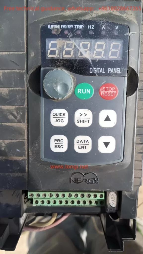
The operation panel is the core interface for user interaction with the inverter. Its layout includes:
- LCD Display: Shows running frequency, parameter numbers, fault codes, etc.
- Arrow Keys (Up, Down, Left, Right): For menu navigation and parameter adjustment.
- Enter Key: Confirms selections or saves settings.
- Esc Key: Returns to the previous menu or cancels operations.
- Start/Stop Keys: Starts or stops the inverter in manual mode (must be enabled via parameters).
Familiarity with these buttons allows users to easily navigate menus and complete configurations.
2. Copying Parameters to Another Inverter
The PowerFlex 400 supports parameter copying, making it easy to replicate settings across multiple devices. Follow these steps:
- Step 1: On the source inverter’s HIM panel, enter the “Parameter” menu.
- Step 2: Select “Copy to HIM” to save parameters to the panel’s memory.
- Step 3: Remove the HIM panel from the source inverter and insert it into the target inverter.
- Step 4: On the target inverter, enter the “Parameter” menu and select “Copy from HIM.”
- Step 5: Confirm to load the parameters onto the target inverter.
- Note: Both inverters must be of the same model and firmware version to avoid compatibility issues.
3. Initializing Parameter Settings
To reset the inverter to factory settings, follow these steps:
- Step 1: Enter the “Parameter” menu and locate parameter P041 (Reset to Defaults).
- Step 2: Set P041 to “1” (Reset) and press Enter to confirm.
- Step 3: Wait for the inverter to complete the reset; the display will indicate success.
- Note: Initialization erases all user settings; it is recommended to back up parameters first.
4. Setting Password and Parameter Access Restrictions
To protect parameters from unauthorized changes, the PowerFlex 400 offers a password feature:
- Step 1: Enter the “Parameter” menu and find parameter P042 (Password).
- Step 2: Enter a four-digit password (e.g., “1234”) and press Enter to save.
- Step 3: Set parameter P043 (Password Enable) to “1” to activate password protection.
- Step 4: In parameter P044 (Access Level), select the access level:
- “0”: Basic (limited to common parameters).
- “1”: Advanced (access to all parameters).
- Note: If the password is forgotten, contact technical support or use specialized tools to unlock it.
II. External Terminal Control and Speed Regulation
The PowerFlex 400 supports forward/reverse control and frequency adjustment via external terminals, ideal for scenarios requiring manual switches or potentiometer control. Below are the wiring and parameter configuration methods.
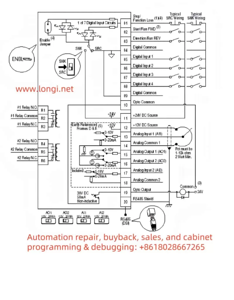
1. External Terminal Forward/Reverse Control
To control start, stop, and direction via external switches, follow this wiring and setup:
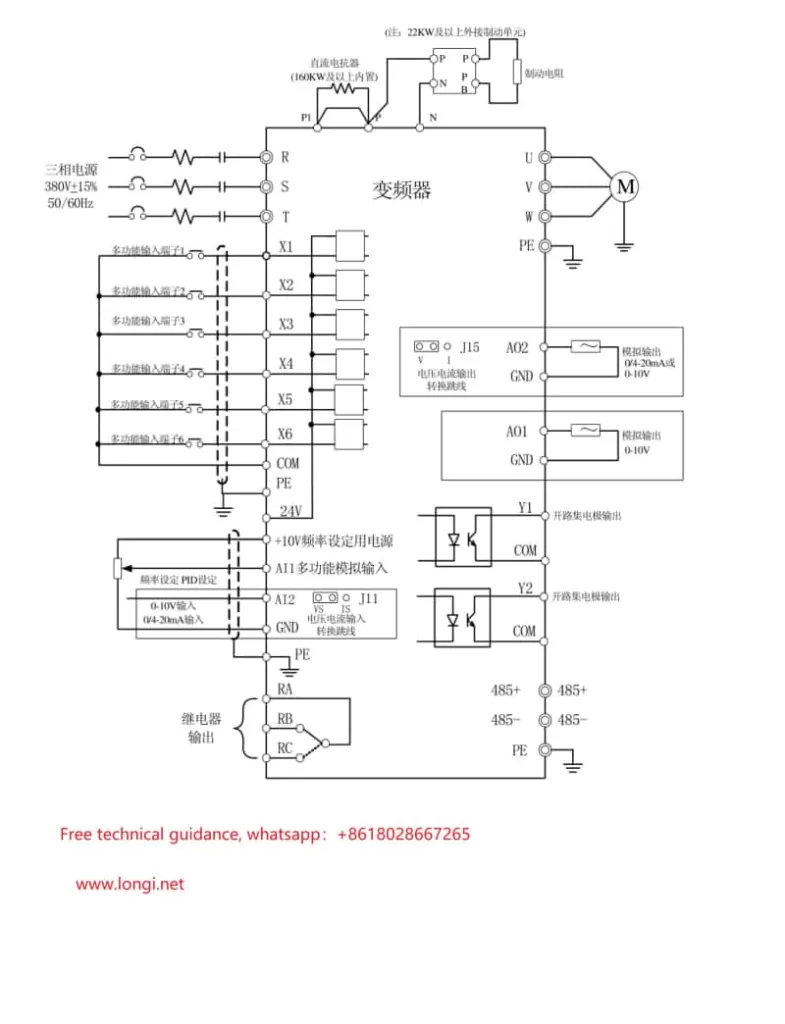
- Wiring Instructions:
- Terminal 11 (Digital In 1): Connect to one end of the start/stop switch.
- Terminal 12 (Digital In 2): Connect to the direction selection switch (forward/reverse).
- Terminal 01 (Common): Common terminal, connect to the other end of the switches.
- Parameter Settings:
- P036 (Start Source): Set to “2” (2-Wire Control) to enable two-wire control mode.
- P037 (Stop Mode): Set to “1” (Ramp) for smooth stopping.
- A051 (Digital In1 Sel): Set to “4” (Run) to define terminal 11 as run control.
- A052 (Digital In2 Sel): Set to “6” (Direction) to define terminal 12 as direction control.
- Operation Verification: Close terminal 11 to start the inverter; switch terminal 12 to control direction.
2. External Potentiometer for Frequency Control
To adjust the operating frequency with an external potentiometer, follow this wiring and configuration:
- Wiring Instructions:
- Terminal 15 (Analog In 1+): Connect to the potentiometer’s wiper (signal output).
- Terminal 16 (Analog In 1-): Connect to the potentiometer’s low potential end.
- Terminal 17 (Analog In Common): Connect to the potentiometer’s high potential end (usually 10V supply).
- Parameter Settings:
- P038 (Speed Reference): Set to “2” (Analog In 1) to select analog input 1 as the frequency reference.
- A065 (Analog In 1 Hi): Set to the maximum frequency (e.g., 60 Hz), corresponding to the potentiometer’s maximum.
- A066 (Analog In 1 Lo): Set to the minimum frequency (e.g., 0 Hz), corresponding to the potentiometer’s minimum.
- Operation Verification: Rotate the potentiometer to observe smooth frequency changes from minimum to maximum.
With these configurations, users can achieve external switch control for start/stop and direction, while precisely adjusting speed with a potentiometer.
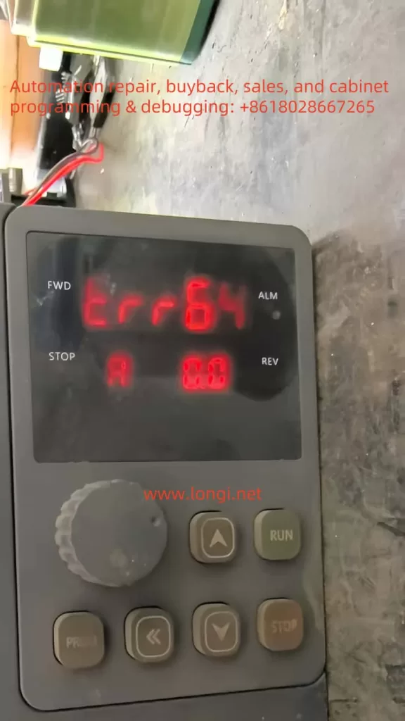
III. Fault Codes and Their Handling
The PowerFlex 400 may trigger faults due to power, load, or environmental issues. Understanding fault codes and their solutions is crucial. Below are common fault codes, their meanings, and troubleshooting steps.
1. Common Fault Codes and Meanings
- F005 (OverVoltage)
- Meaning: DC bus voltage exceeds the allowable range, often due to rapid deceleration or power fluctuations.
- Solution:
- Check if the input power voltage is too high.
- Extend the deceleration time in parameter P039 (Decel Time).
- If frequent, consider installing a braking resistor.
- F012 (UnderVoltage)
- Meaning: DC bus voltage is below normal, possibly due to power interruption or poor wiring.
- Solution:
- Ensure the input power is stable and within the rated range.
- Check for loose power connections.
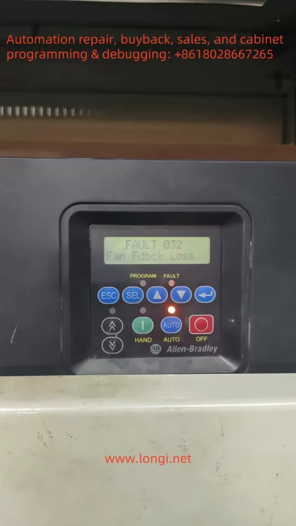
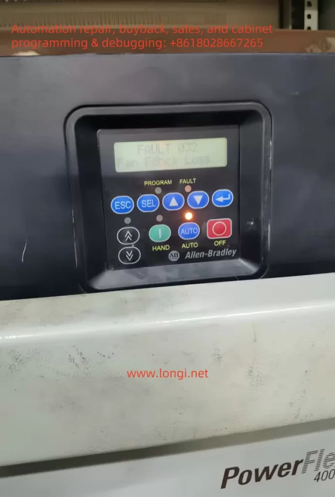
- F032 (Fan Feedback Loss)
- Meaning: Cooling fan is not working or feedback signal is abnormal.
- Solution:
- Check for foreign objects blocking the fan.
- Ensure the fan power cable is properly connected.
- Replace the fan if damaged.
- F048 (Params Defaulted)
- Meaning: Parameters have been reset to factory defaults.
- Solution: Reconfigure necessary parameters; consider backing up settings.
- F081 (Comm Loss)
- Meaning: Communication with the host or network is lost.
- Solution:
- Check communication cables and connectors.
- Verify parameter A103 (Comm Format) is set correctly.
2. General Fault Handling Steps
- Step 1: Record the fault code and operating conditions at the time.
- Step 2: Refer to the manual’s fault code table to analyze possible causes.
- Step 3: Check power, wiring, and load conditions to rule out external factors.
- Step 4: Press the “Fault Reset” button to attempt a reset; resume operation if successful.
- Step 5: If the fault recurs, contact Rockwell technical support for further assistance.
Conclusion
The Rockwell PowerFlex 400 series inverter, with its outstanding performance and flexible operation, is a preferred choice in industrial settings. This article covers the operation panel functions, external terminal control, and fault code handling, providing a comprehensive user guide. By mastering panel operations, users can efficiently configure parameters; through external terminal setups, they can achieve flexible control schemes; and with fault code analysis, they can quickly resolve issues to ensure stable operation. This guide aims to offer practical support, enhancing users’ efficiency and maintenance capabilities with the equipment.