Posted on Leave a comment

In-depth Analysis of ABB VFD ACS355 Series Inverter: Features, Faults, and Alarm Codes

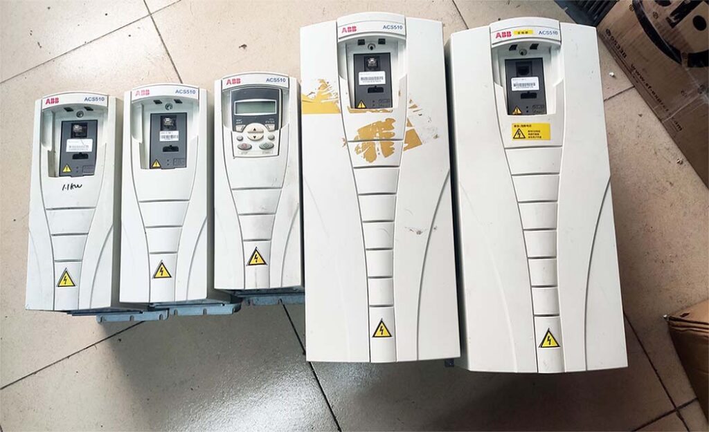
ABB VFD ACS355 Series Inverter: Technological Innovation and Feature Overview

ABB’s VFD ACS355 series of inverters, as a leading player in variable frequency drive technology, stands out for its superior performance, user-friendly interface, and high reliability, occupying a prominent position in numerous industrial applications. Below is an in-depth exploration of the core features of this series of inverters:

  1. Compact and Efficient Design Philosophy
    • Space Optimization: The compact design of the ACS355 series inverters significantly saves installation space, making them an ideal choice for environments with limited space.
    • High-Efficiency Performance: Despite their small size, the advanced control algorithms integrated within ensure efficient motor operation, suitable for a wide range of industrial applications.
  2. Intuitive and User-Friendly Interface
    • Smart Control Panel: Equipped with a high-brightness LED display and intuitive operation buttons, making parameter setting and monitoring simple and quick.
    • Customizable Interface: Users can customize the interface layout according to their actual needs, improving operational efficiency.
  3. Precise Motor Control Strategy
    • Vector Control: Supports high-precision vector control, enabling precise adjustment of motor speed and torque to meet performance requirements under various load conditions.
    • Adaptive Algorithm: The built-in adaptive algorithm automatically adjusts control parameters based on actual operating conditions, optimizing motor performance.
  4. Excellent Durability and Environmental Adaptability
    • Robust Enclosure Design: Made from high-strength materials, it effectively withstands dust, humidity, and temperature fluctuations in harsh industrial environments.
    • Wide Operating Temperature Range: A specially designed cooling system ensures stable operation of the inverter over a broad temperature range.
  5. Flexible Connectivity and Communication Options
    • Multiple Communication Interfaces: Built-in Ethernet, RS-485, and other communication interfaces facilitate seamless integration with PLCs, HMIs, and other devices.
    • Support for Open Protocols: Compatibility with Modbus, Profibus, and other open communication protocols enhances system interoperability and scalability.
  6. Comprehensive Protection Mechanisms
    • Multiple Protections: Integrated overcurrent, overvoltage, undervoltage, overheat, and other protection mechanisms ensure the safe operation of drives and motors.
    • Fault Early Warning: Real-time monitoring of key parameters provides early warning of potential faults, reducing downtime risks.

LED status description and alarm meaning

Where LED   off LED   lit and steady LED   blinking
On the front of
     the drive.
     If a control panel
     is attached to the
     drive, switch to
     remote control
     (otherwise a fault
     will be
     generated), and
     then remove the
     panel to be able
     to see the LEDs
No power Green Power supply on
     the board OK
Green Drive in an   alarm
     state
Red Drive in a   fault
     state. To reset
     the fault, press
     RESET from the
     control panel or
     switch off the
     drive power
Red Drive in a   fault state.
     To reset the fault,
     switch off the drive
     power
At the top left
     corner of the
     assistant control panel
Panel has no
     power or no
     drive
     connection.
Green Drive in a   normal
     state
Green Drive in an alarm
     state
Red Drive in a   fault
     state. To reset
     the fault, press
     RESET from the
     control panel or
     switch off the
     drive power
Red  


ABB Drives ACS355 Fault Codes List mamual,”Fault” means that the drive has experienced a serious malfunction, usually a hardware issue that needs to be removed for repair.

CODE FAULT CAUSE WHAT TO DO
1 OVERCURRENT (2310)
     0305 bit 0
Output current has exceeded trip level.  
Sudden load change or stall. Check motor load and mechanics.
Insufficient acceleration   time. Check acceleration time (2202 and 2205).   Check the possibility of using vector control.
Incorrect motor data. Check that motor data (Group 99) is equal to motor rating plate   values. If using vector control, perform ID run (9910).
Motor and/or drive is too   small for the application. Check sizing.
Damaged motor cables,   damaged motor or wrong motor connection (star/delta). Check motor, motor cable and connections (including phasing).
Internal fault of the drive.   Drive gives an overcurrent fault after start command even when the motor is   not connected (use scalar control in this trial). Replace the drive.
High frequency noise in STO   lines. Check the STO cabling and remove the noise sources nearby.
2 DC OVERVOLT (3210)
     0305 bit 1
Excessive intermediate circuit DC voltage. DC overvoltage trip   limit is 420 V for 200 V drives
     and 840 V for 400 V drives.
 
Supply voltage is too high   or noisy. Static or transient overvoltage in the input power supply. Check input voltage level and check power line for static or   transient overvoltage
If the drive is used in a   floating network, DC overvoltage fault may appear In a floating network, remove the EMC screw from the drive.
CODE FAULT CAUSE WHAT TO DO
If the overvoltage fault appears during deceleration, possible causes are:
• Overvoltage controller disabled.
• Deceleration time is too short.
• Faulty or undersized braking chopper.
• Check that overvoltage controller is on (parameter 2005 OVERVOLT CTRL).
• Check deceleration time (2203,
2206).
• Check brake chopper and resistor (if used). DC overvoltage control must be deactivated when brake chopper and resistor is used (parameter 2005 OVERVOLT CTRL). Retrofit drive with brake chopper and brake resistor.
0003 DEV OVERTEMP (4210)
0305 bit 2
Drive IGBT temperature is excessive. The fault trip limit depends on the drive type and size.
Ambient temperature is too high. Check ambient conditions. See also section Derating on page 378.
Airflow through the inverter is not free. Check air flow and free space above and below the drive (see section Free space around the drive on page 34).
Fan is not working properly Check fan operation.
Overloading of the drive. 50% overload is allowed for one minute in ten minutes. If higher switching frequency (parameter 2606) is used, follow the Derating rules on page 378.
0004 SHORT CIRC (2340)
0305 bit 3
Short-circuit in motor cable(s) or motor.
Damaged motor or motor cable. Check motor and cable insulation. Check motor winding
Internal fault of the drive. Drive gives an overcurrent fault after start command even when the motor is not connected (use scalar control in this trial). Replace the drive.
High frequency noise in STO lines. Check the STO cabling and remove the noise sources nearby.
0006 DC UNDERVOLT (3220)
0305 bit 5
Intermediate circuit DC voltage is not sufficient. Check input power supply and fuses.
Undervoltage controller disabled. Check that undervoltage controller is on (parameter 2006 UNDERVOLT CTRL).
CODE FAULT CAUSE WHAT TO DO
Missing input power line phase. Measure the input and DC voltage during start, stop and running by using a multimeter or check parameter 0107 DC BUS VOLTAGE.
Blown fuse Check the condition of input fuses.
Rectifier bridge internal fault. Replace the drive.
0007 AI1 LOSS (8110)
0305 bit 6
Analog input AI1 signal has fallen below limit defined by parameter
3021 AI1 FAULT LIMIT.
(programmable fault function 3001, 3021)
Analog input signal is weak or does not exist. Check the source and wire connections of the analog input.
Analog input signal is lower than fault limit. Check parameters 3001 AI<MIN FUNCTION and 3021 AI1 FAULT LIMIT.
0008 AI2 LOSS (8110)
0305 bit 7
Analog input AI2 signal has fallen below limit defined by parameter
3022 AI2 FAULT LIMIT.
.
(programmable fault function
3001, 3022)
Analog input signal is weak or does not exist. Check the source and wire connections of analog input.
Analog input signal is lower than fault limit. Check parameters 3001 AI<MIN FUNCTION and 3021 AI1 FAULT LIMIT.
CODE FAULT CAUSE WHAT TO DO
0009 MOT OVERTEMP (4310)
0305 bit 8
(programmable fault function 3005…3009 3504)
Motor temperature estimation is too high.
Excessive load or insufficient motor power Check motor ratings, load and cooling.
Incorrect start-up data. Check start-up data.
Check fault function parameters
3005…3009.
Minimize IR compensation to avoid heating (parameter 2603 IR COMP VOLT).
Check frequency of the motor (low running frequency of motor with high input current can cause this fault).
Let the motor cool down. The necessary cooling time period depends on the value of parameter 3006 MOT THERM TIME. Motor
temperature estimation is counted down only when the drive is powered on.
Measured motor temperature has exceeded the fault limit set by parameter 3504 FAULT LIMIT. Check value of fault limit.
Check that actual number of sensors corresponds to value set by parameter 3501 SENSOR TYPE.
Let the motor cool down. Ensure proper motor cooling: Check the cooling fan, clean cooling surfaces, etc.
0010 PANEL LOSS (5300)
0305 bit 9
(programmable fault function 3002)
Control panel selected as active control location for drive has ceased communicating. Check panel connection.
Check fault function parameters.
Check parameter 3002 PANEL COMM ERR.
Check control panel connector.
Refit control panel in mounting platform.
If the drive is in external control mode (REM) and is set to accept start/stop, direction commands or references through control panel:
Check group 10 START/STOP/DIR
and 11 REFERENCE SELECT
settings.
0011 ID RUN FAIL (FF84)
0305 bit 10
Motor ID run is not completed successfully. Check motor connection.
Check start-up data (group 99 START- UP DATA).
Check maximum speed (parameter 2002). It should be at least 80% of motor nominal speed (parameter 9908).
Ensure ID run has been performed according to instructions in section ID run procedure on page 71.
CODE FAULT CAUSE WHAT TO DO
0012 MOTOR STALL (7121)
0305 bit 11
(programmable fault function 3010…3012)
Motor is operating in stall region due to, eg, excessive load or insufficient motor power. Check motor load and drive ratings.
Check fault function parameters
3010…3012.
0014 EXT FAULT 1
(9000)
0305 bit 13
(programmable fault function 3003)
External fault 1 Check external devices for faults.
Check parameter 3003 EXTERNAL FAULT 1 setting.
0015 EXT FAULT 2
(9001)
0305 bit 14
(programmable fault function 3004)
External fault 2 Check external devices for faults.
Check parameter 3004 EXTERNAL FAULT 2 setting.
0016 EARTH FAULT (2330)
0305 bit 15
(programmable fault function 3017)
Drive has detected earth (ground) fault in motor or motor cable. Check motor.
Check motor cable. Motor cable length must not exceed maximum specifications. See section Motor connection data on page 387.
Note: Disabling earth fault (ground fault) may damage drive.
Drive internal fault. Internal short-circuit may cause earth fault indication. This has happened if fault 0001 appears after disabling the earth fault. Replace the drive.
0017 UNDERLOAD (FF6A)
0306 bit 0
(programmable fault function 3013…3015)
Motor load is too low due to, eg, release mechanism in driven equipment. Check for problem in driven equipment.
Check fault function parameters
3010…3012.
Check motor power against drive power.
0018 THERM FAIL (5210)
0306 bit 1
Temperature of the drive exceeds the operating level of the thermistor. Check that the ambient temperature is not too low.
Drive internal fault. Thermistor used for drive internal temperature measurement is open or short-circuited Replace the drive.
0021 CURR MEAS (2211)
0306 bit 4
Drive internal fault. Current measurement is out of range. Replace the drive.
CODE FAULT CAUSE WHAT TO DO
0022 SUPPLY PHASE (3130)
0306 bit 5
(programmable fault function 3016)
Intermediate circuit DC voltage is oscillating due to missing input power line phase or blown fuse. Check input power line fuses and installation.
Check for input power supply imbalance.
Check the load.
Trip occurs when DC voltage ripple exceeds 14% of nominal DC voltage. Check fault function parameter 2619 DC STABILIZER.
0023 ENCODER ERR (7301)
0306 bit 6
(programmable fault function 5003)
Communication fault between pulse encoder and pulse encoder interface module or between module and drive. Check pulse encoder and its wiring, pulse encoder interface module and its wiring and parameter group 50 ENCODER settings.
0024 OVERSPEED (7310)
0306 bit 7
Motor is turning faster than 120% of the highest allowed speed due to incorrectly set minimum/maximum speed, insufficient braking torque or changes in load when using torque reference.
Operating range limits are set by parameters 2001 MINIMUM SPEED
and 2002 MAXIMUM
SPEED (in vector control) or 2007 MINIMUM FREQ and 2008 MAXIMUM FREQ
(in scalar control).
Check minimum/maximum frequency settings (parameters 2001 MINIMUM SPEED and 2002 MAXIMUM SPEED).
Check adequacy of motor braking torque.
Check applicability of torque control.
Check need for brake chopper and resistor(s).
0027 CONFIG FILE (630F)
0306 bit 10
Internal configuration file error Replace the drive.
0028 SERIAL 1 ERR
(7510)
0306 bit 11
(programmable fault function 3018, 3019)
Fieldbus communication break Check status of fieldbus communication. See chapter Fieldbus control with embedded fieldbus on page 313, chapter Fieldbus control with fieldbus adapter on page 339 or appropriate fieldbus adapter manual.
Check fault function parameter 3018 COMM FAULT FUNC and 3019
COMM FAULT TIME settings.
Check connections and/or noise on the line.
Check if master can communicate.
0029 EFB CON FILE (6306)
0306 bit 12
Configuration file reading error Error in reading the configuration files of the embedded fieldbus. See fieldbus user’s manual.
CODE FAULT CAUSE WHAT TO DO
0030 FORCE TRIP (FF90)
0306 bit 13
Trip command received from fieldbus Fault trip was caused by fieldbus. See fieldbus user’s manual.
0034 MOTOR PHASE (FF56)
0306 bit 14
Motor circuit fault due to missing motor phase or motor thermistor relay (used in motor temperature measurement) fault. Check motor and motor cable.
Check motor thermistor relay (if used).
0035 OUTP WIRING (FF95)
0306 bit 15
(programmable fault function 3023)
Incorrect input power and motor cable connection (ie, input power cable is connected to drive motor connection). Possible power wiring error detected. Check that input power connections are not connected to drive output.
Fault can be declared if input power is delta grounded system and motor cable capacitance is large. This fault can be disabled by parameter 3023 WIRING FAULT.
0036 INCOMPATIBLE SW
(630F)
0307 bit 3
Loaded software is not compatible. Loaded software is not compatible with the drive. Contact your local ABB representative.
0037 CB OVERTEMP (4110)
0305 bit 12
Drive control board overheated. Fault given when measured temperature of the control board (indicated by signal 0150 CB TEMP) reaches 95 °C for an IP20 drive or 102 °C for an IP66 drive (ACS355-…+B063). Check for excessive ambient temperature.
Check for fan failure.
Check for obstructions in air flow.
Check the dimensioning and cooling of cabinet.
Parameter 3024 CB TEMP FAULT is set to enable with fault.
0044 SAFE TORQUE OFF
(FFA0)
0307 bit 4
STO (Safe torque off) requested and it functions correctly.
Parameter 3025 STO OPERATION is set to react with fault.
If this was not expected reaction to safety circuit interruption, check cabling of safety circuit connected to STO terminals X1C.
If different reaction is required, change value of parameter 3025 STO OPERATION.
Reset fault before starting.
0045 STO1 LOST (FFA1)
0307 bit 5
STO (Safe torque off) input channel 1 has not de-energized, but channel 2 has. Opening contacts on channel 1 might have been damaged or there is a short-circuit. Check STO circuit cabling and opening of contacts in STO circuit.
CODE FAULT CAUSE WHAT TO DO
0046 STO2 LOST (FFA2)
0307 bit 6
STO (Safe torque off) input channel 2 has not de-energized, but channel 1 has. Opening contacts on channel 2 might have been damaged or there is a short-circuit. Check STO circuit cabling and opening of contacts in STO circuit.
0101 SERF CORRUPT (FF55)
0307 bit 14
Drive internal error. Replace the drive.
0103 SERF MACRO (FF55)
0307 bit 14
0201 DSP T1 OVERLOAD Drive internal error. If fieldbus is in use, check the
communication, settings and contacts.
(6100)
0307 bit 13
Write down fault code and contact your local ABB representative.
0202 DSP T2 OVERLOAD
(6100)
0307 bit 13
0203 DSP T3 OVERLOAD
(6100)
0307 bit 13
0204 DSP STACK ERROR
(6100)
0307 bit 12
0206 CB ID ERROR (5000)
0307 bit 11
Drive internal error. Replace the drive.
1000 PAR HZRPM (6320)
0307 bit 15
Incorrect speed/frequency limit parameter setting Check parameter settings. Check that following applies:
• 2001 MINIMUM SPEED <
2002 MAXIMUM SPEED
• 2007 MINIMUM FREQ <
2008 MAXIMUM FREQ
• 2001 MINIMUM SPEED / 9908 MOTOR NOM SPEED, 2002 MAXIMUM SPEED / 9908 MOTOR NOM SPEED, 2007 MINIMUM FREQ 9907 MOTOR NOM FREQ and
2008 MAXIMUM FREQ 9907 MOTOR NOM FREQ are
within range.
CODE FAULT CAUSE WHAT TO DO
1003 PAR AI SCALE (6320)
0307 bit 15
Incorrect analog input AI signal scaling Check parameter group 13 ANALOG INPUTS settings. Check that following applies:
• 1301 MINIMUM AI1 <
1302 MAXIMUM AI1
• 1304 MINIMUM AI2 <
1305 MAXIMUM AI2.
1004 PAR AO SCALE (6320)
0307 bit 15
Incorrect analog output AO signal scaling Check parameter group 15 ANALOG OUTPUTS settings. Check that following applies:
• 1504 MINIMUM AO1 <
1505 MAXIMUM AO1.
1005 PAR PCU 2
(6320)
0307 bit 15
Incorrect motor nominal power setting Check parameter 9909 MOTOR NOM POWER setting. Following must apply:
• 1.1 < (9906 MOTOR NOM CURR · 9905 MOTOR NOM VOLT · 1.73 / PN) < 3.0
Where PN = 1000 · 9909 MOTOR
NOM POWER (if units are in kW)
or PN = 746 · 9909 MOTOR NOM
POWER (if units are in hp).
1006 PAR EXT RO (6320)
0307 bit 15
(programmable fault function 3027)
Incorrect relay output extension parameters Check parameter settings. Check that following applies:
• Output relay module MREL-01 is connected to drive. See parameter 0181 EXTENSION.
• 1402 RELAY OUTPUT 2, 1403 RELAY OUTPUT 3 and 1410 RELAY OUTPUT 4 have non-zero values.
See MREL-01 output relay module user’s manual (3AUA0000035974 [English]).
1007 PAR FBUSMISS (6320)
0307 bit 15
Fieldbus control has not been activated. Check fieldbus parameter settings. See chapter Fieldbus control with fieldbus adapter on page 339.
1009 PAR PCU 1
(6320)
0307 bit 15
Incorrect motor nominal speed/frequency setting Check parameter settings. Following must apply for induction motor:
• 1 < (60 · 9907 MOTOR NOM FREQ
/ 9908 MOTOR NOM SPEED) < 16
• 0.8 < 9908 MOTOR NOM SPEED / (60 · 9907 MOTOR NOM FREQ / 9913 MOTOR POLE PAIRS) < 0.992
Following must apply for permanent magnet synchronous motor:
• 9908 MOTOR NOM SPEED (60 · 9907 MOTOR NOM FREQ 9913 MOTOR POLE PAIRS) = 1.0
CODE FAULT CAUSE WHAT TO DO
1015 PAR USER U/F (6320)
0307 bit 15
Incorrect voltage to frequency (U/f) ratio voltage setting. Check parameter 2610 USER DEFINED U1 … 2617 USER
DEFINED F4 settings.
1017 PAR SETUP 1
(6320)
0307 bit 15
Only two of the following can be used simultaneously: MTAC- 01 pulse encoder interface module, frequency input signal or frequency output signal. Disable frequency output, frequency input or encoder:
• change transistor output to digital mode (value of parameter 1804 TO MODE = 0 [DIGITAL]), or
• change frequency input selection to other value in parameter groups
11 REFERENCE SELECT,
40 PROCESS PID SET 1,
41 PROCESS PID SET 2 and
42 EXT / TRIM PID, or
• disable (parameter 5002
ENCODER ENABLE) and remove MTAC-01 pulse encoder interface module.

ABB Drives ACS355 Alarm Codes List mamual,The “alarm” message means that the drive only has a fault prompt. Generally, the normal state of the drive can be restored by resetting or powering off before powering on. However, users need to check why such warnings occur to avoid greater damage

CODE ALARM CAUSE WHAT TO DO
2001 OVERCURRENT
0308 bit 0
(programmable fault function 1610)
Output current limit controller is active.
High ambient temperature.
Check ambient conditions. Load capacity decreases if installation site ambient temperature exceeds 40 °C (104 °F). See section Derating on page 378.
For more information, see fault 0001 in Fault messages generated by the drive on page 359.
2002 OVERVOLTAGE
0308 bit 1
(programmable fault function 1610)
DC overvoltage controller is active. For more information, see fault 0002 in Fault messages generated by the drive on page 359.
2003 UNDERVOLTAGE
0308 bit 2
DC undervoltage controller is active. For more information, see fault 0006 in Fault messages generated by the drive on page 359.
2004 DIR LOCK
0308 bit 3
Change of direction is not allowed. Check parameter 1003 DIRECTION
settings.
2005 IO COMM
0308 bit 4
(programmable fault function 3018, 3019)
Fieldbus communication break Check status of fieldbus communication. See chapter Fieldbus control with embedded fieldbus on page 313, chapter Fieldbus control with fieldbus adapter on page 339 or appropriate fieldbus adapter manual.
Check fault function parameter settings.
Check connections.
Check if master can communicate.
2006 AI1 LOSS
0308 bit 5
(programmable fault function 3001, 3021)
Analog input AI1 signal has fallen below limit defined by parameter 3021 AI1 FAULT LIMIT. For more information, see fault 0007 in Fault messages generated by the drive on page 359.
2007 AI2 LOSS
0308 bit 6
(programmable fault function 3001, 3022)
Analog input AI2 signal has fallen below limit defined by parameter 3022 AI2 FAULT LIMIT. For more information, see fault in 0008 Fault messages generated by the drive on page 359.
2008 PANEL LOSS
0308 bit 7
(programmable fault function 3002)
Control panel selected as active control location for drive has ceased communicating. For more information, see fault 0010 in Fault messages generated by the drive on page 359.
2009 DEVICE OVERTEMP
0308 bit 8
Drive IGBT temperature is excessive. Alarm limit depends on the drive type and size. Check ambient conditions. See also section Derating on page 378.
Check air flow and fan operation.
Check motor power against drive power.
CODE ALARM CAUSE WHAT TO DO
2010 MOTOR TEMP
0308 bit 9
(programmable fault function 3005…3009 / 3503)
Motor temperature is too high (or appears to be too high) due to excessive load, insufficient motor power, inadequate cooling or incorrect start-up data. For more information, see fault 0009 in Fault messages generated by the drive on page 359.
Measured motor temperature has exceeded alarm limit set by parameter 3503 ALARM LIMIT.
2011 UNDERLOAD
0308 bit 10
(programmable fault function 3013…3015)
Motor load is too low due to, eg, release mechanism in driven equipment. Check for problem in driven equipment.
Check fault function parameters.
Check motor power against drive power.
2012 MOTOR STALL
0308 bit 11
(programmable fault function 3010…3012)
Motor is operating in stall region due to, eg, excessive load or insufficient motor power. Check motor load and drive ratings. Check fault function parameters.
2013
1)
AUTORESET
0308 bit 12
Automatic reset alarm Check parameter group 31 AUTOMATIC RESET settings.
2018
1)
PID SLEEP
0309 bit 1
(programmable fault function 1610)
Sleep function has entered sleeping mode. See parameter groups 40 PROCESS PID SET 1… 41 PROCESS PID SET 2.
2019 ID RUN
0309 bit 2
Motor Identification run is on. This alarm belongs to normal start-up procedure. Wait until drive indicates that motor identification is completed.
2021 START ENABLE 1 MISSING
0309 bit 4
No Start enable 1 signal received Check parameter 1608 START ENABLE 1 settings.
Check digital input connections.
Check fieldbus communication settings.
2022 START ENABLE 2 MISSING
0309 bit 5
No Start enable 2 signal received Check parameter 1609 START ENABLE 2 settings.
Check digital input connections.
Check fieldbus communication settings.
2023 EMERGENCY STOP
0309 bit 6
Drive has received emergency stop command and ramps to stop according to ramp time defined by parameter 2208 EMERG DEC TIME. Check that it is safe to continue operation.
Return emergency stop push button to normal position.
CODE ALARM CAUSE WHAT TO DO
2024 ENCODER ERROR
0309 bit 7
(programmable fault function 5003)
Communication fault between pulse encoder and pulse encoder interface module or between module and drive. Check pulse encoder and its wiring, pulse encoder interface module and its wiring and parameter group 50 ENCODER settings.
2025 FIRST START
0309 bit 8
Motor identification magnetization is on. This alarm belongs to normal start-up procedure. Wait until drive indicates that motor identification is completed.
2026 INPUT PHASE LOSS
0309 bit 9
(programmable fault function 3016)
Intermediate circuit DC voltage is oscillating due to missing input power line phase or blown fuse.
Alarm is generated when DC voltage ripple exceeds 14% of nominal DC voltage.
Check input power line fuses.
Check for input power supply imbalance.
Check fault function parameters.
2029 MOTOR BACK EMF
0309 bit 12
Permanent magnet synchronous motor is rotating, start mode 2 (DC MAGN) is
selected with parameter 2101 START FUNCTION,
and run is requested. Drive warns that rotating motor cannot be magnetized with DC current.
If start to rotating motor is required, select start mode 1 (AUTO) with parameter 2101 START FUNCTION. Otherwise drive starts after motor has stopped.
2035 SAFE TORQUE OFF
0309 bit 13
STO (Safe torque off) requested and it functions correctly.
Parameter 3025 STO OPERATION is set to react with alarm.
If this was not expected reaction to safety circuit interruption, check cabling of safety circuit connected to STO terminals X1C.
If different reaction is required, change value of parameter 3025 STO OPERATION.
Note: Start signal must be reset (toggled to 0) if STO has been used while drive has been running.
1) Even when the relay output is configured to indicate alarm conditions (eg, parameter 1401
RELAY OUTPUT 1 = 5 (ALARM) or 16 (FLT/ALARM)), this alarm is not indicated by a relay output.

The basic control panel indicates control panel alarms with a code, A5xxx.It usually means that there is a problem with the motherboard or control panel,It usually means that there is a problem with the motherboard or control panel.

ALARM CODE CAUSE WHAT TO DO
5001 Drive is not responding. Check panel connection.
5002 Incompatible communication profile Contact your local ABB representative.
5010 Corrupted panel parameter backup file Retry parameter upload. Retry parameter download.
5011 Drive is controlled from another source. Change drive control to local control mode.
5012 Direction of rotation is locked. Enable change of direction. See parameter
1003 DIRECTION.
5013 Panel control is disabled because start inhibit is active. Start from panel is not possible. Reset emergency stop command or remove 3-wire stop command before starting from panel.
See section 3-wire macro on page 111 and parameters 1001 EXT1 COMMANDS, 1002 EXT2 COMMANDS and 2109 EMERG STOP SEL.
5014 Panel control is disabled because of drive fault. Reset drive fault and retry.
5015 Panel control is disabled because local control mode lock is active. Deactivate local control mode lock and retry. See parameter 1606 LOCAL LOCK.
5018 Parameter default value is not found. Contact your local ABB representative.
5019 Writing non-zero parameter value is prohibited. Only parameter reset is allowed.
5020 Parameter or parameter group does not exist or parameter value is inconsistent. Contact your local ABB representative.
5021 Parameter or parameter group is hidden. Contact your local ABB representative.
5022 Parameter is write protected. Parameter value is read-only and cannot be changed.
5023 Parameter change is not allowed when drive is running. Stop drive and change parameter value.
5024 Drive is executing a task. Wait until task is completed.
5025 Software is being uploaded or downloaded. Wait until upload/download is complete.
5026 Value is at or below minimum limit. Contact your local ABB representative.
5027 Value is at or above maximum limit. Contact your local ABB representative.
5028 Invalid value Contact your local ABB representative.
ALARM CODE CAUSE WHAT TO DO
5029 Memory is not ready. Retry.
5030 Invalid request Contact your local ABB representative.
5031 Drive is not ready for operation, eg, due to low DC voltage. Check input power supply.
5032 Parameter error Contact your local ABB representative.
5040 Parameter download error. Selected parameter set is not in current parameter backup file. Perform upload function before download.
5041 Parameter backup file does not fit into memory. Contact your local ABB representative.
5042 Parameter download error. Selected parameter set is not in current parameter backup file. Perform upload function before download.
5043 No start inhibit
5044 Parameter backup file restoring error Check that file is compatible with drive.
5050 Parameter upload aborted Retry parameter upload.
5051 File error Contact your local ABB representative.
5052 Parameter upload has failed. Retry parameter upload.
5060 Parameter download aborted Retry parameter download.
5062 Parameter download has failed. Retry parameter download.
5070 Panel backup memory write error Contact your local ABB representative.
5071 Panel backup memory read error Contact your local ABB representative.
5080 Operation is not allowed because drive is not in local control mode. Switch to local control mode.
5081 Operation is not allowed because of active fault. Check cause of fault and reset fault.
5083 Operation is not allowed because parameter lock is on. Check parameter 1602 PARAMETER LOCK
setting.
5084 Operation is not allowed because drive is performing a task. Wait until task is completed and retry.
5085 Parameter download from source to destination drive has failed. Check that source and destination drive types are same, ie, ACS355. See type designation label of the drive.
5086 Parameter download from source to destination drive has failed. Check that source and destination drive type designations are the same. See type designation labels of the drives.
ALARM CODE CAUSE WHAT TO DO
5087 Parameter download from source to destination drive has failed because parameter sets are incompatible. Check that source and destination drive information are same. See parameters in group 33 INFORMATION.
5088 Operation has failed because of drive memory error. Contact your local ABB representative.
5089 Download has failed because of CRC error. Contact your local ABB representative.
5090 Download has failed because of data processing error. Contact your local ABB representative.
5091 Operation has failed because of parameter error. Contact your local ABB representative.
5092 Parameter download from source to destination drive has failed because parameter sets are incompatible. Check that source and destination drive information are same. See parameters in group 33 INFORMATION.
Posted on Leave a comment

The characteristics, usage methods, parameter settings, and wiring of ABB drive ACS510 constant pressure water supply control

The control characteristics of ABB VFD ACS510 for water supply are as follows:

  1. High control precision and good stability: It provides powerful support for the automatic control of constant pressure water supply systems by achieving precise speed regulation, reduced starting current, power saving, high reliability, and jitter control.
  2. Simple design and easy operation: It adopts a visual interface design and an easy-to-operate keyboard controller. Through the intuitive operating interface, users can easily understand the working status of the VFD and more easily guide and maintain it.
  3. High reliability and strong safety: It has multiple protection functions such as overcurrent, overvoltage, and short circuit, and reduces mechanical vibration and noise of the motor, thereby reducing the maintenance cost of the motor and the safety risks for users.
  4. Perfect matching with fans and pumps: The enhanced PFC application can control up to 7 (1+6) water pumps and switch more pumps. The SPFC cyclic soft start function can adjust each pump sequentially, with a maximum of 6 water pumps, without the need for an additional PLC.
  5. Improving the safety of the system: The constant pressure frequency conversion water supply using ABB ACS510 improves the safety of equipment operation. The water supply system, with PLCs and VFDs, has stable and efficient intelligent integrated circuits with automatic detection, leakage protection, phase failure protection, and automatic alarm functions.
  6. Improving the performance of water supply systems: In the centrifugal pump parallel operation mode of water supply, if one of the centrifugal pumps fails, the thermal relay controlling this centrifugal pump can be set to failure. At this time, the corresponding frequency control cabinet will display that this centrifugal pump has failed, the fault light will turn on, and when the frequency conversion water supply system is running, it will skip the operation of the centrifugal pump and motor with the failure, improving the performance of water supply systems.

In summary, ABB VFD ACS510 has characteristics such as high precision, good stability, simple design, high reliability, strong safety, etc., improving the performance and safety of water supply systems.

One-to-one PID configuration:

ABB VFD one-to-one wiring
The one-to-one PID configuration is typically used to control a target variable, such as temperature, pressure, or flow rate, and regulate the output of the VFD using an input signal. For the one-to-one wiring of the ABB VFD, the following steps can be followed:

Determine the required input and output signals: A control signal input (such as analog input AI or digital input DI) is typically required to receive the control signal, and an output signal (such as analog output AO or digital output DO) is used to control the output frequency of the VFD.

Connect the input signal: Attach the control signal wire to the corresponding input terminals on the VFD. If using analog input, ensure that the resistance and potentiometer on the signal wire are set correctly. If using digital input, connect the signal wire to the corresponding DI terminals.

Connect the output signal: Attach the output frequency wire from the VFD to the corresponding output terminals. If using analog output, ensure that the resistance and potentiometer on the signal wire are set correctly. If using digital output, connect the signal wire to the corresponding DO terminals.

Set the VFD parameters: Configure the VFD parameters according to the control requirements. This includes setting the target frequency, maximum and minimum frequencies, acceleration time, and deceleration time, among others.

Debug and test: After completing the wiring and parameter settings, perform testing to ensure that the system is functioning properly. Check that the input signal is correctly controlling the output of the VFD and that the system is stable and operating under various conditions.

Actual wiring instructions for a one-to-one scenario

  1. 1.For voltage output instruments, such as a remote pressure gauge (range 0-10V), connect the three wires to terminals 4, 5, and 6 according to the labeling (internal resistance requirements: 1KΩ-10KΩ). Simultaneously, move the AI2 DIP switch in jumper J1 on the terminal block to the left (as shown in the diagram above). This signal represents the actual pressure feedback value.
    If it’s a current output pressure sensor, connect the two wires to terminals 5 and 6. Simultaneously, move the AI2 DIP switch in jumper J1 on the terminal block to the right (as shown in the diagram above).
  2. 2.Short-circuit terminals 11 and 12.
  3. 3.Connecting terminals 10 and 13 provides the start signal.

Parameter Settings:

99.02 6 = PID Control Macro
This parameter sets the control macro to PID, which means the device will use Proportional-Integral-Derivative control for precise regulation.

10.02 1 = DI1 Controls Start/Stop
This setting determines that Digital Input 1 (DI1) will be used to control the starting and stopping of the process or device.

11.02 7 = External 2
This parameter is likely referring to an external control source or input selection. “External 2” could be a specific configuration for an external signal or device.

13.04 20% (When the actual signal is 4-20mA or 2-10V)
This setting configures the input signal scaling. It indicates that when the incoming signal is within the range of 4-20mA or 2-10V, it will be interpreted as 20% of the full scale value.

16.01 0 – No start permissive signal required
This parameter indicates that no external permissive signal is needed to start the device or process. It’s set to 0, which means the start permissive signal is not required.

40.10 19 (Internal setpoint)
This parameter sets the internal setpoint to 19. The exact meaning of this value depends on the context and scaling of the system, but it typically represents a target value for the controlled variable.

40.11 Set pressure value (Percentage of the pressure gauge range, e.g., if the target is 8 kg and the range is 16 kg, set it to 50%)
This parameter is used to set the desired pressure as a percentage of the pressure gauge’s total range. In the example given, the target pressure is 8 kg out of a possible 16 kg range, so it’s set to 50%.

ABB Drives ACS510 One-to-Three Wiring

1.The feedback signal from the pressure sensor is of the current type. To align with this, configure J1 for current input by dialing the code to the right.

2.Establish a short circuit between pins 11 and 12.

3.Connecting pins 10 and 13 initiates the start signal.

4.For the interlocked startup of three pumps, establish connections between pin 10 and pins 16, 17, and 18 respectively.

5.Each of the three pumps should be wired to a separate relay, ensuring individual control.

VFD Parameter Settings

Parameter Set Value

99.02 6 = PID Control Macro

10.02 1 = DI1 Controls Start/Stop

11.02 7 = External 2

13.04 20% (When the actual signal is 4-20mA or 2-10V)

14.01 31 = PFC Control

14.02 31 = PFC Control

14.03 31 = PFC Control

16.01 0 – No start permissive signal required

40.10 19 (Internal setpoint)

40.11 Set pressure value (Percentage of the pressure gauge range, e.g., if the target is 8 kg and the range is 16 kg, set it to 50%)

81.17 2 = Number of auxiliary units

81.27 3 = Number of auxiliary units

Note: There seems to be a redundancy in the parameters 14.01, 14.02, and 14.03, all set to “PFC Control” and parameters 81.17 and 81.27 both referring to “Number of auxiliary units”. Please check if these are indeed distinct parameters or if some correction is needed. Additionally, ensure that the parameter names and values align with the specific model and manual of the frequency converter being used.

Posted on Leave a comment

ABB DRIVE ACS510 Constant Pressure Water Supply Control One to Two Scheme, Wiring and Parameter Settings

Take advantage of ABB’s ACS510 VSD for seamless multi-pump pressure control. With its advanced PFC application macro, you can effortlessly manage up to 7 pumps while ensuring consistent pressure regulation. This powerful feature eliminates the need for a separate constant pressure water supply controller, simplifying your system design. By implementing the SPFC macro, you can enjoy the added benefit of reducing stress on your pumps and power grid through gentle soft-start sequences. Consider SPFC as an enhanced version of PFC, providing superior control and reliability for your critical applications.

According to your description, DL6 is used for start commands, DL1 and DL2 for PFC control. SA1, SA2, and SA3 are three-position switches, with the middle position as stop. When manually operating at rated frequency, the switch is set to the right, and when the automatic allow signal is present, the switch is set to the left. The connections at 19, 21 and 22, 24 are connected to the relay terminals below the VFD, corresponding to the normally open contacts of RO1 (Relay 1) and RO2 (Relay 2).

The difference between PFC and SPFC:

In automatic mode with PFC: When SA2 and SA3 are set to the automatic position and the power is turned on, relay 1 on the inverter engages, which causes KM1 to engage and the motor M1 to start operating at variable frequency. If the frequency reaches the start-up frequency +1, the auxiliary motor is engaged, and relay 2 on the inverter engages, causing KM3 to engage and motor M2 to start operating at rated frequency. With PFC in automatic mode, it is possible to switch pumps at regular intervals.

In automatic mode with SPFC: When SA1 and SA2 are set to the automatic position and the power is turned on, relay 1 on the inverter engages, which causes KM1 to engage and the motor M1 to start operating at variable frequency. When the frequency reaches the start-up frequency +1, relay 1 is first disengaged and then relay 2 is engaged, causing KM4 to engage and motor M2 to start operating at variable frequency. Simultaneously, relay 1 re-engages to cause KM2 to engage and motor M1 to operate at rated frequency. With SPFC in automatic mode, it is not possible to switch pumps at regular intervals.

CODE NAME SET VALUE NOTES
9902 APPLIC MACRO 15=SPFC control
1002 EXT2 COMMANDS 6=DI6 VSD startup command
1102 EXT1/EXT2 SEL 7=EXT2
1106 REF2 SELECT 19=PID1OUT After SPFC takes effect, 1106 defaults to 19 and does not require adjustment
1401 RELAY OUTPUT 1 31=PFC control
1402 RELAY OUTPUT 2 31=PFC control
1403 RELAY OUTPUT 3 4=FAULT
1601 RUN ENABLE 6=DI6
2008 MAXIMUM FREQ 50HZ
2202 ACCELER TIME 1 15S Set according to actual situation
2203 DECELER TIME 1 15S Set according to actual situation
3104 AR OVERCURRENT 1=ENABLE
4001 GAIN(PID) 1.5-2
4002 INTEGRATION TIME(PID) 2.5
4009 100% VALUE ” Defines (together with 4008) the scaling Set according to actual situation
applied to the PID controller’s actual values”
4010 SET POINT SEL 0=keypad – Control panel provides reference.
4016 ACT1 INPUT 1=AI1 is ACT1(Remote transmission meter);2=AI2 is ACT1(Pressure sensor)
4022 SLEEP SELECTION 7=INTERNAL
4023 PID SLEEP LEVEL 38HZ Set according to actual situation
4024 PID SLEEP DELAY 30S
4025 WAKE-UP DEV 2.5
8118 AUTOCHNG INTERV 1h
8119 AUTOCHNG LEVEL 85%
8120 INTERLOCKS 1=DI1 Enables the Interlock function
8123 PFC ENABLE 1 = ACTIVE – Enables PFC control
8127 MOTORS 2 After SPFC takes effect, it defaults to 2, and there is no need to adjust the two pumps

The parameters mentioned in this article use SPFC macros, and PFC is also similar, except that the macro parameter is 7.VSDs such as ACS550 and ACS355 should also be able to achieve constant pressure water supply frequency converter control through similar operations. Please refer to their technical manuals for details, or contact us for guidance

Posted on Leave a comment

Global Ultrasonic Equipment Maintenance Center – Longi Electromechanical Company

Professional Ultrasonic Equipment Repair Services

Longi Electromechanical Company specializes in the repair of various types of ultrasonic equipment using advanced AI methods and a dedicated technical team. We offer component-level maintenance and can resolve common issues on the same day, minimizing downtime and maximizing customer productivity. With a vast experience of repairing over 2000 ultrasonic devices, we have honed our skills to handle a wide range of brands and models.

Produktion mit CNC-Maschine, Bohren und Schweißen und Konstruktionszeichnung im Industriebetrieb.

Contact Us:
Phone/WhatsApp: +8618028667265

Key Services and Features:

  • Comprehensive Repair Solutions: From plastic hot plate welding machines to ultrasonic flaw detectors, we repair a diverse range of ultrasonic equipment.
  • Brand Expertise: We have experience with numerous brands, including Minghe, Changrong, Swiss RINCO, and many more, ensuring optimal performance restoration.
  • Warranty and Cost-Effectiveness: Repaired equipment comes with a one-year warranty for the same problem point, and our maintenance costs are competitive.
  • Quick Turnaround: We prioritize efficient repairs to get your equipment back in operation as soon as possible.

Types of Ultrasonic Equipment We Repair:

  • Plastic Welding Equipment: Ultrasonic welding machines, hot plate welding machines, multi-head ultrasonic welding machines, and more.
  • Metal Welding Equipment: Ultrasonic metal welding machines, spot welding machines, wire welding machines, and roll welding machines.
  • Automotive Welding Equipment: Door panel welding machines, interior part welding machines, instrument panel welding machines, and more.
  • Specialized Equipment: Ultrasonic flaw detectors, cutting machines, food cutting machines, tool heads, and various other ultrasonic devices.
  • Components and Parts: Ultrasonic vibrating plates, power boards, transducers, generators, and supporting tooling.

Common Faults We Address:

  • Cleaning water surface not vibrating
  • Debonding between vibrator and load
  • Mold head misalignment
  • No display on startup
  • Overload or overcurrent during welding
  • High current during testing
  • Insufficient or excessive welding heat
  • Vibrator leakage waves
  • Unresponsive buttons
  • Travel protection issues
  • Power adjustment problems
  • Insufficient ultrasonic intensity
  • Cracked transducer ceramic
  • Burned-out power tube
  • Voltage stabilization issues
  • Inductor and isolation transformer problems
  • Disconnected vibrator wire

Repair Principles:

  1. Observe, Understand, Act: Begin by inquiring about the issue from frontline staff, checking for voltage fluctuations, and understanding the context before taking action.
  2. Simple Before Complex: Rule out peripheral issues like the environment, electricity, load, raw materials, and molds before diving into more complex repairs.
  3. Address Mechanical Issues First: Visible mechanical problems, such as mold issues, should be addressed before exploring electrical causes.

Trust Longi Electromechanical Company for reliable, efficient, and cost-effective ultrasonic equipment repair services. Contact us today to learn more about our services and how we can help keep your ultrasonic equipment running smoothly. WhatSapp:+8618028667265, Zalo:+8613922254854

    Posted on Leave a comment

    Global Instrument Maintenance Center

    Intelligent Precision Instrument Maintenance Base,Professional maintenance of various intelligent instruments and meters, phone/WhatsApp:+8618028667265, Mr. Guo;Zalo:+8613922254854

    Longi Electromechanical specializes in repairing various imported intelligent precision instruments and meters, and has accumulated rich maintenance experience over the years, especially environmental testing instruments, electrical instruments, thermal instruments, acoustic and flow instruments, and electrical instruments. Environmental testing instruments, thermal instruments, acoustic and flow instruments,
    We can quickly repair radio instruments, length instruments, environmental testing equipment, quality inspection instruments, etc.
    Different instruments have different characteristics and functions, and their circuits and structures are also different. Even for the same instrument, if there are different faults, repairing them is still a different solution. Rongji Company has numerous high-end maintenance engineers equipped with artificial intelligence AI detection instruments, which can provide you with multi-dimensional solutions to various tricky instrument problems.

    Over the years, Longi Electromechanical has repaired instruments including but not limited to:

    Spectrum analyzers, network analyzers, integrated test instruments, 3D laser scanners, noise figure testers, receivers, telephone testers, high and low-frequency signal sources, audio and video signal analyzers, constant temperature and humidity chambers, thermal shock chambers, simulated transport vibration tables, mechanical vibration tables, AC grounding impedance safety testers, safety comprehensive analyzers, withstand voltage testers, battery internal resistance testers, high-precision multimeters, precision analyzers, gas and liquid analyzers, metal detectors, LCR digital bridges, oscilloscopes, electronic loads, power meters, power analyzers, multimeters, DC power supplies, AC power supplies, CNC power supplies, variable frequency power supplies, and various communication power supplies.

    We have repaired the following brands:

    Chroma, ITECH, Tonghui, Agilent, Tektronix, Keysight, Fluke, Keithley, Rohde & Schwarz, Lecroy, Anritsu, Rigol, and many more.

    Longi Electromechanical strives to provide comprehensive repair services for a wide range of instruments and equipment, ensuring that our customers’ devices are restored to optimal performance.

    Longi maintenance engineers possess over twenty years of experience in instrument repair. We have multiple engineers who excel in repairing imported precision instruments. The team works together, enabling faster troubleshooting and quick resolution of complex issues while improving the repair rate of instruments.

    Spare parts are fundamental to successful repairs. Many imported instruments and meters require specialized components that cannot be easily replaced with generic market parts. Rongji Electromechanical maintains a long-term stock of electronic components for various instruments, ensuring their availability when needed.

    Documentation and manuals are also crucial tools for ensuring rapid repairs. Accessing these resources allows for quick research and analysis of faults, enabling engineers to quickly identify the repair priorities. Longi Electromechanical has a long history of collecting specifications for various brands and models of instruments, greatly aiding in the repair process.

    The intelligent instruments that have been carefully repaired by us can generally continue to be used for about 5 years. We promise that when the same malfunction occurs again, our repair service will provide a one-year warranty service.

    Posted on Leave a comment

    Global Touch Screen Repair Services: Expert Maintenance for All Your Touch Screen Needs

    Global Touch Screen Repair Services: Expert Maintenance for All Your Touch Screen Needs

    Touch screens have become an integral part of our daily lives, revolutionizing the way we interact with machines in various industries including industrial, commercial, and medical fields. These versatile devices come in different forms such as resistive, capacitive, infrared, and ultrasonic screens, each serving unique purposes. However, due to their frequent use and delicate glass structure, touch screens are prone to damage, particularly to the outer touch surface known as the “touchpad.”

    For over two decades, Rongji Electromechanical Maintenance has been a trusted name in the touch screen repair industry. With extensive experience in handling touch screens across diverse sectors, we specialize in repairing both resistive and capacitive screens used in automobiles and other critical applications. Our expertise ensures that your touch screens are restored to optimal functionality, minimizing downtime and maximizing efficiency.

    The Repair Process: A Step-by-Step Guide

    Disassembly and Inspection:
    We begin by carefully removing the back cover and motherboard screws of the touch screen. This step allows us to access the internal components and assess the extent of the damage.

    Heating and Peeling:
    Our skilled technicians use a hair dryer to gently heat the film adhering to the touch screen. This softens the adhesive, making it easier to peel off the outer layer without causing further damage.

    Touchpad Replacement:
    Once the old touchpad is removed, we replace it with a high-quality touchpad from our inventory. Longi Electromechanical Company has reverse-engineered various touch screen models, ensuring that our replacement parts are fully compatible with the original equipment.

    Reassembly:
    We apply double-sided tape to the touch screen border and securely attach the new touchpad. This ensures a perfect fit and optimal performance.

    Testing and Fine-Tuning:
    With the new touchpad in place, we reinstall the motherboard and LCD, then flip the unit over to test its functionality. Our rigorous testing process ensures that the touch screen operates smoothly and accurately.

    Final Assembly and Quality Check:
    After successful testing, we apply a protective film to the touch screen and reassemble the unit. A final quality check is performed to ensure that the repair meets our high standards.

    Addressing Complex Issues

    In addition to touchpad replacements, we also handle more complex issues such as circuit failures and software problems. Our team uses professional software analysis and hardware processing techniques to diagnose and repair these issues, ensuring that your touch screen is fully restored to its original state.

    Our Repair Services Cover a Wide Range of Brands

    At Rongji Electromechanical Company, we have repaired touch screens from numerous brands including Siemens, Proface, Mitsubishi, Fuji, Panasonic, OMRON, and many more. Our extensive experience and expertise enable us to provide reliable repair services for a wide variety of touch screen models.

    Common Touch Screen Problems We Solve

    • Unresponsive Touch Screen: If your touch screen is visible but cannot be touched or clicked, it may be due to a faulty touch panel. Our experts can replace the panel to restore functionality.
    • No Display: If your touch screen does not display anything and the indicator lights are off, it could be a power supply issue. We can diagnose and repair the problem to get your touch screen back up and running.
    • Black Screen: If your touch screen functions but displays a black screen, it may be due to a burned-out backlight tube. We can replace the tube to restore the display.
    • Distorted Image or Abnormal Colors: Issues with the LCD or connecting cables can cause distorted images or abnormal colors. Our technicians can diagnose and repair these issues to ensure clear and accurate display.
    • Communication Errors: If your touch screen displays a communication error and responds slowly to touch, it may be due to issues with the PLC or other connected devices. We can troubleshoot and repair the connection to ensure smooth communication.

    Choose Rongji Electromechanical Maintenance for reliable and professional touch screen repair services. Contact us today to learn more about our services and how we can help you keep your touch screens in optimal condition.WhatSapp:+8618028667265 ;Zalo:+8613922254854

    Posted on Leave a comment

    Global Servo CNC maintenance center

    Global Servo CNC maintenance center,Professional maintenance of servo CNC systems

    Remember to contact Longi Electromechanical for any issues with servo and CNC systems!

    Servo systems differ from VFDs in that they offer higher precision and typically come with delicate encoders. Servo motors are synchronous motors with magnets inside, and if not handled carefully during disassembly and assembly, their original performance may not be restored. Additionally, different servo drivers cannot be used interchangeably with other servo motors. This means that during the repair of a servo driver, a corresponding servo motor and cable plug are required for proper testing. Similarly, repairing a servo motor also requires a matching servo driver for testing, which can pose challenges for many maintenance personnel.

    As for CNC (Computer Numerical Control) systems, most are embedded industrial computer types with closed control systems. Each manufacturer has its own design ideas, programming methods, wiring, and communication architectures, making them incompatible with one another.

    Longi Electromechanical Company has designed various styles of servo and CNC maintenance test benches to test the working conditions of different CNC systems, servo drivers, or servo motors. When servo systems encounter issues such as no display, phase loss, overvoltage, undervoltage, overcurrent, grounding, overload, module explosion, magnet loss, parameter errors, encoder failures, communication alarms, etc., the corresponding platform can be used to test and diagnose the problem.

    Repair Hotline: +8618028667265 Mr. Guo; Zalo:+8613922254854

    After resolving these issues, the servo system also needs to undergo a simulated load test to avoid problems such as overcurrent under load conditions, even if it performs well under no-load conditions. This ensures that the servo system is fully functional and ready for use in actual applications.

    For the CNC system, it is also necessary to conduct simulated operation before normal delivery to avoid any discrepancy with the on-site parameters. Currently, Rongji Electromechanical possesses hundreds of servo and CNC test benches, which can quickly identify problem areas and promptly resolve issues. With these advanced testing facilities, Longi Electromechanical ensures the smooth operation and reliability of the repaired equipment.

    The Servo and CNC Repair Center established by Longi Company currently has over 20 skilled and experienced maintenance engineers who specialize in providing repair services for different brands and specifications of servo and CNC systems. They implement tailored repair solutions for different maintenance projects, ensuring efficient and high-quality service for customers. By helping customers save valuable production time and reducing their maintenance costs, Rongji truly cares about the urgent needs of its customers and strives for common development and progress together.

    We have repaired the following brands of servo and CNC systems:

    Servo Systems

    • Lenze Servo Systems
    • Siemens Servo Systems
    • Panasonic Servo Systems
    • Eurotherm Servo Systems
    • Yaskawa Servo Systems
    • Fuji Servo Systems
    • Delta Servo Systems
    • Omron Servo Systems
    • Fanuc Servo Systems
    • Moog Servo Systems
    • TECO Servo Systems
    • Norgren Servo Systems
    • SSB Servo Drive Systems
    • Hitachi Servo Systems
    • Toshiba Servo Systems
    • Denso Servo Systems
    • Parvex Servo Systems

    CNC Systems

    • Mitsubishi Servo Systems
    • Sanyo Servo Systems
    • Mitsubishi CNC (MITSUBISHI)
    • Fanuc CNC (FANUC)
    • Siemens CNC (SIEMENS)
    • Brother CNC (BROTHER)
    • Mazak CNC (MAZAK)
    • GSK (Guangzhou Numerical Control)
    • Huazhong Numerical Control
    • Fagor CNC
    • Heidenhain
    • Haas CNC
    • NUM (France)
    • Hurco (USA)
    • KND (Beijing KND Technology Co., Ltd.)
    • Leadshine
    • Syntec
    • Shenyang Machine Tool i5
      *凯恩帝 (KND)

    Note: Some of the brand names mentioned may be trademarks or registered trademarks of their respective owners. The listing here is for informational purposes only and does not imply any affiliation or endorsement by Rongji Electromechanical or any of the mentioned brands.

    Machine Tool Brands

    (1) European and American Machine Tools:

    • Gildemeister
    • Cincinnati
    • Fidia
    • Hardinge
    • Micron
    • Giddings
    • Fadal
    • Hermle
    • Pittler
    • Gleason
    • Thyssen Group
    • Mandelli
    • Sachman
    • Bridgeport
    • Hueller-Hille
    • Starrag
    • Heckert
    • Emag
    • Milltronics
    • Hass
    • Strojimport
    • Spinner
    • Parpas

    (2) Japanese and Korean Machine Tools:

    • Makino
    • Mazak
    • Okuma
    • Nigata
    • SNK
    • Koyo Machinery Industry
    • Hyundai Heavy Industries
    • Daewoo Machine Tool
    • Mori Seiki
    • Mectron

    (3) Taiwanese and Hong Kong Machine Tools:

    • Hardford
    • Yang Iron Machine Tool
    • Leadwell
    • Taichung Precision Machinery
    • Dick Lyons
    • Feeler
    • Chen Ho Iron Works
    • Chi Fa Machinery
    • Hunghsin Precision Machinery
    • Johnford
    • Kaofong Industrial
    • Tong-Tai Machinery
    • OUMA Technology
    • Yeongchin Machinery Industry
    • AWEA
    • Kaoming Precision Machinery
    • Jiate Machinery
    • Leeport (Hong Kong)
    • Protechnic (Hong Kong)

    (4) Chinese Mainland Machine Tools:

    • Guilin Machine Tool
    • Yunnan Machine Tool
    • Beijing No.2 Machine Tool Plant
    • Beijing No.3 Machine Tool Plant
    • Tianjin No.1 Machine Tool Plant
    • Shenyang No.1 Machine Tool Plant
    • Jinan No.1 Machine Tool Plant
    • Qinghai No.1 Machine Tool Plant
    • Changzhou Machine Tool Factory
    • Zongheng International (formerly Nantong Machine Tool)
    • Dahe Machine Tool Plant
    • Baoji Machine Tool Plant
    • Guilin No.2 Machine Tool Plant
    • Wanjia Machine Tool Co., Ltd.
    • Tianjin Delian Machine Tool Service Co., Ltd.

    Note: The list provided above is comprehensive but not exhaustive. Machine tool brands and manufacturers are constantly evolving, and new players may have emerged since the compilation of this list. Always refer to the latest industry updates for the most accurate information.

    Posted on Leave a comment

    Global Variable Frequency Drive (VFD) repair center

    “Longi Electromechanical” has more than 20 years of experience in industrial control maintenance, and is one of the earliest companies engaged in VFD repair. Equipped with artificial intelligence AI maintenance instruments, it specializes in emergency repair of various equipment, with high technical efficiency. It has repaired more than 200,000 units of equipment, including ultrasonic, robot, charging pile, inverter,Variable Frequency Drive (VFD), touch screen, servo, intelligent instrument, industrial control machine, PLC and other products. General problems can be repaired on the same day. LONGI promises you that “if it can’t be repaired, we won’t charge you”. And it provides lifelong maintenance service and free technical consultation for inspection! For urgent repair consultation, please call the contact number or add WHATSAPP maintenance hotline: +8618028667265 Mr. GuoZalo:+8613922254854

    From European and American brands to Japanese, Korean, and Taiwanese ones, until various domestic brands, we have repaired countless models and specifications of VFDs. In the process of serving our customers, we have continuously learned and accumulated maintenance experience to enhance our skills. We specialize not only in repairing VFDs but also in summarizing various maintenance experiences, elevating them to a theoretical level. We have published the book “VFD Maintenance Technology” and offered VFD maintenance training, thereby promoting the development of the VFD maintenance industry. Longi Electromechanical Company has repaired VFDs from the following brands:

    European and American Brands

    ABB drives, SEW drives, LUST VFD, LENZE VSD, Schneider drives, CT drives, KEB VSD, Siemens drives, Eurotherm VFD, G.E. VFD, VACON VSD, Danfoss VFD, SIEI VFD, AB VFD, Emerson VFD, ROBICON VFD, Ansaldo VFD, Bosch Rexroth VSD, etc.

    Japanese Brands:

    Fuji INVERTER, Mitsubishi INVERTER, Yaskawa INVERTER, Omron INVERTER, Panasonic INVERTER, Toshiba INVERTER, Sumner INVERTER, Tooka INVERTER, Higashikawa INVERTER, Sanken INVERTER, Kasia INVERTER, Toyo INVERTER, Hitachi INVERTER, Meidensha INVERTER, etc.

    Taiwanese Brands:

    Oulin INVERTER, Delta INVERTER, Taian INVERTER, Teco INVERTER, Powtran INVERTER, Dongling INVERTER, Lijia INVERTER, Ningmao INVERTER, Sanji INVERTER, Hongquan INVERTER, Dongli INVERTER, Kaichi INVERTER, Shenghua INVERTER, Adlee INVERTER, Shihlin INVERTER, Teco INVERTER, Sanchuan INVERTER, Dongweiting INVERTER, Fuhua INVERTER, Taian INVERTER (note: Taian is repeated, possibly a mistake in the original list), Longxing INVERTER, Jiudesongyi INVERTER, Tend INVERTER, Chuangjie INVERTER, etc.

    Chinese Mainland brands:

    Senlan Inverter, Jialing Inverter, Yineng Inverter, Hailipu Inverter, Haili Inverter, Lebang Inverter, Xinnuo Inverter, Kemron Inverter, Alpha Inverter, Rifeng Inverter, Shidai Inverter, Bost Inverter, Gaobang Inverter, Kaituo Inverter, Sinus Inverter, Sepaxin Inverter, Huifeng Inverter, Saipu Inverter, Weier Inverter, Huawei Inverter, Ansheng Inverter, Anbangxin Inverter, Jiaxin Inverter, Ripu Inverter, Chint Inverter, Delixi Inverter, Sifang Inverter, Geli Te Inverter, Kangwo Inverter, Jina Inverter, Richuan Inverter, Weikeda Inverter, Oura Inverter, Sanjing Inverter, Jintian Inverter, Xilin Inverter, Delixi Inverter, Yingweiteng Inverter, Chunri Inverter, Xinjie, Kemron-Bong Inverter, Nihonye Inverter, Edison Inverter

    Other brands:
    Migao VFD, Rongqi VFD, Kaiqi VFD, Shiyunjie VFD, Huichuan VFD, Yuzhang VFD, Tianchong VFD, Rongshang Tongda VFD, LG VFD, Hyundai VFD, Daewoo VFD, Samsung VFD, etc.

    Longi Electromechanical Company specializes in the maintenance of VFDs and strictly requires its engineers to followlow standard operating procedures. Upon receiving a unit, the engineers carefully inspect its exterior and clarify any fault conditions with the customer before beginning work. Any removed circuit boards are cleaned using ultrasonic cleaning equipment. Repaired circuit boards are coated with high-temperature and high-pressure-resistant insulating paint, dried in a drying machine, and then reinstalled in the VFD, with measures taken to prevent corrosion and interference.

    The repaired VFD will undergo a simulated operation with load using a heavy-load test bench to avoid any potential issues that may arise under actual load conditions on site.

    When it comes to VFD maintenance, most cases are related to the equipment on site. Sometimes a standalone unit may have been repaired, but it doesn’t work properly when installed on site. In some cases, the problem lies with the system rather than the VFD itself. For such issues, if the customer requests on-site service, we will do our utmost to resolve the problem for them. If the location is far away, such as in another province, we can use tools like video conferencing and phone calls to allow our engineers to remotely diagnose and resolve the on-site issues for the customer.

    Posted on Leave a comment

    Debugging of ABB VFD for ACS800 Enhancement

    A. Motor Auto-tuning (Quick Debugging Steps)

    1. Power On: Ensure the system is powered on.
    2. Input Initialization:
      • Press PAR to select the language. Set 99.1 to ENGLISH.
      • Choose the application macro. Set 99.2 to CRANE.
      • Determine if parameters should be reset to factory defaults. Set 99.3 to YES or NO.
      • Select the motor control mode in 99.4: DTC (Direct Torque Control) or SCALAR.
      • Enter the rated voltage in 99.5 V.
      • Input the rated current in 99.6 A.
      • Specify the rated frequency in 99.7 HZ.
      • Set the motor’s rated speed in 99.8 RPM.
      • Define the motor’s rated power in 99.9 KW.
    3. Motor Identification Run:
      • Proceed to motor identification by selecting 99.10.
      • Generally, choose ID MAGN (the motor won’t rotate).
      • For STANDARD mode (motor rotates), the motor must be disconnected from the equipment.
      • In REDUCED identification mode (motor rotates), the motor remains connected.
      • After selecting the identification mode, a “WARNING” signal may appear.
      • Press the start button to begin motor identification. This process can be stopped at any time using the stop button.
      • Once the motor identification is complete, press RESET to enter actual signal display mode.
    4. Motor Direction Check: Verify the motor’s rotation direction using the control panel.
    5. Input Speed Limits and Acceleration/Deceleration Times: Enter the necessary parameters.

    B. Parameter Configuration – Optimized for Google SEO

    1. Set parameter 10.1 to DI1 for brake acknowledgment digital input.
    2. Leave parameter 10.2 as NOT SEL for zero-position digital input.
    3. Parameter 10.3 remains NOT SEL for deceleration digital input.
    4. Parameter 10.4 is NOT SEL for rapid stop digital input.
    5. Parameter 10.5 is NOT SEL for power-on acknowledgment digital input.
    6. Keep parameter 10.6 as NOT SEL for synchronization request digital input.
    7. Set parameter 10.7 to EXT DI1.1 for chopper fault digital input.
    8. Configure parameter 10.8 to DI2 for the second speed level digital input.
    9. Set parameter 10.9 to DI5 for the third speed level digital input.
    10. Parameter 10.10 is set to DI6 for the fourth speed level digital input.
    11. Parameters 10.11 to 10.15 and 10.17, 10.18 remain NOT SEL.
    12. Set parameter 10.16 to DI-1L for fault reset digital input.
    13. Parameter group 13 deals with analog input signals. No need for modification.
    14. Set parameter 14.1 to BRAKE LIFT for relay output 1.
    15. Configure parameter 14.2 to WATCHDOG-N for relay output 2.
    16. Parameter 14.3 is set for relay output 3 to indicate a FAULT-N signal. When a fault occurs, the relay releases, and during power-on, the fault relay engages.
    17. Parameter group 15 covers analog output signals. No modifications required.
    18. Parameter group 16 deals with password settings. No need to change.
    19. Parameter group 20 defines limit values:
      • Parameter 20.1: Minimum speed for the operating range.
      • Parameter 20.2: Maximum speed for the operating range.
      • Parameter 20.3: Maximum output current.
      • Parameter 20.4: Maximum positive output torque.
      • Parameter 20.5: Maximum negative output torque.
      • Parameter 20.6: DC overvoltage controller.
      • Parameter 20.7: DC undervoltage controller.
      • Parameter 20.8: Minimum frequency for the operating range.
      • Parameter 20.9: Maximum frequency for the operating range.
      • Parameters 20.10 to 20.13 relate to analog inputs but are not detailed here.
    20. Parameter 21.1 is not to be changed.
    21. Set parameter 21.2 for the field excitation time, approximately 4 times the motor’s rated KW (in milliseconds).
    22. Parameter group 23 covers speed control gains, integral and derivative times, motor slip, etc. Generally left unchanged.
    23. Parameter group 24 deals with torque build-up time. Typically not modified.
    24. Parameter group 26 allows compensation voltage setting for the motor (only in SCALAR mode).
    25. Parameter group 27 configures the braking chopper:
      • Set parameter 27.1 to ON for brake chopper control.
      • Parameter 27.2 is set to FAULT to activate overload protection for the braking resistor.
      • Enter the actual value for the braking resistor in parameter 27.3.
      • Set the time constant for the braking resistor in parameter 27.4 to 300S.
      • Define the maximum continuous braking power for the resistor in parameter 27.5.
      • Set the control mode for the brake chopper control to AS GENERATOR in parameter 27.6.
    26. Parameter group 28 deals with motor modeling. Typically not modified.
    27. Parameter group 30 covers fault functions. Generally left unchanged.
    28. Parameter group 50 configures encoder values:
      • Set the number of encoder pulses in parameter 50.1.
      • Define the calculation method for encoder pulses in parameter 50.2.
      • Parameter 50.3 is set to FAULT for encoder fault action.
      • Set the encoder monitoring delay time in parameter 50.4 (avoid setting to 0).
      • Parameter 50.5 determines the encoder feedback usage, typically set to TRUE.
    29. Parameter group 60 handles the switch between local and external operation.
    30. Parameter groups 61 and 62 deal with speed monitoring. Generally not modified.
    31. Parameter group 63 covers torque monitoring. Typically left unchanged.
    32. Parameter group 64 is for crane mode:
      • Set parameter 64.1 to TRUE for STAND ALONE mode.
      • Parameter 64.10 is configured to STEPJOYST or STEPRADIO.
      • Parameters 64.13 to 64.16 define the speeds for the four speed levels (as a percentage of rated speed).
    33. Parameter group 65 deals with motor field current settings. Generally not modified.
    34. Parameter group 66 covers torque verification, typically left unchanged.
    35. Parameter group 67 configures brake control:
      • Set the brake application time to 0.5S in parameter 67.1.
      • Define the brake fault delay as 0.5S in parameter 67.2.
      • Parameters 67.3 to 67.10 are not detailed but can be set as needed.
    36. Parameter group 68 is for power optimization, typically not modified.
    37. Parameter group 69 defines the maximum speed and acceleration/deceleration times.
    38. Parameter group 98 activates optional modules.
    Posted on Leave a comment

    ACS800 Variable Speed Drive (VSD) Debugging Steps

    I. Basic Local Control Process for ACS800 VSD

    Ensure that the air switch is closed and the contactor is energized.
    Press the LOC/REM key to switch to local control mode.
    Press the FAR key to enter the parameter setting interface. Use the double arrow keys to navigate to the 99 parameter group, then use the single arrow keys to select item 04. Press ENTER to confirm. Here, you can choose between DTC mode (suitable for most cases) or SCALA mode. After selecting, press ENTER to save or ACT to exit.
    Press the ACT key to return to the main operation interface.
    Press the REF key, use the up/down arrow keys to input the desired parameter value, and then press ENTER to confirm.
    Press the start key to begin operating the VSD.
    To replace the displayed actual signal, follow these steps:
    a. Press the ACT key to enter signal display mode.
    b. Select the row you want to change and press ENTER.
    c. Use the arrow keys to browse and select a new signal (such as actual motor speed – SPEED, transmission output frequency – FREQ, etc.).
    d. Press ENTER to confirm the change or ACT to exit.

    II. Data Upload and Download Operations

    To upload set motor parameters to the CDP-312 panel:

    Verify that item 98.02 is set to FIELDBUS and item 98.07 is set to ABB DRIVES.
    Switch to local control mode (LOC).
    Press the FUNC key to access the function menu.
    Use the arrow keys to navigate to the UPLOAD function and press ENTER to execute the upload.
    If you need to move the control panel, ensure it is in remote control mode first.
    To download data from the control panel to the drive unit:

    Connect the control panel containing the uploaded data.
    Ensure you are currently in local control mode.
    Press the FUNC key to access the function menu.
    Navigate to the DOWNLOAD function and press ENTER to execute the download.
    III. Achieving PLC and VSD PROFIBUS-DP Communication

    After confirming that the communication module is installed and the DP network cable is correctly connected, follow these steps to set the parameters:

    In local mode, use FAR and the arrow keys to enter parameter settings.
    Set 98.02 to FIELDBUS to activate the RPBA-01 communication module.
    Set 98.07 to ABB DRIVES to determine the communication protocol.
    Configure items 10.01, 10.02, and 10.03 as needed to define the external control source.
    Set 16.01 to YES to allow operation.
    Select the fault reset signal source for 16.04.
    From 11.01 to 11.08, set the source of the control word and given value.
    In items 22.01 to 22.03, define acceleration/deceleration time and stop function.
    For the 51 group of parameters, configure according to the fieldbus adapter module’s settings.
    Adjust the actual signal transmission content in the 92 group as needed.
    IV. Additional Parameter Setting Reference (Not Currently Used)

    This section provides guidance on setting speed limits, protection functions, and parameter locking for future reference.

    Note: Before making any parameter changes, ensure you fully understand their impact and consult a professional if necessary.