Posted on Leave a comment

Analysis of the Causes and Solutions for PWM Fiber Optic Connection Errors and Motor Overload in Fuji High Voltage Inverter FRENIC 4600 Series

Introduction

The Fuji FRENIC 4600 series high-voltage inverters are widely used in industrial drive systems, playing a vital role in driving large power equipment due to their stable performance and efficient control capabilities. However, after long-term use or idle periods, inverters may experience some faults, particularly in cases of electrical connection issues or abnormal motor loads. Common faults include PWM fiber optic connection errors and motor overload alarms. These faults are often interrelated, and it is necessary to perform a thorough analysis to determine the root cause of the failures and take corrective actions.

This article will analyze the relationship between PWM fiber optic connection errors and motor overload faults, explore the fundamental causes behind these issues, and propose targeted solutions based on systematic troubleshooting methods.
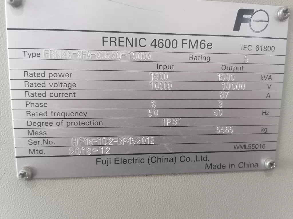
FRENIC 4600 FM6e

1. Causes and Analysis of PWM Fiber Optic Connection Errors

1.1 Fiber Optic Connection Issues

PWM (Pulse Width Modulation) fiber optic connections are a critical path for signal transmission between the inverter’s internal control system and external devices. When there is instability or loss of the fiber optic connection, the inverter may fail to receive or transmit control signals correctly. Common fiber optic connection issues include:

  • Loose or Damaged Fiber Optic Connectors: Over time, after prolonged use or idle periods, the fiber optic connectors may become loose, oxidized, or physically damaged, resulting in unstable signal transmission.
  • Pollution or Obstruction of Fiber Optic Connectors: Dust, oil, and other substances can accumulate on fiber optic connectors, impacting the quality of signal transmission, which may lead to connection errors.
  • Electromagnetic Interference (EMI): In environments with strong electromagnetic interference, signals can be disrupted, causing errors in fiber optic communication.

When these issues occur, the inverter’s signal transmission is interrupted or distorted, preventing the control system from regulating the motor’s operation properly.
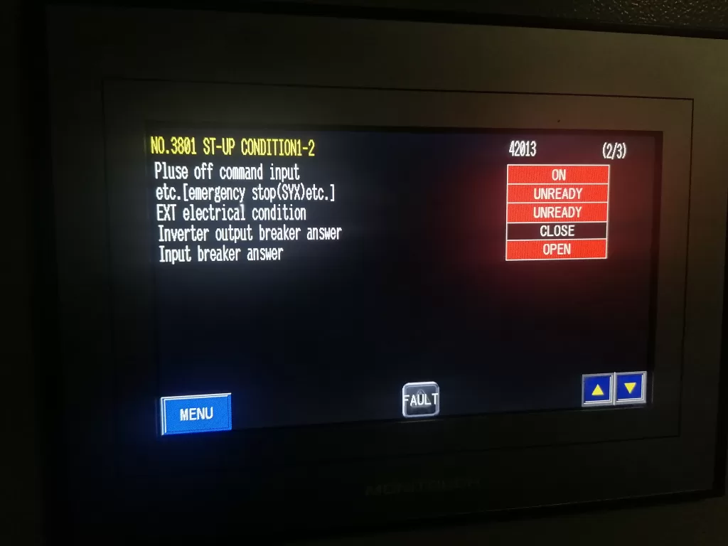
Inverter output breaker answer

1.2 Triggering Mechanism of Motor Overload

When a fiber optic connection error occurs, the inverter may fail to obtain accurate motor status information or adjust the output frequency correctly. Without proper regulation of the motor load and operating conditions, the inverter may generate unstable power or current output, resulting in motor overload.

  • Loss of Control Signals: With a fiber optic connection error, the inverter cannot receive feedback from the motor, leading to an inability to regulate the motor’s load properly, which causes excessive current and triggers the overload alarm.
  • Frequency Regulation Failure: If the inverter cannot correctly adjust the output frequency due to fiber optic signal loss, the motor may run at non-optimal settings for extended periods, leading to overload.
  • Excessive Inrush Current During Startup: Without proper communication through fiber optic signals, the inverter may fail to handle the large inrush current during motor startup, resulting in an overload fault.

2. Correlation Between Fiber Optic Connection Errors and Motor Overload

From the fault diagnosis experience, PWM fiber optic connection errors and motor overload are closely related. Fiber optic connection errors typically serve as the root cause, while motor overload is a direct consequence of this issue.

  1. Protection Mechanism Triggered by Signal Loss: If the inverter cannot obtain motor feedback due to a fiber optic connection issue, the system may enter a “protection mode” and activate overload protection. This prevents the system from operating normally, resulting in excessive current flowing through the motor and triggering an overload alarm.
  2. Incorrect Motor Load Detection: Without proper fiber optic feedback, the inverter may misinterpret the motor load, causing the system to falsely detect an overload condition and activate the protection mechanism unnecessarily.
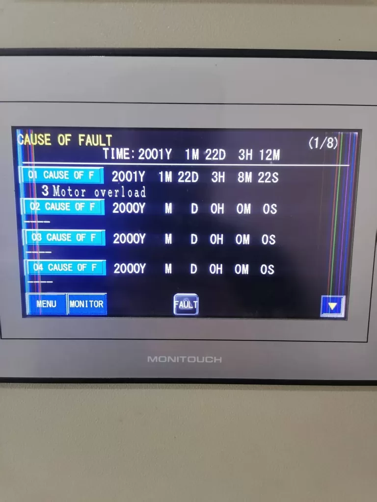
Motor overload

3. Fault Analysis and Troubleshooting Steps

3.1 Power Off and Reset

Since a fiber optic connection issue can trigger the inverter’s internal protection mechanism, the first step is to perform a power off and reset operation. Disconnect the power, ensuring the system is completely powered off, then execute the inverter’s reset procedure to clear all alarm information.

3.2 Inspect Fiber Optic Connections

After the reset, the next step is to inspect the PWM fiber optic connections for any issues such as looseness, damage, or contamination. Prolonged use or idle periods may cause degradation in fiber optic connectors. Follow these steps to check the fiber optic connections:

  • Check the Connectors and Cables: Ensure that the fiber optic connectors are secure, free from oxidation, and that the cables are not damaged or broken.
  • Clean the Fiber Optic Connectors: Use cleaning tools to remove any dust or oil contaminants from the fiber optic connectors to ensure proper signal transmission.
  • Replace Fiber Optic Cables: If the fiber optic cables are damaged, they should be replaced immediately.

3.3 Inspect the Motor and Load

Once the fiber optic connection issue is resolved, inspect the motor and load for potential faults. Motor overload may also be caused by mechanical issues with the motor or abnormal load conditions. Check the motor’s condition and verify that the load is within normal operating limits:

  • Check the Motor Condition: Use a multimeter to test the motor’s winding resistance to ensure there are no short circuits or grounding faults.
  • Check the Load Equipment: Ensure that the load connected to the motor is not too heavy or jammed. Examine the mechanical components for signs of resistance or abnormal wear.

3.4 Check Inverter Control Parameters

If no issues are found with the motor or load, the next step is to check the inverter’s control parameters. Ensure that the overload protection and current limit settings on the inverter are correct and aligned with the motor’s rated specifications:

  • Adjust Overload Protection Settings: Modify the inverter’s overload protection parameters according to the motor’s rated power and load requirements to avoid overly sensitive triggering of the protection mechanism.
  • Set Frequency Limits: Verify that the inverter’s frequency settings are within the motor’s maximum operating frequency range to prevent overload conditions caused by excessive frequency.

3.5 Inspect Current Detection Circuit

Finally, check the inverter’s current detection circuit for functionality. A faulty current sensor or circuit could lead to incorrect readings, resulting in false overload alarms. Use the inverter’s diagnostic functions to inspect the current sensor and replace or repair it as needed.
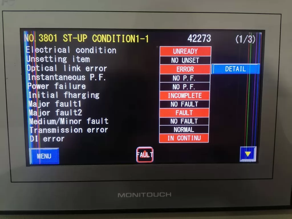
Optical link error

4. Conclusion

The PWM fiber optic connection error and motor overload fault in the Fuji FRENIC 4600 series inverter are often interrelated, with the fiber optic connection issue serving as the root cause and the motor overload being a direct consequence. Fiber optic connection errors result in signal loss, which prevents the inverter from properly regulating the motor load and frequency, triggering an overload alarm. By systematically checking fiber optic connections, motor conditions, inverter parameters, and current detection circuits, these faults can be resolved, and the system can return to normal operation. Throughout the troubleshooting process, it is essential to prioritize high-voltage safety and follow proper electrical safety protocols to ensure the safety of both the equipment and personnel.

Posted on Leave a comment

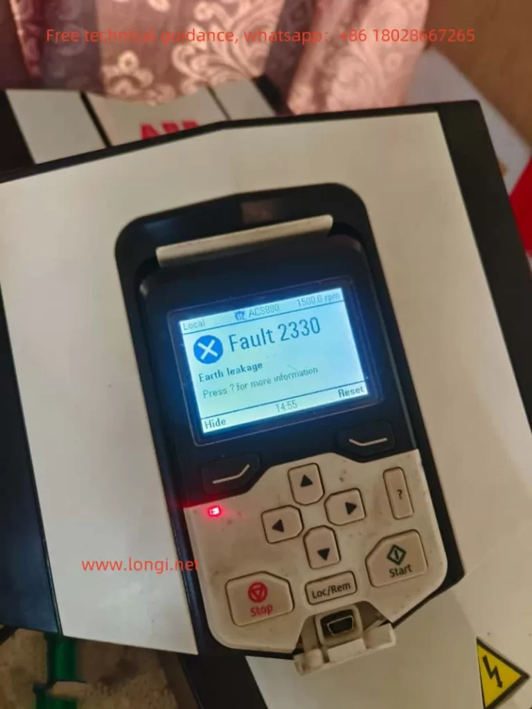
Analysis and Solution for Ground Fault (fault 2330) in ABB ACS880 Inverter

I. Introduction

The ABB ACS880 inverter is widely used in industrial control systems due to its high performance and reliability. However, during practical applications, the inverter may encounter various faults, among which the ground fault (fault 2330) is a relatively common and severe one. This article provides an in-depth analysis of the mechanism behind the ground fault in ABB ACS880 inverters and proposes corresponding solutions.

II. Mechanism Analysis of Ground Fault in ABB ACS880 Inverter

1. The Nature of Ground Fault

A ground fault in the ABB ACS880 inverter manifests as the fault code 2330, essentially a serious overcurrent fault. When the inverter detects grounding issues in the motor or motor cables, such as three-phase imbalance, it triggers the ground fault protection mechanism. This fault can not only damage IGBT modules or drive circuits but also have a significant impact on the entire electrical system.

2. Causes of Ground Fault

(1) Damaged Motor or Motor Cables: Insulation damage, aging, or loose connections in motor windings or cables can lead to current leakage to ground, triggering a ground fault.
(2) External Factors: External factors such as lightning strikes or overvoltage can also cause insulation breakdown in motors or cables, resulting in ground faults.
(3) Hardware Faults: Faults in IGBT modules or drive circuits can also cause the inverter to falsely report a ground fault.

3. Detection Principle of Ground Fault

The ABB ACS880 inverter detects ground faults by monitoring the imbalance of motor currents. When the imbalance of the three-phase currents exceeds the preset value, the inverter identifies it as a ground fault and immediately stops output to protect the motor and the inverter itself.

III. General Solutions for Ground Fault

1. Hardware Inspection and Repair

(1) Check Motor and Cables: First, inspect the motor and cables for insulation damage, aging, or loose connections. If any issues are found, repair or replace them promptly.
(2) Check Inverter Hardware: Inspect the IGBT modules, drive circuits, and other components inside the inverter to confirm the absence of damage or abnormalities. If necessary, contact professional technicians for repairs.

2. Parameter Adjustment and Testing

After confirming that the hardware is functioning correctly, attempt to resolve the issue by adjusting relevant inverter parameters. However, it should be noted that parameter adjustments should be made under the guidance of professional technicians to avoid causing larger faults due to misoperation.

IV. Shielding Method for Ground Fault in ACS880 Inverter under Normal Hardware Conditions

1. Setting of Parameter 31.20

According to the user manual of the ABB ACS880 inverter, parameter 31.20 is used to select the inverter’s response when a ground fault is detected. Setting it to 0 can shield the ground fault alarm. However, it should be noted that shielding the ground fault alarm is only applicable when the hardware is confirmed to be functioning correctly. If there are hardware issues and the alarm is blindly shielded, it may lead to further damage to the inverter or motor.

2. Operating Steps

(1) Enter the Parameter Settings Interface: Access the parameter settings interface through the inverter’s control panel or professional debugging software.
(2) Locate Parameter 31.20: Find parameter 31.20 in the parameter list and set its value to 0.
(3) Save Settings and Restart Inverter: After setting is complete, save the parameter settings and restart the inverter to make the changes effective.

3. Precautions

(1) Confirm Hardware Functionality: Before shielding the ground fault alarm, ensure that the motor, cables, and inverter hardware are all functioning correctly.
(2) Monitor Operating Status: After shielding the alarm, closely monitor the inverter’s operating status and promptly address any abnormalities.
(3) Regular Maintenance Checks: Regularly perform maintenance checks on the inverter to detect and address potential issues in a timely manner, preventing faults from occurring.

V. Conclusion

When the ABB ACS880 inverter encounters a ground fault (fault 2330), hardware inspection and repair should be carried out first, followed by consideration of resolving the issue through parameter adjustments. Under normal hardware conditions, the ground fault alarm can be shielded by setting parameter 31.20 to 0. However, it should be noted that shielding the alarm is only applicable when the hardware is confirmed to be functioning correctly, and the inverter’s operating status should be closely monitored to avoid causing larger faults due to misoperation or neglecting potential issues. Through scientific and rational fault analysis and solutions, the stable operation and extended service life of the ABB ACS880 inverter can be effectively ensured.

Posted on Leave a comment

Operation Guide for Colran Inverter CV800 Series User Manual

I. Introduction to the Operation Panel Functions and Initialization Settings

The Colran Inverter CV800 series features an intuitive operation panel with clear buttons and a display screen, facilitating various settings and monitoring tasks for users. The operation panel primarily includes run/stop keys, frequency adjustment keys (▲/▼), function keys, and a display screen.

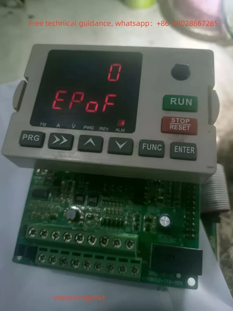
EPOF Fault

Parameter Initialization:

  • Press the function key to enter the parameter setting interface.
  • Use the ▲/▼ keys to select the F8.03 parameter (Parameter Initialization).
  • Press the run/stop key to set F8.03 to 1, which will restore the factory settings, and all user parameters will be reset to their factory defaults.

Setting and Removing Password:

  • Password Setting: Set through the F0.23 parameter (User Password). Set any non-zero number, which will take effect after waiting for 3 minutes or a power cycle.
  • Password Removal: Set the F0.23 parameter value to 0 to remove the password.

Setting Parameter Access Restrictions:

  • The CV800 series inverters provide parameter access restriction functions, but the specific implementation method is not explicitly mentioned in the manual. Generally speaking, parameter access restrictions can be indirectly achieved by setting a password, allowing only users who know the password to modify critical parameters.

II. Terminal Forward/Reverse Control and External Potentiometer Given Frequency Speed Regulation

Terminal Forward/Reverse Control:

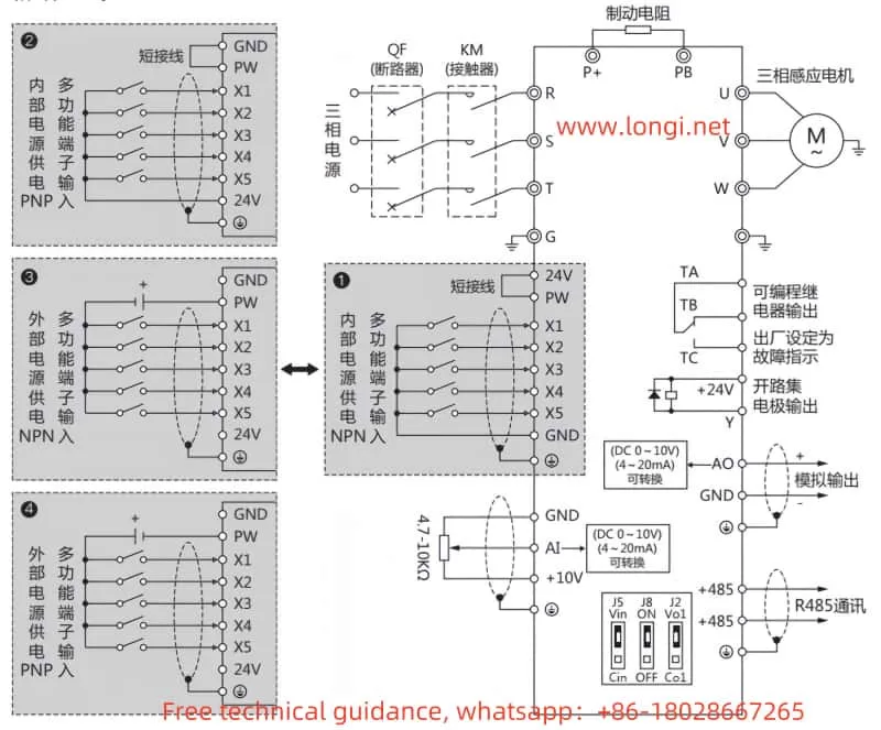
  • Wiring:
    • Connect the forward control signal to the X1 terminal (Forward Control, FWD).
    • Connect the reverse control signal to the X2 terminal (Reverse Control, REV).
    • Ensure the common terminal (COM) is correctly connected.
  • Parameter Setting:
    • Set F0.02 parameter (Operation Command Channel Selection) to 1 (Terminal Operation Command Channel).
    • Set F2.13 parameter (Input Terminal X1 Function) to 3 (Forward Control).
    • Set F2.14 parameter (Input Terminal X2 Function) to 4 (Reverse Control).

External Potentiometer Given Frequency Speed Regulation:

  • Wiring:
    • Connect the output terminal of the external potentiometer to the AI terminal (Analog Input).
    • Ensure the common terminal (COM) is correctly connected.
  • Parameter Setting:
    • Set F0.03 parameter (Frequency Given Selection) to 0 (Panel Potentiometer) or 3 (AI Analog Given).
    • Set F2.00 (AI Input Lower Limit Voltage) and F2.01 (AI Input Upper Limit Voltage) as needed.
    • F2.02 (AI Lower Limit Correspondence Setting) and F2.03 (AI Upper Limit Correspondence Setting) are used to set the correspondence between AI input and output frequency.
CV800 Terminal Wiring Diagram

III. Fault Codes and Solutions

The CV800 series inverters provide a wealth of fault codes to help users quickly locate and resolve issues. Below are some common fault codes, their meanings, and solutions:

  • E0C1: Overcurrent During Acceleration.
    • Meaning: The current during acceleration exceeds the allowable limit.
    • Solution: Extend the acceleration time, check if the load is too heavy, or select an inverter with higher power.
  • E0C2: Overcurrent During Deceleration.
    • Meaning: The current during deceleration exceeds the allowable limit.
    • Solution: Extend the deceleration time and check for sudden load changes.
  • EHU1: Overvoltage During Acceleration.
    • Meaning: The voltage during acceleration exceeds the allowable limit.
    • Solution: Check for abnormal input power or set the DC braking function.
  • EPOF: Dual CPU Communication Fault.
    • Meaning: Internal CPU communication within the inverter is abnormal.
    • Solution: Restart the inverter. If the problem persists, contact the manufacturer for repair.
  • E-OH: Heatsink Overheated.
    • Meaning: The temperature of the inverter’s heatsink is too high.
    • Solution: Check if the ambient temperature is too high, clean the air duct, or replace the fan.

IV. Conclusion

The Colran Inverter CV800 series, with its rich functionality and stable performance, has found widespread application in the industrial automation field. This operation guide enables users to easily master the basic operation, parameter settings, terminal wiring, and troubleshooting methods of the inverter, ensuring its normal operation and efficient use. Meanwhile, users should regularly check the working status of the inverter, promptly detect and resolve issues to guarantee the continuous and stable operation of the production line. In practical applications, users should also perform personalized settings based on specific needs to fully leverage the performance advantages of the inverter.

Posted on Leave a comment

ADSEN Variable Frequency Drive ADS-V Series User Manual Operation Guide

I. Introduction to Operation Panel Functions

The operation panel of the ADSEN Variable Frequency Drive (VFD) ADS-V series serves as a crucial interface for user interaction with the device. The panel typically includes multiple function keys and a display screen, allowing users to perform operations such as start, stop, frequency setting, and parameter modification. The main function keys on the panel include:

  • Run Key: Starts the VFD operation.
  • Stop/Reset Key: Stops the VFD operation or resets it after a fault occurs.
  • Forward/Reverse Switch Key: Switches the running direction of the VFD.
  • Set Key: Enters the parameter setting mode.
  • Display/Shift Key: Cycles through different parameters such as output frequency, current, temperature, etc., in display mode.
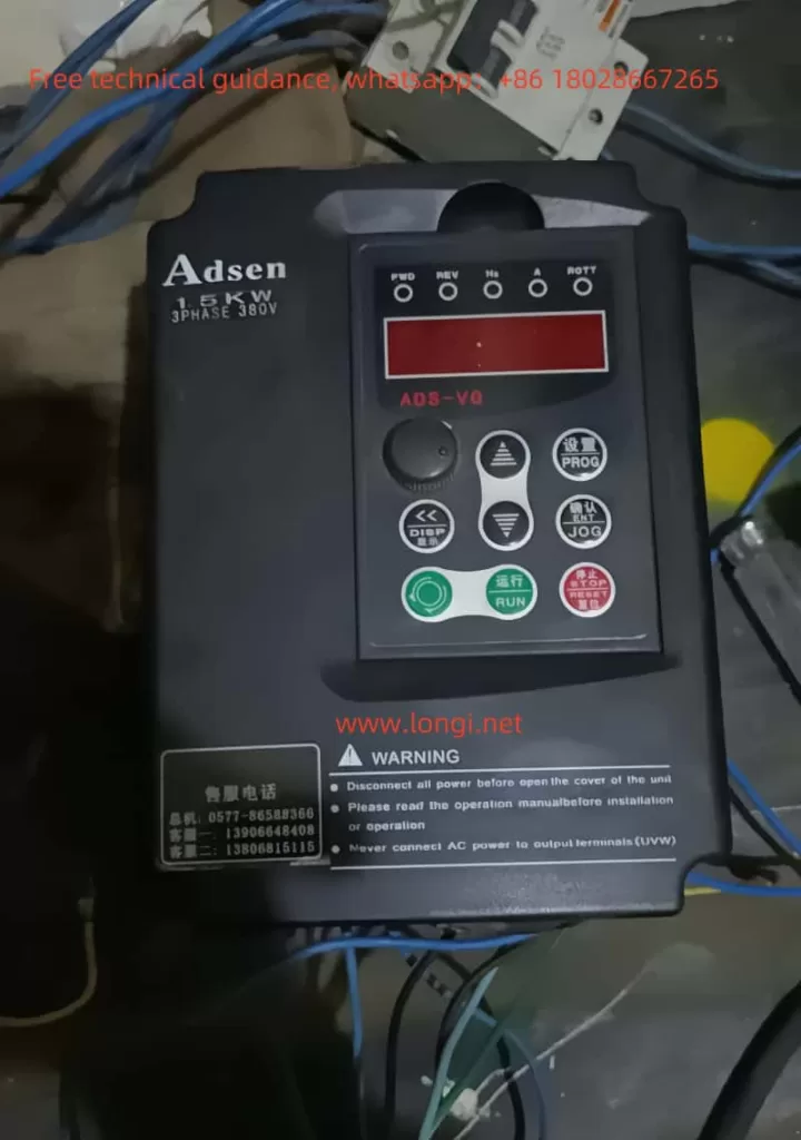
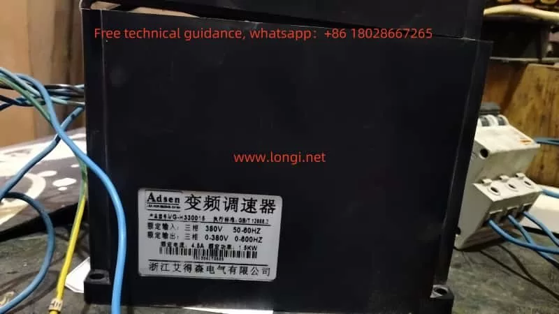
Front image of ADSEN VFD

1.1 Initializing Parameters (Restoring Factory Settings)

To restore all parameters of the VFD to factory settings, users can follow these steps:

  1. Press the “Set” key to display “Pr000”.
  2. Use the “Increase” or “Decrease” key to adjust to “Pr013” (parameter reset) and set the value to “01”.
  3. Press the “Confirm” key (usually the “Jog” key) to confirm the reset.
  4. At this point, the VFD will restore to factory settings, and all user-set parameters will be cleared.

1.2 Setting and Removing a Password

To protect the parameter security of the VFD, users can set a password to prevent unauthorized access. The specific steps are as follows:

  1. Enter the parameter setting mode and locate “Pr000” (parameter lock).
  2. Set the value to “1” to enable password protection.
  3. To remove the password, set it to “0”.

1.3 Setting Parameter Access Restrictions

After setting the parameter lock in “Pr000”, users can prevent others from modifying the parameters. A setting of “0” indicates invalid, while “1” indicates valid. Users must unlock before modifying parameters.

II. External Terminal Forward/Reverse Control and External Potentiometer Frequency Speed Adjustment

2.1 External Terminal Forward/Reverse Control

To achieve external terminal forward/reverse control, users need to wire the following terminals:

  • X1 Terminal: Run control signal.
  • X2 Terminal: Reverse control signal.
  • X3 Terminal: Stop control signal.

Parameter Settings:

  1. Set “Pr001” to “1” to select external terminal control.
  2. Set “Pr044” to “02” to assign X1 as run.
  3. Set “Pr045” to “03” to assign X2 as reverse.
  4. X3 terminal can be set as stop.

2.2 External Potentiometer Frequency Speed Adjustment

Connect the external potentiometer to the following terminals:

  • FV Terminal: Frequency setting input.
  • GND Terminal: Ground.

Parameter Settings:

  1. Set “Pr001” to “1” to select external terminal control.
  2. Set “Pr002” to “1” to select external potentiometer for frequency setting.
  3. Set “Pr072” to the desired maximum frequency (e.g., 50Hz).

With these settings, users can adjust the output frequency of the VFD using an external potentiometer.

ADSEN VFD physical image

III. Fault Codes and Troubleshooting

The ADSEN VFD ADS-V series provides multiple fault protection functions. Common fault codes and their troubleshooting methods are as follows:

3.1 Common Fault Codes

  • OU-1: Overvoltage during acceleration
    • Troubleshooting: Check the grid voltage and extend the acceleration/deceleration time.
  • OU-2: Overvoltage during deceleration
    • Troubleshooting: Extend the deceleration time or install a braking resistor.
  • FB: Fuse blown
    • Troubleshooting: Send for factory repair.
  • OH: VFD overheat
    • Troubleshooting: Check if the fan is blocked and ensure the ambient temperature is normal.
  • OL-1: VFD overcurrent or overload
    • Troubleshooting: Check if the load is too large and reset the parameters.
  • LV: Undervoltage
    • Troubleshooting: Check if the input voltage is normal.

3.2 Fault Handling

In the event of a fault, immediately press the stop key and record the fault code. Users should refer to the manual for corresponding checks and troubleshooting based on the fault code. If the fault cannot be resolved, contact professional technicians for repair.

IV. Summary

The user manual of the ADSEN VFD ADS-V series provides a detailed operation guide. Users should be familiar with the functions of the operation panel and fault troubleshooting methods during daily operations. By properly setting parameters and conducting effective maintenance checks, the normal operation of the VFD can be ensured, and its service life can be extended. In practical applications, if any issues are encountered, users should refer to the manual for resolution or contact professionals for support.

Posted on Leave a comment

Operation Guide for Ruishen Inverter RCP900 Series User Manual

I. Introduction to Operation Panel Functions and Parameter Initialization

The Ruishen Inverter RCP900 series is equipped with an intuitive and user-friendly operation panel, which integrates a data display area, command source indicators, forward/reverse indicators, and various other functions. Through this panel, users can easily perform parameter settings, working status monitoring, operation control, and other operations of the inverter.

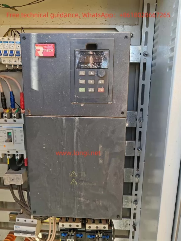
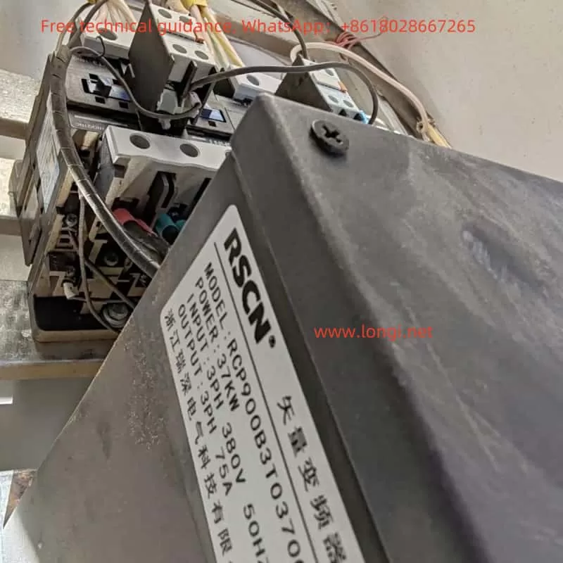
RCP900正面图片

Parameter Initialization:

Before using the RCP900 series inverter, it is sometimes necessary to initialize the parameters to restore the factory settings. This can be achieved by setting the function code PP-01. Setting PP-01 to 1 will restore the inverter’s factory parameters (excluding motor parameters). This step is particularly important for resolving inverter faults caused by incorrect parameter settings.

Password Setting and Removal:

To protect the inverter settings from unauthorized changes, the RCP900 series inverter supports password protection. Users can set a password by configuring the function code PP-00. To remove the password, simply set PP-00 to 0. The password protection feature effectively prevents unauthorized operations and ensures the safety and stability of the inverter’s operation.

Parameter Access Restriction:

In addition to password protection, the RCP900 series inverter also supports parameter access restriction functionality. Users can select which parameter groups or specific parameters can be accessed and modified by configuring the function codes PP-03 and PP-04. This feature allows users to flexibly control access permissions to the inverter parameters based on actual needs, enhancing the security of device management.

RCP900 Side Image

II. Terminal Forward/Reverse Control and External Potentiometer Speed Regulation

Terminal Forward/Reverse Control:

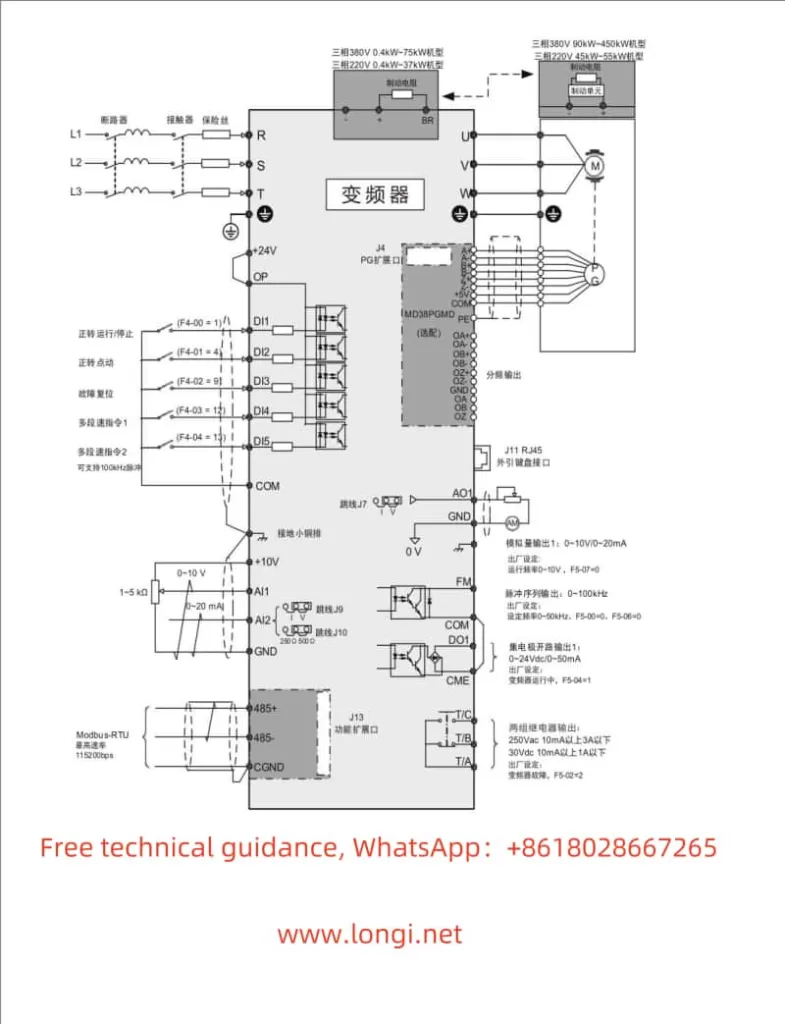
The RCP900 series inverter supports forward/reverse control of the motor through terminals. The specific wiring method is as follows: Connect the forward control signal to the DI1 terminal, the reverse control signal to the DI2 terminal, and the common terminal to the COM terminal. In terms of parameter settings, it is necessary to set P0-02 (Run Command Selection) to 1 (Terminal Command), P4-00 (DI1 Terminal Function Selection) to 1 (Forward Run), and P4-01 (DI2 Terminal Function Selection) to 2 (Reverse Run). After completing these settings, the motor’s forward/reverse control can be achieved by controlling the electrical level status of the DI1 and DI2 terminals.

External Potentiometer Speed Regulation:

The RCP900 series inverter also supports speed regulation through an external potentiometer. The specific wiring method is as follows: Connect the output end of the external potentiometer to the AI1 terminal and the GND terminal to the inverter’s GND terminal. In terms of parameter settings, it is necessary to set P0-03 (Main Frequency Command Input Selection) to 4 (AI3 Panel Potentiometer). After completing these settings, the motor speed can be adjusted by adjusting the resistance value of the external potentiometer.

RCP900 Standard Wiring Diagram

III. Fault Code Meaning Analysis and Troubleshooting

During operation, the RCP900 series inverter may encounter various faults. When a fault occurs, the inverter will display the corresponding fault code. Below are some common fault codes, their meanings, and troubleshooting methods:

  • Err02: Acceleration Overcurrent. Possible causes include grounding or short circuit in the output circuit, incorrect motor parameter settings, etc. Solutions include troubleshooting peripheral issues, performing motor parameter identification, etc.
  • Err03: Deceleration Overcurrent. Possible causes are similar to those of acceleration overcurrent. Solutions also include troubleshooting peripheral issues, increasing deceleration time, etc.
  • Err05: Acceleration Overvoltage. Possible causes include high input voltage, short acceleration time, etc. Solutions include adjusting the input voltage, increasing the acceleration time, etc.
  • Err14: IGBT Overheat. Possible causes include high ambient temperature, fan failure, etc. Solutions include lowering the ambient temperature, replacing the fan, etc.

For the above fault codes, users can adopt corresponding solutions based on the inverter’s display information, combined with fault phenomena and possible causes. If the issue cannot be resolved, it is recommended to contact Ruishen Inverter’s technical support personnel or professional maintenance personnel for assistance.

IV. Conclusion

The Ruishen Inverter RCP900 series user manual provides a detailed operation guide, including operation panel function introduction, parameter initialization, password setting and removal, parameter access restriction, terminal forward/reverse control, external potentiometer speed regulation, fault code meaning analysis, troubleshooting methods, and other content. By carefully reading and understanding the user manual, users can better master the inverter’s usage methods and maintenance skills, ensuring the normal operation of the equipment and extending its service life. At the same time, users should flexibly utilize the inverter’s various functions based on actual needs to achieve more efficient and stable motor control.

Posted on Leave a comment

HOLIP Frequency Converter HLP-SV Series User Manual Operation Guide

I. Introduction to Operation Panel Functions and Parameter Settings

Introduction to Operation Panel Functions

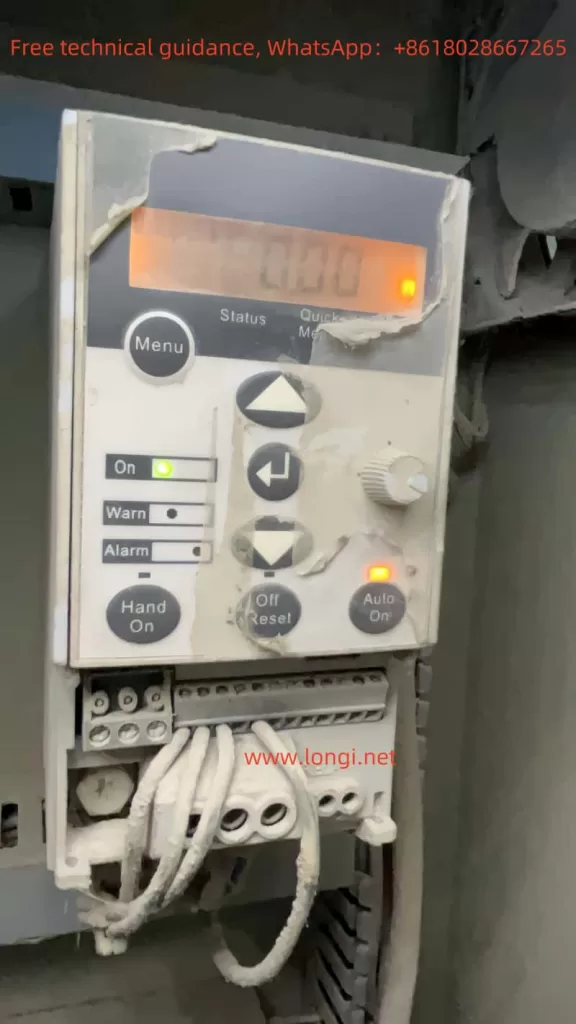
The operation panel (LCP operator) of the HOLIP HLP-SV series frequency converter provides an intuitive interface for users to set parameters and monitor operations. The operation panel mainly includes a display screen, function keys, navigation keys, potentiometers, and indicators. The display screen shows current parameters, converter status, and other data. The function keys are used to select menus and execute operations. The navigation keys allow for setting, switching, and changing operations within parameter groups, parameters, and parameter internals. The potentiometer is used to adjust motor speed in manual mode. The indicators show the operating status of the converter, such as power access, warnings, and alarms.

HLP-SV power on standby state

Initializing Parameters

To initialize the converter parameters, users can set parameter 14-22 to 2 to restore the converter to factory defaults. This operation will reset all parameters except parameters 15-03 (operating hours counter), 15-04 (overheat count), and 15-05 (overvoltage count) to their factory default values. Before performing this operation, ensure that important parameter settings have been backed up.

Setting and Removing Passwords

To prevent unauthorized parameter modifications, users can set a password. Parameter 0-60 can be used to set a password for the main menu, with a range of 0-999. After setting the password, only by entering the correct password can protected parameters be modified. To remove the password, simply set parameter 0-60 to 0.

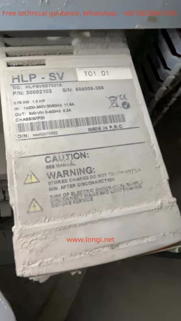
Physical image on the right side of HLP-SV

Setting Parameter Access Restrictions

The HOLIP frequency converter provides parameter access restriction functions. Users can control the activation and editing permissions of different menus by setting parameters 0-10, 0-11, and 0-12. For example, setting parameter 0-10 to 1 or 2 can activate Menu 1 or Menu 2, respectively. Setting parameter 0-11 to 1 or 2 allows editing of Menu 1 or Menu 2, respectively. Setting parameter 0-12 to 20 enables parameter association between Menu 1 and Menu 2, ensuring that parameters that cannot be changed during operation can be synchronized between the two menus.

II. Terminal Forward/Reverse Control and External Potentiometer Speed Regulation

Terminal Forward/Reverse Control

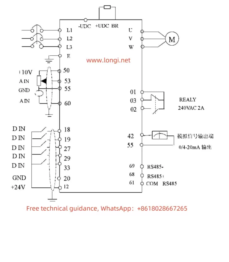
To achieve motor forward/reverse control, users need to connect external control signals to the digital input terminals of the converter. Typically, terminals 18 and 19 are used to control motor forward and reverse, respectively. The specific wiring method is as follows:

  • Forward: Connect the external control signal to terminal 18 (DI1) and the common terminal (COM).
  • Reverse: Connect the external control signal to terminal 19 (DI2) and the common terminal (COM).

Additionally, set the functions of terminals 18 and 19 to “Start” and “Reverse” in parameters 5-10 and 5-11, respectively. Also, set the motor rotation direction to “Bidirectional” in parameter 4-10.

External Potentiometer Speed Regulation

External potentiometer speed regulation is a commonly used speed control method. Users can change the motor speed by rotating the potentiometer. The specific wiring method is as follows:

  • Connect one end of the external potentiometer to the +10V power terminal of the converter (e.g., terminal 50).
  • Connect the other end of the external potentiometer to the analog input terminal of the converter (e.g., terminal 53) and ground (GND).

Then, select “Voltage Signal” as the input signal type for terminal 53 in parameter 6-19, and set the source of Reference Value 1 to “LCP Potentiometer” in parameter 3-15. By rotating the external potentiometer, users can adjust the motor speed in real-time.

HOLIP-SV standard wiring diagram

III. Fault Codes and Their Solutions

The HOLIP HLP-SV series frequency converter has comprehensive protection functions. When a fault occurs, the converter will display the corresponding fault code. The following are some common fault codes, their meanings, and solutions:

  • W/A 2: Signal Float Zero Fault
    • Meaning: This fault occurs when the converter detects that the float zero value of terminal 53 or 60 is less than 50% of the set value.
    • Solution: Check if the signal line connection is normal and ensure a stable signal source.
  • W/A 4: Power Phase Loss
    • Meaning: There is a phase loss or excessive voltage imbalance at the power supply terminal.
    • Solution: Check the power input line and power supply voltage for normalcy.
  • W/A 7: Overvoltage
    • Meaning: The intermediate circuit voltage (DC) exceeds the converter’s overvoltage limit.
    • Solution: Check if the power supply voltage is too high, connect a braking resistor, or activate “Braking Function/Overvoltage Control” in parameter group 2.
  • W/A 9: Converter Overload
    • Meaning: The converter’s electronic thermal protection indicates that the converter is about to disconnect due to overload.
    • Solution: Check if the mechanical system is overloaded, adjust the load, or increase the converter capacity.
  • W/A 10: Motor Overheat
    • Meaning: The electronic thermal relay (ETR) protection device indicates motor overheat.
    • Solution: Check the motor load and motor parameter settings for correctness, reduce the load, or improve the cooling conditions.
  • A 16: Output Short Circuit
    • Meaning: There is a short circuit in the motor terminal or motor.
    • Solution: Check if the motor insulation is damaged and eliminate the short circuit fault.

The above are only some fault codes and their solutions. Users can refer to the fault code table in the converter user manual for troubleshooting other faults encountered during use.

IV. Conclusion

The HOLIP HLP-SV series user manual provides detailed operation guides and troubleshooting methods for users. By familiarizing with the functions of the operation panel and parameter setting methods, users can easily initialize the converter, set passwords, restrict parameter access, achieve forward/reverse control and external potentiometer speed regulation, and more. At the same time, understanding common fault codes and their solutions helps users quickly troubleshoot and resolve converter faults, ensuring normal equipment operation.

Posted on Leave a comment

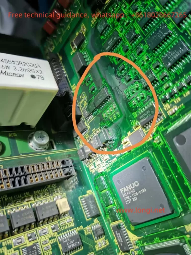
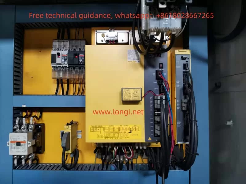
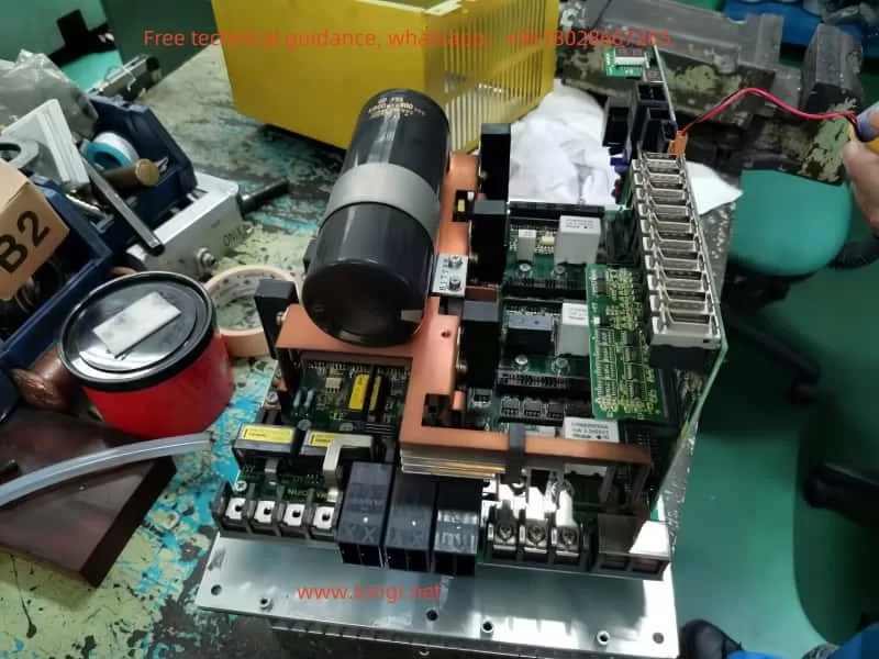
FANUC Servo Drive βISVSP A06B Maintenance Guide: Troubleshooting No Display Issues


FANUC servo drives, specifically the βISVSP A06B series, are widely used in various automated equipment, providing efficient and precise motor control. However, in practical use, various faults may arise, with one of the most common being the lack of display. A non-functional display is often caused by power issues, control circuit problems, or hardware malfunctions. This article explores the maintenance approach for resolving no display issues in FANUC servo drives, focusing on troubleshooting steps and solutions.

I. Fault Phenomenon: No Display

The no display fault in FANUC servo drives refers to a situation where the device powers on, but the panel displays no information. The indicator lights might be completely off, or the screen may be unresponsive, suggesting that there could be problems with the control circuits, display module, or power supply module inside the drive. If not addressed in a timely manner, this issue could prevent the device from starting or executing control instructions, which can negatively impact production efficiency.

II. Troubleshooting Approach

When encountering a no display issue in a servo drive, it’s essential to systematically check the device. Below are the common troubleshooting steps:

1. Check Power Supply Input

The first step is to verify if the power supply to the servo drive is functioning correctly. Power is the foundation for all electronic devices, and any instability or interruption in the power supply can prevent the drive from functioning properly.

  • Check the Power Voltage: Use a multimeter to check the voltage at the input terminals of the servo drive, confirming that it falls within the specified range. The FANUC servo drive typically requires a three-phase AC input voltage within a certain range.
  • Check Power Connections: Verify that the power supply cables are correctly connected and not damaged or disconnected. Poor power contact can lead to unstable voltage supply, which can result in no display issues.

2. Check Fuses and Circuit Breakers

Servo drives are equipped with fuses or circuit breakers to prevent damage from excessive current. If a fuse blows or the circuit breaker trips, the device will fail to operate properly.

  • Check the Fuse: Open the servo drive and inspect the fuses in the power section. If the fuse is blown, replace it with one of the same rating.
  • Check the Circuit Breaker: Some servo drives come with an internal circuit breaker that trips in case of voltage abnormalities or overcurrent. If the circuit breaker has tripped, reset it manually.

3. Check the Main Control Circuit

If the power supply is fine, the next step is to inspect the servo drive’s main control circuit. The control circuit acts as the brain of the servo drive, and any malfunction in this area could result in a non-responsive display.

  • Check the Control Chip: The control chip is usually located centrally on the circuit board and is responsible for processing input signals and controlling the operation of the drive. Look for signs of overheating, burning, or damage around the chip. Use an oscilloscope or multimeter to check the power supply voltage and signal output of the chip to ensure it’s functioning properly.
  • Check Circuit Connections: The circuit board in the servo drive is connected to various modules via connectors. Check if any connectors are loose or disconnected, as poor connections can prevent signals from transmitting correctly.

4. Check the Display Module and Signal Transmission

The display module is responsible for showing system status information to the operator. If the display module fails, it could lead to a no display situation.

  • Check the Display Screen: Inspect the power supply input terminals and signal transmission lines to the display screen to ensure they are properly connected. If the display module itself is faulty, it may need to be replaced.
  • Check Signal Transmission: If the display module appears intact, the issue could lie with the signal transmission. Inspect the signal lines between the main control board and the display module to ensure that signals are properly transmitted.

5. Check Capacitors and Power Filtering Circuits

Capacitors and filtering circuits help stabilize the voltage supply, especially for high-frequency currents. If the capacitors are damaged, the power supply could become unstable, affecting the drive’s operation.

  • Check the Capacitors: Look for signs of bulging, leakage, or aging in the capacitors. If a capacitor is faulty, it should be replaced with one of the same model.
  • Check the Filtering Circuits: The components in the filtering circuits may also be damaged, which can cause unstable voltage output. Inspect these components and replace them as necessary.

III. Common Fault Analysis and Solutions

1. Unstable Power Supply Leading to No Display

An unstable power supply voltage can prevent the drive from starting properly. In this case, check the stability of the power supply and ensure the voltage is within the specified range. If issues are found with the power supply, it may be necessary to replace the power module or reconnect the power supply.

2. Control Circuit Malfunction

A malfunctioning control circuit can prevent the system from starting or lead to a no display issue. Typically, this fault requires replacing damaged components. Commonly damaged components include control chips, integrated circuits, and resistors.

3. Display Module Failure

If the display module itself is faulty, it could be due to issues with the backlight, circuit board, or the display screen. Inspect the power input terminals and signal transmission lines to confirm the issue. If the display screen is damaged, replacing the display module will likely resolve the problem.

4. Capacitor or Filtering Circuit Issues

Damaged capacitors can cause unstable power, affecting the drive’s operation. Replacing faulty capacitors or repairing the filtering circuits should solve this issue.

IV. Conclusion

The no display issue in FANUC servo drives βISVSP A06B series is typically related to power problems, control circuit failures, or display module malfunctions. Through systematic troubleshooting and careful inspection, the problem can usually be pinpointed and resolved. During maintenance, special attention should be paid to power stability, circuit connections, and the condition of critical components. For more complex issues, professional diagnostic tools may be required, and damaged components should be replaced to restore the device to normal operation. Timely and effective maintenance ensures the long-term stability and performance of FANUC servo drives, helping to maintain production efficiency.

Posted on Leave a comment

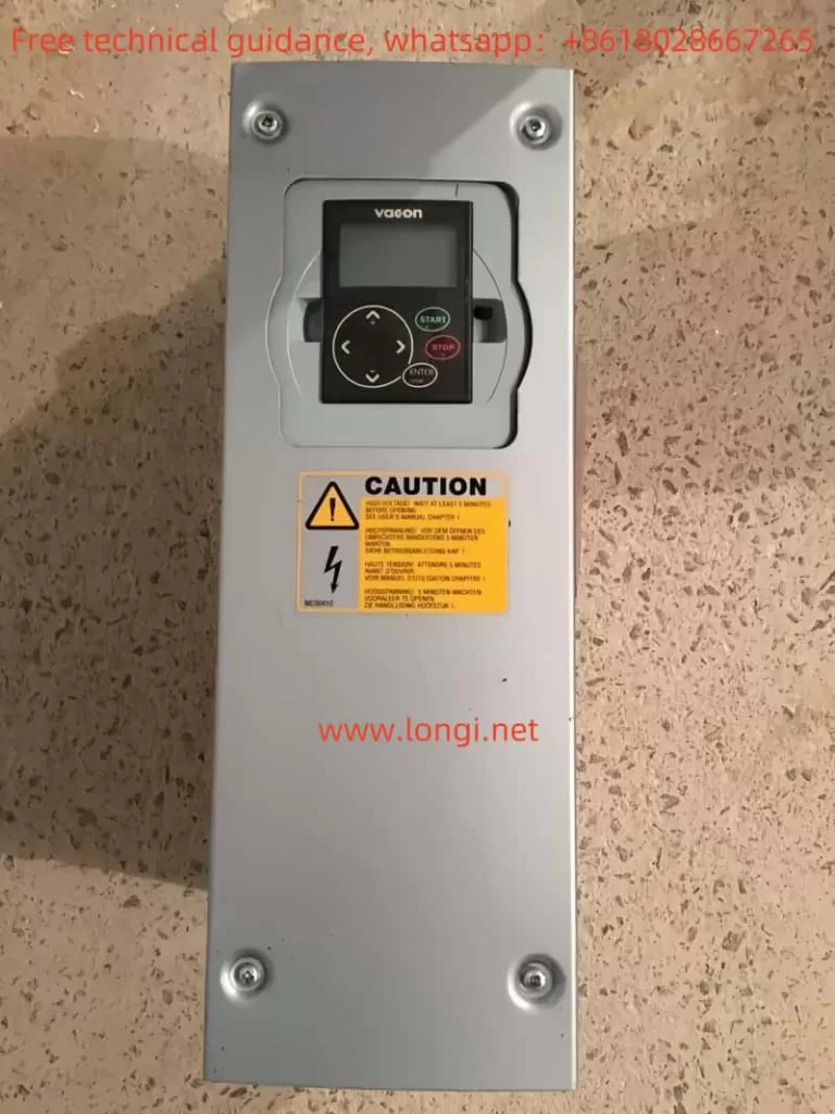
User Manual Guide for Vacon NXS_NXP Series Inverters

I. Introduction to the Operating Panel Functions

The Vacon NXS_NXP series inverters are equipped with an intuitive and user-friendly operating panel, providing users with a convenient interface for operation and monitoring. The operating panel typically includes a display screen, multiple function buttons, and status indicators. The display screen is used to show the current operating status, parameter values, and fault information. The function buttons are used for navigating menus, modifying parameter values, resetting faults, and other operations. The status indicators display the running status of the inverter, such as running, stopped, alarming, and faulting.

NXP physical image

II. How to Initialize Parameters (Specific Parameters)

Before using the Vacon NXS_NXP series inverters, users may need to initialize the parameters to ensure all settings are at their default values. The initialization process usually includes restoring the factory settings of the inverter. Users can follow these steps to initialize the parameters:

  1. Enter the System Menu: First, access the system menu (usually labeled as M6) through the operating panel.
  2. Select Parameter Sets: In the system menu, find the parameter set option (typically labeled as S6.3.1).
  3. Restore Factory Defaults: In the parameter set option, select the “Load Factory Defaults” option and confirm the execution. This will restore all parameters of the inverter to their factory settings.

III. How to Set and Reset Passwords (Specific Parameters)

To protect the settings of the inverter from unauthorized changes, the Vacon NXS_NXP series inverters provide a password protection feature. Users can follow these steps to set and reset passwords:

  1. Setting a Password:
    • Enter the system menu (M6).
    • Find the password setting option (usually labeled as S6.5.1).
    • Enter the password value (typically ranging from 1 to 65535) through the buttons on the operating panel.
    • Confirm the password setting.
  2. Resetting a Password:
    • Enter the system menu (M6).
    • Find the password setting option (S6.5.1).
    • Enter the current password (if already set).
    • Set the password value to 0 and confirm the execution. This will disable the password protection feature.
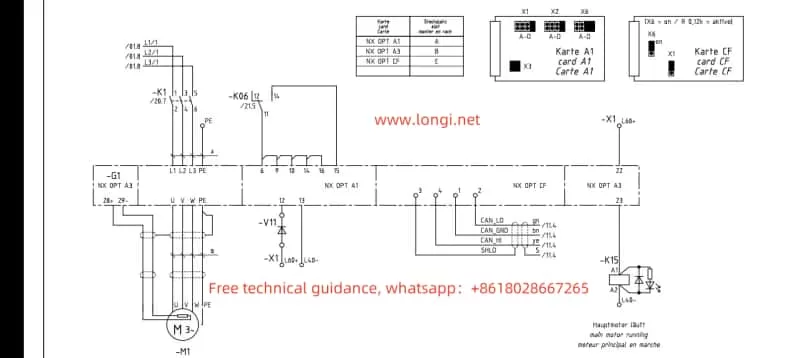
NXS-NXP actual wiring diagram

IV. How to Set Parameter Access Restrictions (Specific Parameters and Operations)

In addition to password protection, the Vacon NXS_NXP series inverters also provide a parameter access restriction feature, allowing users to restrict access and modification of specific parameters. Users can follow these steps to set parameter access restrictions:

  1. Enter the System Menu (M6).
  2. Find the Parameter Lock Option (usually labeled as S6.5.2).
  3. Enable Parameter Lock: Set the parameter lock option to “Locked” and confirm the execution. This will restrict access and modification of most parameters.
  4. Disable Parameter Lock: When needing to modify locked parameters, first set the parameter lock option to “Unlocked” and confirm the execution.

V. How to Achieve External Terminal Forward/Reverse Control and External Potentiometer Speed Regulation

The Vacon NXS_NXP series inverters support motor forward/reverse control through external terminals and speed regulation through external potentiometers. Users need to set the following parameters and connect corresponding terminals:

  1. Forward/Reverse Control:
    • Parameter Settings: No specific parameter settings are required, but ensure the control signal source is set to external terminal control (P3.1=1).
    • Wiring: Connect the external forward button or switch to DIN1 (or the designated forward input terminal), and connect the external reverse button or switch to DIN2 (or the designated reverse input terminal).
  2. External Potentiometer Speed Regulation:
    • Parameter Settings: Ensure AI1 (or the designated analog input terminal) is set to accept analog voltage or current signals (specific settings depend on the potentiometer type).
    • Wiring: Connect the output end of the potentiometer to AI1 (or the designated analog input terminal), and connect the common terminal of the potentiometer to AI1- (or the corresponding common terminal).

VI. Fault Codes and Their Solutions

The Vacon NXS_NXP series inverters feature comprehensive fault diagnosis capabilities. When a fault is detected, the inverter will display the corresponding fault code and fault information. The following are some common fault codes, their meanings, and solutions:

  1. Fault Code F01: Overcurrent
    • Meaning: Motor current exceeds the rated value.
    • Solution: Check if the motor load is too heavy, and check for short circuits or grounding in the motor and cables.
  2. Fault Code F02: Overvoltage
    • Meaning: DC bus voltage is too high.
    • Solution: Check if the power supply voltage is too high, extend the deceleration time, or increase the braking resistor.
  3. Fault Code F03: Ground Fault
    • Meaning: Motor or cable grounding.
    • Solution: Check the insulation resistance of the motor and cables.
  4. Fault Code F05: Charging Switch Fault
    • Meaning: Charging switch failure.
    • Solution: Check the charging switch and its connection lines, and replace the charging switch if necessary.

(Note: The above are only examples of some fault codes. For a complete list of fault codes and solutions, please refer to the inverter user manual.)

Through this guide, we hope to help users better understand and use the Vacon NXS_NXP series inverter user manual, achieving efficient and safe frequency control.

Posted on Leave a comment

Commitment of Longi Electromechanical Company to Protect Customers’ Privacy Rights

Our company attaches great importance to the protection of personal information of both existing and potential customers. The specific protection measures are as follows:

Advanced Encryption Technology: We employ advanced encryption technology to ensure the security of customer information during transmission and storage, preventing unauthorized third parties from obtaining it.

Strict Access Control: We limit the number of employees who can access customer information, and only authorized personnel are allowed to access relevant data, ensuring the confidentiality of the information.

Clear Privacy Policy: We have a clear privacy policy that details how we collect, use, and store customer information. We regularly update our privacy policy to ensure compliance with the latest legal and regulatory requirements. You can view our privacy policy by clicking [insert privacy policy link here].

Compliant Data Usage: We only use customer information when necessary to provide services and products, and we do not sell or share customer information with third parties unless explicitly agreed to by the customer.

Employee Security Training: We provide regular security training to our employees to ensure they understand and comply with data protection regulations, enhancing their awareness of information security.

Reasonable Data Retention: We only retain customer information for as long as permitted by law, and when customer information is no longer needed, we securely delete or anonymize it to prevent misuse.

Through these measures, we are committed to providing a safe and reliable environment for the protection of personal information. If you have any questions or need further assistance, please feel free to contact us.

Posted on Leave a comment

Operation Guide for Instar-Tech AE200H Series Frequency Converter User Manual

I. Introduction to Operation Panel Functions

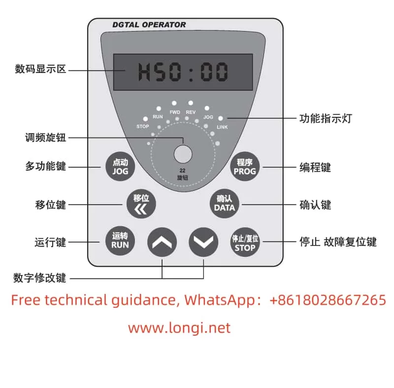
The Instar-Tech AE200H series frequency converter features a concise and straightforward operation panel design, facilitating intuitive operation and monitoring. The main function keys and indicator lights on the operation panel include:

  • RUN Key: Press this key to start the frequency converter. In programming mode, this key can be used as a shift key.
  • JOG Key: Press this key to enter jogging mode and switch between forward and reverse rotation.
  • STOP Key: Press this key to stop the frequency converter. After a fault alarm, pressing this key can reset the system.
  • PROG Key: Press this key to enter the function setting mode. After modification, press it again to exit the setting mode.
  • DATA Key: In programming mode, press this key to confirm the function code and parameter content. After modification, press it again to save the data.
  • UP Key and DOWN Key: In programming mode, use these keys to adjust the numerical values of function codes and parameter data.
  • Shift Key (<< / REV): In programming mode, use this key to shift during parameter data modification.

Additionally, the operation panel has multiple indicator lights to display the operating status of the frequency converter, such as the RUN, STOP, FWD, and REV indicators.

Function diagram of AE200H operation panel

II. Password Setting and Parameter Access Restrictions

To protect the frequency converter’s settings from unauthorized modification, the AE200H series provides a password setting function. Users can set a password to restrict access and modification of frequency converter parameters. The specific steps are as follows:

  1. Set Password: Enter programming mode, locate the user password parameter (e.g., P.089), and set a non-zero value as the password.
  2. Enter Password: When modifying parameters, the system will prompt for a password. Only by entering the correct password can you access the parameter modification interface.
  3. Eliminate Password: To eliminate the password, simply reset the user password parameter value to 0.

Furthermore, the AE200H series frequency converter offers parameter access restriction functions. Users can set different access levels to restrict different users’ access to frequency converter parameters.

III. Parameter Initialization

If users need to restore the frequency converter to its factory settings, they can perform a parameter initialization operation. The specific steps are as follows:

  1. Enter programming mode.
  2. Locate the factory reset parameter (e.g., P.XXX, refer to the user manual for specific codes) and set its value to 1.
  3. Press the DATA key to save the setting and restart the frequency converter.

After restarting, the frequency converter will return to its factory settings, and all user-set parameters will be cleared.

IV. Terminal Forward/Reverse Control and External Potentiometer Speed Regulation

The AE200H series frequency converter supports motor forward/reverse control through external terminals and speed regulation through an external potentiometer. The specific settings and wiring methods are as follows:

  1. Terminal Forward/Reverse Control
    • Parameter Setting: No special setting is required; ensure correct wiring.
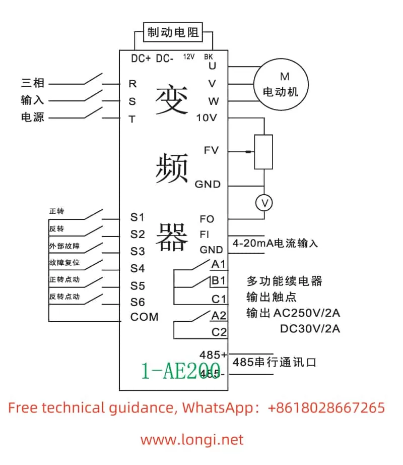
    • Wiring Method: Connect the forward control terminal (e.g., S1) and reverse control terminal (e.g., S2) to the corresponding contacts in the control circuit. By controlling the on/off status of these contacts, you can achieve motor forward/reverse rotation and stopping.
  2. External Potentiometer Speed Regulation
    • Parameter Setting: Locate the speed control mode selection parameter (e.g., P.XXX) and set its value to external given.
    • Wiring Method: Connect the output terminal of the external potentiometer to the speed regulation input terminal of the frequency converter (e.g., AI1 or AI2). By adjusting the resistance value of the potentiometer, you can change the output frequency of the frequency converter, thereby achieving motor speed regulation.

V. Fault Codes and Solutions

The AE200H series frequency converter features comprehensive fault diagnosis capabilities. When a fault occurs, the corresponding fault code will be displayed on the screen. Here are some common fault codes, their meanings, and solutions:

  1. OC1/OC2/OC3: Overcurrent during acceleration/deceleration/constant speed.
    • Meaning: The output current of the frequency converter exceeds the rated value.
    • Solution: Check if the motor load is excessive, check the power line connection for good contact, and check if the frequency converter parameter settings are reasonable (e.g., acceleration/deceleration time, overload protection).
  2. OU1/OU2/OU3: Overvoltage during acceleration/deceleration/constant speed.
    • Meaning: The input voltage of the frequency converter is too high or the braking resistor is damaged.
    • Solution: Check if the power supply voltage is stable and inspect the braking resistor for damage or poor connection.
  3. UV: Undervoltage on the bus.
    • Meaning: The input voltage of the frequency converter is lower than the rated voltage.
    • Solution: Check if the power supply voltage is normal and inspect the power line connection for good contact.
  4. OL1: Motor overload.
    • Meaning: The motor load is excessive or the motor parameter settings are incorrect.
    • Solution: Check if the motor load is excessive and verify the motor parameter settings (e.g., rated current, power).
  5. OH2: Frequency converter overheat.
    • Meaning: The internal temperature of the frequency converter is too high.
    • Solution: Check if the frequency converter installation environment is well-ventilated and inspect the cooling fan for normal operation.
AE200H standard wiring diagram

VI. Conclusion

This article provides a detailed operation guide for the Instar-Tech AE200H series frequency converter, covering the introduction to operation panel functions, password setting and parameter access restrictions, parameter initialization, terminal forward/reverse control, external potentiometer speed regulation, fault codes and solutions, and other related content. We hope this guide will help users better understand and utilize this series of frequency converters to ensure their efficient and stable operation.