Posted on Leave a comment

BEST Inverter FC300 User Manual Usage Guide and Distinction between HOC and OC Faults

I. Introduction to BEST Inverter FC300 Panel Functions and Parameter Settings

1.1 Introduction to Panel Functions

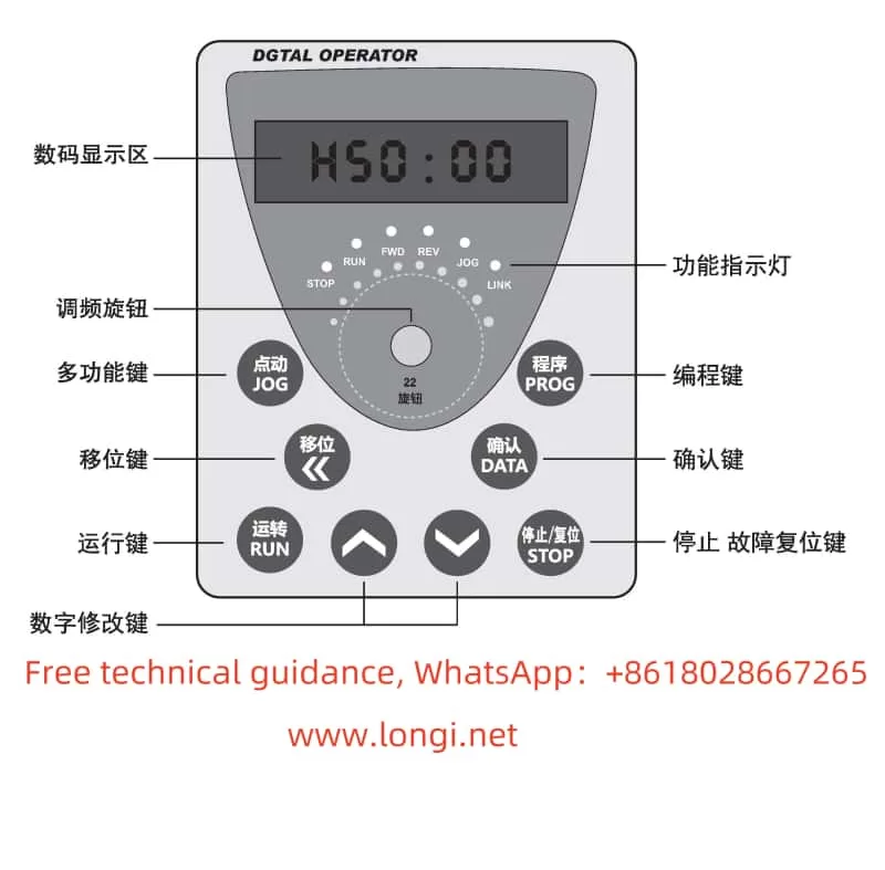
The BEST Inverter FC300’s operation panel is equipped with multiple function keys, including ESC, ENT, MF, >>, ↑, ↓, STOP/RESET, each with specific functions:

  • ESC: Exits the current setting or cancels the current operation.
  • ENT: Confirms the current setting or proceeds to the next operation.
  • MF: Multifunction key with different functions depending on the context.
  • >>: Switches between menus or parameters.
  •  and : Adjust parameter values or scroll through menus.
  • STOP/RESET: Stops the inverter operation or resets the fault status.
OC FAULT

1.2 Parameter Initialization and Upload/Download

The BEST Inverter FC300 supports parameter initialization, upload, and download, primarily through parameter P087.

  • Parameter Initialization: Set P087 to 1 and press ENT to confirm, restoring the inverter to factory settings.
  • Parameter Upload: Set P087 to 4, ensure correct connection between the inverter and computer, and upload current parameter settings via dedicated software.
  • Parameter Download: Set P087 to 5, ensure correct connection, and download parameters to the inverter via software.

1.3 Setting and Removing Passwords

To protect the inverter settings from unauthorized changes, the BAST FC300 supports password protection.

  • Setting a Password: Set a new password in P086 and choose 2 in P087 to memorize the password.
  • Removing a Password: Enter the current password in P086 and choose 3 in P087 to clear the password.

II. Terminal Start/Stop, Potentiometer Speed Adjustment, and Forward/Reverse Control

2.1 Terminal Start/Stop and Potentiometer Speed Adjustment

To achieve terminal-based start/stop of the inverter and potentiometer-based speed adjustment, correct wiring and parameter settings are required.

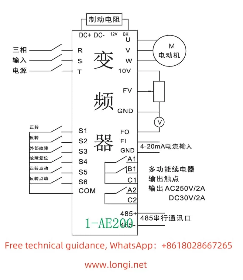
  • Wiring: Connect the start and stop signals to the X1 and X3 terminals of the inverter, respectively (or other designated terminals, as per the manual). Connect the potentiometer to the AVI or ACI terminals for analog speed adjustment.
  • Parameter Settings:
    • Set P064 to 1 to select external terminal control.
    • Configure the function of the AVI or ACI terminals, e.g., set P091’s X1 function to “Forward Start” and X3 to “Stop”.
    • Adjust parameters like P053 as needed to set the range and mode of analog speed adjustment.
HOC FAULT

2.2 Terminal-Based Forward/Reverse Control

To achieve terminal-based forward/reverse control of the inverter, correct wiring and parameter settings are also necessary.

  • Wiring: Connect the forward and reverse signals to the X1 and X2 terminals of the inverter, respectively (or other designated terminals).
  • Parameter Settings:
    • Ensure P064 is set to support external terminal control.
    • Configure the functions of the X1 and X2 terminals, e.g., set P091’s X1 function to “Forward” and X2 to “Reverse”.
    • Adjust parameters like P066 as needed to ensure motor reversal is allowed.

III. Distinction between HOC and OC Faults and Solutions

3.1 Distinction between HOC and OC Faults

  • HOC Fault: Typically refers to an overcurrent fault caused by damage to the inverter’s inverter module. This fault is severe and may be accompanied by damage to internal components of the inverter.
  • OC Fault: Generally refers to an overcurrent fault on the output side, which may be caused by motor stalls, excessive loads, short acceleration times, etc.

3.2 Fault Solutions

  • HOC Fault Solution:
    1. Check the Inverter Module: Confirm if the inverter module is damaged and replace it if necessary.
    2. Check the Drive Circuit: Inspect the drive circuit for normal function and troubleshoot drive faults.
    3. Contact the Manufacturer: If the issue is complex or unresolved, contact BAST for repair or replacement.
  • OC Fault Solution:
    1. Check the Motor and Load: Confirm if the motor is stalled or if the load is excessive, and adjust the load or motor parameters as necessary.
    2. Adjust Acceleration Time: Increase the acceleration time to avoid instantaneous overcurrent during motor startup.
    3. Check Wiring: Verify the wiring between the motor and the inverter for correctness and eliminate any wiring errors that may cause faults.
    4. Reset the Inverter: Press the STOP/RESET button to reset the inverter and attempt to restart it.

IV. Conclusion

The BEST Inverter FC300, as a high-performance inverter, boasts a rich set of panel functions and flexible parameter settings, capable of meeting control demands in various complex operating conditions. Through correct wiring and parameter settings, functions such as terminal-based start/stop, potentiometer speed adjustment, and forward/reverse control can be achieved. Meanwhile, for common HOC and OC faults, users should be able to quickly identify the fault phenomenon and take corresponding measures for resolution to ensure the normal operation of the inverter. During use, users must strictly adhere to the safety precautions and operating procedures outlined in the manual to ensure the safety of personnel and equipment.

Posted on Leave a comment

Guangzhou Numerical Control Servo Unit DA98A User Manual Usage Guide

I. Basic Operations and Parameter Settings of the Servo Unit

1. Factory Reset and Parameter Backup
  • Factory Reset: To restore the servo unit to its default parameter settings, first enter the special password for modifying motor parameters, PA0=385. Then, find the corresponding code for your motor model (refer to Appendix A) and input it into parameter PA1. Finally, execute the parameter restoration operation.
  • Parameter Backup: To prevent erroneous parameter modifications, you can back up the current parameters to the EEPROM backup area. Select the “Parameter Backup” option in the parameter management menu via the operation panel to complete the backup operation. To restore, select “Restore Backup”.
2. Setting the Motor Model Selection Parameter
  • Motor Model Selection: Choose the compatible motor model by setting parameter PA1. After inputting the correct motor model code, the servo unit will automatically load the corresponding default parameters.
3. Jog Start and Stop
  • Jog Operation: In the menu, select the jog operation mode (PA4=3), set the jog speed (PA21), and ensure PA98=1 to force internal enabling. Subsequently, control the motor’s start and stop for forward and reverse rotation using the “+” and “-” keys on the operation panel.
4. Parameter Optimization
  • Speed Loop and Current Loop Optimization: The adjustments to the speed loop proportional gain (PA5) and integral coefficient (PA6) affect the servo system’s response speed and stability. The adjustments to the current loop filter coefficient (PA7) and speed feedback filter coefficient (PA8) influence the current smoothness and speed feedback response speed. These parameters need to be fine-tuned based on specific motor models and load conditions to achieve optimal performance.
DA98A servo unit position mode wiring diagram

II. Wiring and Parameter Settings Under Position Mode Control

1. Wiring Instructions
  • Position Mode Wiring: The main connections include power input (R, S, T), motor output (U, V, W), control power (r, t), encoder feedback (CN2 interface), and control signals (CN1 interface). Refer to the wiring diagrams in the manual for specific terminal connections.
2. Forward and Reverse Control
  • Forward and Reverse Implementation: Realize motor forward and reverse control by inputting pulse and direction signals through the PULS+, PULS-, and SIGN+, SIGN- terminals of the control signal CN1, or by using CCW and CW pulses. Set parameter PA14 to choose the pulse input mode (pulse + direction or CCW/CW pulses).
3. Key Parameter Settings
  • Position Command Electronic Gear Ratio: Adjust the electronic gear ratio to match different pulse sources and control resolutions by setting parameters PA12 (pulse command multiplication coefficient) and PA13 (pulse command division coefficient).
  • Position Command Pulse Input Mode: Set parameter PA14 to 0 for pulse + direction mode or to 1 for CCW/CW pulse mode.
  • Position Arrival Signal: Set the position arrival range pulse number by adjusting parameter PA16. When the remaining pulse number in the position deviation counter is less than or equal to this value, the COIN signal outputs ON.
DA98A servo unit main circuit wiring diagram

III. Fault Codes and Solutions

1. List of Fault Codes and Their Meanings
  • Err-1: Overspeed, indicating that the servo motor speed exceeds the set value.
  • Err-2: Overvoltage in the main circuit, indicating that the main circuit power supply voltage is too high.
  • Err-3: Undervoltage in the main circuit, indicating that the main circuit power supply voltage is too low.
  • Err-4: Position error, indicating that the value in the position deviation counter exceeds the set value.
  • Err-9: Encoder fault, indicating that the encoder signal is erroneous.
  • Err-11: IPM module fault, indicating that the IPM intelligent module is faulty.
  • Err-12: Overcurrent, indicating that the motor current is too high.
  • Err-13: Overload, indicating that the servo unit and motor are overloaded.
2. Solutions
  • Err-1: Check the control circuit board, motor encoder, input pulse frequency, and electronic gear ratio settings, or adjust the load moment of inertia ratio.
  • Err-2: Check the power supply, braking resistor wiring, internal braking resistor or circuit, or reduce the start-stop frequency and load inertia.
  • Err-3: Confirm the main circuit power wiring, power supply voltage, power capacity, and heat sink status.
  • Err-4: Check the pulse command frequency, electronic gear ratio settings, load inertia, motor encoder and its connections, or adjust the speed loop and position loop gains.
  • Err-9: Inspect the encoder connector and signal wire soldering, shorten the encoder cable length, or replace the motor encoder.
  • Err-11: Replace the servo unit, check the braking resistor wiring, adjust the current loop parameters, or reduce the load inertia.
  • Err-12: Reduce the load, check the grounding, or replace the motor.
  • Err-13: Adjust the speed loop gain, increase the acceleration/deceleration time, reduce the load inertia, or replace the high-power servo unit and motor.

IV. Scientific Usage Process of the Servo System

  1. System Installation and Wiring: Install the servo unit and motor correctly according to the installation instructions and wiring diagrams in the manual, ensuring all connections are accurate and error-free.
  2. Parameter Setting and Debugging: Set the corresponding parameters based on the motor model in use and conduct necessary debugging, including the optimization of key parameters such as the speed loop and current loop.
  3. Functional Testing: Conduct manual, jog, speed mode, and position mode operation tests under no-load conditions to ensure the servo system functions normally.
  4. Load Operation: After confirming the normal operation of the servo system under no-load conditions, connect the load for loaded operation testing and monitor the motor’s operating status and performance indicators.
  5. Fault Handling and Maintenance: In case of alarms or faults during use, troubleshoot and resolve them according to the fault codes and handling methods in the manual. Meanwhile, regularly maintain and service the servo unit and motor to ensure their long-term stable operation.
By following the above steps, you can ensure the scientific use and maintenance of the Guangzhou Numerical Control (GSK CNC) Servo Unit DA98A, improving production efficiency and equipment reliability.

Posted on Leave a comment

Guide to the LCGK-ZTV Inverter LC630 Series from Lianchuang High-Tech & Zhongtaiwei and Troubleshooting for Err23

I. Introduction to Panel Functions and Initialization Settings of the LCGK-ZTV Inverter LC630 Series

1. Panel Function Introduction

The LC630 series inverters from LCGK-ZTV are equipped with an intuitive operation panel, which mainly includes a display screen, function keys, and status indicator lights. The display screen shows current working status, parameter settings, and other information; the function keys include “MENU” (menu), “ENTER” (confirm), “UP/DOWN” (selection), etc., used for parameter setting and navigation; the status indicator lights indicate power, operation, faults, and other statuses.

LC630 inverter

2. Initialization and Password Setting

Initializing the inverter typically involves restoring default parameter settings. The specific steps are as follows:

  • Press the “MENU” key to enter the main menu.
  • Use the “UP/DOWN” keys to select the “Initialization” option and press “ENTER” to confirm.
  • The system will prompt whether to confirm initialization; press “ENTER” again to execute.

The LCGK-ZTV Inverter LC630 series supports password protection to prevent unauthorized modifications. The method for setting a password is as follows:

  • After entering the main menu, select the “Parameter Protection” option.
  • Use the “UP/DOWN” keys to select “Password Setting,” and press “ENTER” to enter.
  • Input the desired password (typically a 4-digit number) and press “ENTER” to confirm.
  • Input the password again for confirmation and press “ENTER” to save.

The method for clearing the password is similar. Simply select “Clear Password” after entering the current password in the “Password Setting” option and press “ENTER” to confirm.

3. Setting Panel Start and Panel Potentiometer Speed Adjustment

To achieve panel start and panel potentiometer speed adjustment, the following parameters need to be set:

  • Pr033: Start source selection. Set to 0 for panel start; set to other values for external signal start.
  • Pr034: Operating frequency source selection. Set to 0 for panel potentiometer speed adjustment; set to other values for external signal speed adjustment.
  • Pr052: Enable PID function (set according to specific situations when used for constant pressure water supply control).

II. Method for Achieving Constant Pressure Water Supply Control

1. Introduction to PID Function

The PID control is key to achieving constant pressure water supply control with the inverter. By monitoring changes in water supply pressure, the PID controller automatically adjusts the output frequency of the inverter to maintain a constant water supply pressure.

2. Parameter Setting

According to the instruction manual for the LCGK-ZTV Inverter LC630 series (especially pages 58, 59, and 60), the following parameters need to be set to achieve constant pressure water supply control:

  • Pr052: Enable PID function. Set to a non-zero value to enable PID control.
  • Pr100: PID target value setting. Set the target value according to the required water supply pressure.
  • Pr101: PID feedback signal source selection. Typically, select the output signal from the pressure sensor as the feedback signal.
  • Pr102Pr103Pr104: Set the P (proportional), I (integral), and D (derivative) parameters of PID control, respectively. These parameters need to be adjusted according to the actual system response to achieve the best control effect.
  • Pr105: PID output limiting. Set the maximum and minimum values of the PID output signal to prevent the inverter output frequency from exceeding the allowed range.

3. Notes

  • When setting PID parameters, ensure system stability and quick response.
  • Regularly check the accuracy of the pressure sensor and feedback signal to ensure the accuracy of PID control.
  • Adjust PID parameters according to actual water supply demands and pump performance to achieve optimal energy-saving effects.
err23 fault

III. Troubleshooting for Err23

1. Fault Mechanism Analysis

The Err23 fault code typically indicates a short circuit between the inverter output and ground. This may be caused by insulation failure of the motor or motor cables. When a short circuit occurs between the inverter output and ground, an excessively large current is generated, triggering the protection mechanism and displaying the Err23 fault code.

2. Fault Handling Method

When handling the Err23 fault, first check the insulation of the cables and motor:

  • Disconnect the inverter’s power supply to ensure safe operation.
  • Use an insulation resistance tester to test the insulation of the cables and motor. Check the insulation resistance between each phase of the cable and ground, as well as the insulation resistance of the motor windings, to ensure they meet the requirements. If the insulation resistance value is too low, it indicates insulation failure.
  • For cables, replace them with new ones that match the specifications of the original cables. During replacement, ensure the integrity and insulation performance of the cables to avoid new damage during wiring.
  • For the motor, if the insulation failure is severe, the entire motor may need to be replaced. When replacing the motor, ensure that the specifications and performance of the new motor match those of the original motor to meet the operational requirements of the inverter.
  • If the Err23 fault code persists after replacing the cables or motor, it may be necessary to consider replacing the entire unit. This typically indicates that there may be other faults within the inverter causing the ground short circuit issue.
Posted on Leave a comment

Innov-X Alpha Series Spectrometer User Guide

I. Introduction to XRF Technology and Innov-X Alpha Series Performance Characteristics

1.1 Introduction to XRF Technology

X-Ray Fluorescence Spectrometry (XRF) is a powerful tool for elemental analysis and quantification. It works on the principle that different elements, when excited by X-rays, emit fluorescent X-rays with specific energies or wavelengths. These characteristics of the emitted X-rays can be used to identify and quantify the elements present in a sample.

α-6500

1.2 Innov-X Alpha Series Performance Characteristics

The Innov-X Alpha series of spectrometers are portable XRF analyzers featuring the following notable characteristics:

  • Portability: Designed for handheld use, facilitating on-site analysis.
  • Battery-Powered: Equipped with rechargeable lithium-ion batteries for extended operation.
  • High Precision: Utilizes a high-resolution silicon PIN diode detector for accurate elemental analysis.
  • Versatility: Suitable for analyzing alloys, soils, paints, and various other sample types.
  • User-Friendly: Integrated with an HP iPAQ Pocket PC for an intuitive operation interface.
  • Automatic Compensation: Automatically compensates for irregular or small samples, enhancing analysis accuracy.

II. Basic Operational Workflow and Radiation Safety Precautions

2.1 Basic Operational Workflow

  1. Inspection and Preparation: Ensure all accessories are present, batteries are fully charged, and the iPAQ is also charged.
  2. Power-On: Press the power switch on the back of the analyzer, followed by the power button on the iPAQ.
  3. Software Initiation: Select the Innov-X software on the iPAQ to begin using the analyzer.

2.2 Radiation Safety Precautions

  • Pre-Operational Preparation: Ensure operators have undergone radiation safety training and obtained the corresponding certificate.
  • Operational Norms: Never point the analyzer at any part of the body, especially during testing.
  • Radiation Warnings: Pay attention to the red indicator light on the analyzer and the warning label on the back, ensuring no one is around during testing.
  • Regular Monitoring: Use personal dosimeters to regularly monitor radiation exposure.
standardization failed

III. Routine Operational Procedures

3.1 Standardization Procedure

  • Steps: Perform standardization before each use or after hardware reset. Place the standardization cap over the analyzer probe and press the standardization button on the screen, waiting for completion.
  • Precautions: If standardization fails, check the placement of the cap, battery level, and restart the analyzer if necessary.

3.2 Software Trigger Lock

  • Function: Prevents accidental triggering, ensuring safe operation.
  • Operation: Unlock the trigger by tapping the lock icon on the iPAQ screen before testing. The trigger will automatically lock if no test is performed within five minutes.

3.3 Testing and Outputting Results

  • Testing: Align the probe with the sample and press the trigger or the start button on the iPAQ to initiate testing.
  • Viewing Results: Upon completion, results will automatically display on the iPAQ screen. Detailed data and spectra can be viewed on the results screen.
  • Data Export: Use ActiveSync software to connect the iPAQ to a computer and export test results to Excel or other software for further analysis.
count rate too low

IV. Operating Guide for Soil Mode

4.1 Soil Mode Setup

  • Mode Selection: Choose the “Soil” mode from the main menu.
  • Test Time Settings: Configure the minimum and maximum test times, as well as the test end conditions (e.g., maximum time, relative standard deviation).

4.2 Testing Steps

  • Sample Preparation: Place the soil sample in a test cup or on the test stand, ensuring it fully covers the probe window.
  • Initiate Testing: Press the trigger or the start button on the iPAQ to begin testing.
  • Result Analysis: After testing, review the element concentrations and spectra on the results screen, and export data as needed.

V. Fault Analysis and Troubleshooting

5.1 Inability to Standardize (Low Count Rate)

  • Possible Causes: Insufficient battery power, improper placement of the standardization cap, detector contamination or damage.
  • Troubleshooting:
    1. Check the battery level and ensure it is fully charged.
    2. Reposition the standardization cap to ensure it fully covers the probe window.
    3. Clean the detector window to remove any dirt or obstructions.
    4. If the issue persists, contact Innov-X technical support for further inspection and repair.

VI. Conclusion

The Innov-X Alpha series of spectrometers, with their portability, high precision, and versatility, offer wide applications in the field of elemental analysis. By following the operational procedures and radiation safety precautions outlined in this user guide, operators can safely and effectively conduct analyses on various samples. Additionally, understanding common faults and troubleshooting methods will help ensure the stable operation of the analyzer and extend its service life.

Posted on Leave a comment

Fault Analysis and Handling for Inverter Displaying “88888” upon Power-up, with All Indicators Lit and No Response to Any Button Press

In inverter maintenance, it is common to encounter a situation where upon power-up, the inverter displays “88888”, all indicators are lit, and pressing any button results in no response. This fault typically indicates the following possibilities:

INDVS inverter shows 88888
  1. Power Issues: For example, voltage fluctuations or instability may prevent the inverter from completing its initialization process.
  2. Hardware Faults: Components such as the control board, drive board, or power supply may be damaged or malfunctioning.
  3. Communication Problems: Interruptions or errors in communication between the inverter and other devices may cause abnormal displays.
  4. Software or Firmware Issues: There may be bugs or incompatibilities in the inverter’s software or firmware that need to be addressed.

To troubleshoot this issue, the following steps can be taken:

Inovance inverter shows 88888
  1. Check Power Supply: Ensure that the voltage is stable and within the operating range specified by the inverter.
  2. Inspect Hardware: Open the inverter’s casing and inspect the control board, drive board, and power supply for any signs of damage or malfunction. Replace any faulty components as necessary.
  3. Test Communication: Verify that the communication lines between the inverter and other devices are properly connected and free from interference.
  4. Update Software/Firmware: If suspected, try updating the inverter’s software or firmware to the latest version.
  5. Reset the Inverter: Perform a hard reset of the inverter to see if it can recover from a stuck initialization state.

If the above steps fail to resolve the issue, it is recommended to contact the manufacturer’s technical support or a professional repair service for further assistance. Regular maintenance and inspections can also help prevent such faults from occurring in the first place.

Posted on Leave a comment

Shenzhen SHZHD Inverter V680 Series Operation Guide and E10 Fault Handling

Shenzhen SHZHD Inverter V680 Series Operation Guide and E10 Fault Handling

I. Operation Panel Function Introduction, Parameter Factory Reset, and Password Management

SHZHD INVERTER V680

1. Operation Panel Function Introduction

The operation panel of the Shenzhen SHZHD Inverter V680 series provides an intuitive operation interface, allowing users to set various parameters and operate the inverter through buttons and displays on the panel. The main functions of the panel include:

  • Display Area: Displays current set frequency, output frequency, current, voltage, and other parameters.
  • Function Keys: Such as MENU, ENTER, △, ▽, used for entering menus, confirming settings, and adjusting parameters.
  • Run Key: Starts and stops the inverter.
  • Fault Indicator: When the inverter malfunctions, the corresponding indicator light will illuminate, prompting the user to check the fault.

2. Parameter Factory Reset

To restore the inverter’s parameters to their factory defaults, follow these steps:

  1. Enter the menu interface and find the “Parameter Initialization” option.
  2. Select “Restore Factory Parameters” and confirm execution. At this point, all parameters except motor parameters will be restored to their factory settings.

3. Adding and Removing Passwords

To protect parameters from being modified casually, users can set passwords for the inverter.

  • Adding a Password: Enter the “User Password” setting, input the desired password, and confirm to save.
  • Removing a Password: Re-enter the “User Password” setting and set the password to 0 to remove password protection.

II. Torque Control and Vector Control

1. Torque Control

Torque control is a special control mode that allows users to directly set the output torque of the inverter instead of indirectly controlling the torque by setting the frequency. This control mode is very useful in situations where precise control of the load torque is required.

  • Setting Method: First, select “Torque Control” in the control mode. Then, choose the torque setting source through the corresponding parameter (such as A0-01), which can be the keyboard, analog input, communication, etc. Finally, set the desired torque value through parameters such as A0-03.

2. Vector Control

Vector control is a high-performance control method that achieves high-precision speed and torque control by precisely controlling the motor’s current and magnetic flux.

  • Optimizing Parameters: To obtain better vector control performance, users need to adjust related parameters based on the actual load conditions, such as the speed loop proportional gain (P2-00, P2-03) and speed loop integral time (P2-01, P2-04). The adjustment of these parameters requires certain professional knowledge and experience.

III. Terminal Start/Stop and Potentiometer Speed Regulation

1. Terminal Start/Stop

Controlling the start and stop of the inverter through external terminals is a commonly used control method. Users need to set the control mode of the inverter to “Terminal Control” and wire it correctly.

  • Wiring Terminals: Typically include the forward start terminal (e.g., DI1), reverse start terminal (e.g., DI2), and stop terminal (e.g., DI3).
  • Parameter Settings: Select “Terminal Command Channel” in P0-02 and set the corresponding terminal functions.

2. Potentiometer Speed Regulation

Potentiometer speed regulation is a simple speed regulation method where users can change the set frequency of the inverter by rotating the potentiometer, thereby achieving speed regulation.

  • Wiring Terminals: Connect the output end of the potentiometer to the analog input terminal of the inverter (e.g., AI1).
  • Parameter Settings: Select “Analog AI1 Setting” as the frequency source in P0-03.
E10 FAULT

IV. E10 Fault Handling

1. On-site Handling

The E10 fault typically indicates an overload of the inverter. When an overload fault occurs, users should first check if the load is too heavy or if the motor is stalled. If the load is normal, try increasing the inverter’s acceleration and deceleration times to reduce the impact on the motor.

2. Maintenance Handling

If on-site handling fails to resolve the issue, it may be necessary to disassemble the inverter for maintenance. During the maintenance process, focus on the following aspects:

  • Motor and Load: Confirm whether the motor and load are normal and free from mechanical faults or obstructions.
  • Inverter Parameters: Check whether the inverter’s overload protection parameters (such as P9-00, P9-01) are set reasonably.
  • Hardware Faults: If the parameter settings are normal and the load is without abnormality, it may be a hardware fault within the inverter, such as damaged power devices or poor heat dissipation. At this point, professional maintenance personnel should be sought for assistance.

Conclusion

The Shenzhen SHZHD Inverter V680 series is a powerful and flexible inverter product. Through this guide, users can better understand the inverter’s operation panel functions, parameter setting methods, the application of torque control and vector control, and common fault handling methods. In practical applications, users should configure parameters and control modes based on specific needs and load conditions to ensure stable operation and high performance of the inverter.

Posted on Leave a comment

Kingda Inverter V380 Series User Manual Operation Guide

Kingda Inverter V380 Series User Manual Operation Guide

I. Introduction to Inverter Operation Panel Functions and Factory Reset

The Kingda Inverter V380 series features a versatile operation panel with the following main keys:

  • Run/Stop Key: Used to start or stop the inverter.
  • Forward/Reverse Key: Used to control the motor’s forward and reverse rotation, respectively.
  • Stop/Fault Reset Key: Used to reset or stop the inverter in case of a fault.
  • Return Key: Used to switch between monitoring modes or return to the previous state.
  • Confirm Key: Confirms the current status or parameter and enters the next level of the function menu.
  • Data Modify Key: Used to modify function codes or parameters.
  • Shift Key: Used to move the cursor position when setting parameters.
Kingda Inverter V380 Operation Panel

Factory Reset:

  • To restore factory settings, enter the parameter settings interface, find the P0.03 parameter (Parameter Initialization), set it to 1, and then press the confirm key to execute the initialization. This operation will clear all user-defined parameters, and the inverter will revert to its factory default settings.

Carrier Frequency and Carrier Characteristic Parameters:

  • Carrier Frequency: Refers to the frequency of the PWM (Pulse Width Modulation) signal within the inverter, affecting the harmonic content of the output current and motor noise levels. A higher carrier frequency reduces harmonic content but increases switching losses, potentially leading to increased inverter heat generation.
  • Carrier Characteristic Parameter (P0.12): Controls whether the carrier frequency changes with the output frequency. When set to 0, the carrier frequency does not change with the output frequency; when set to 1, the carrier frequency increases with the output frequency, helping to reduce noise and vibration at lower frequencies.
  • Setting Carrier Frequency: Enter the parameter settings interface, find the P0.11 parameter (Carrier Frequency), and adjust its value according to actual needs, typically ranging from 0.8 to 15.0 KHz.

II. Terminal Start/Stop and External Potentiometer Speed Regulation Settings

Terminal Start/Stop:

  • Wiring: Connect external control signals to the inverter’s DI (Digital Input) terminals. Typically, the forward start signal is connected to DI1, the reverse start signal to DI2, and the stop signal to DI3 (or a combination of states shared by DI1 and DI2).
  • Parameter Settings: Enter the parameter settings interface and set P1.05 (Run Command Channel) to 1 (Terminal Control Start/Stop).
Kingda Inverter V380

External Potentiometer Speed Regulation:

  • Wiring: Connect the output of the external potentiometer to the inverter’s AI1 (Analog Input 1) terminal. The sliding end of the potentiometer is used to adjust the output voltage, thereby controlling the inverter’s output frequency.
  • Parameter Settings: Enter the parameter settings interface, set P1.00 (Main Frequency Channel A Selection) to 3 (Panel Potentiometer), and set P2.00 and P2.01 to the lower and upper voltage limits of AI1 input, respectively.

III. Modbus Protocol Settings and PID Control via Siemens PLC (S7-200)

To achieve PID control (e.g., single-pump constant pressure water supply) of the inverter via a Siemens PLC (S7-200) using the Modbus protocol, the following settings are required:

  • Modbus Parameter Settings:
    • Enter the parameter settings interface, set the units place of P9.00 (Communication Settings) to the corresponding baud rate (e.g., 4 for 9600 bps), and the tens place to the data format (e.g., 0 for no parity).
    • Set P9.01 (Device Address) to the Modbus address of the inverter.
    • Ensure P9.04 (Communication Timeout Fault Detection Time) is set reasonably to avoid communication interruptions.
  • PID Control Parameter Settings:
    • Enter the parameter settings interface and enable the built-in PID control (P8.00 set to a non-zero value).
    • Set the PID setpoint and feedback channels (P8.01), typically selecting the external voltage signal AI1 as the feedback channel.
    • Adjust PID proportional constant (P8.07), integral constant (P8.08), and other parameters according to control requirements.
  • PLC Programming:
    • Write a Modbus communication program in the Siemens PLC (S7-200) to read the current status of the inverter and send PID setpoints.
    • Write a PID control algorithm program to adjust the setpoint based on the feedback signal, achieving control objectives such as constant pressure water supply.

IV. Fault Code Analysis and Solutions

The Kingda Inverter V380 series features comprehensive fault protection. When a fault occurs, the inverter displays the corresponding fault code. Below are some common fault codes, their analysis, and solutions:

  • EC.01: Overcurrent during acceleration. Possible causes include too short an acceleration time, an inappropriate V/F curve, etc. Solutions include extending the acceleration time, adjusting the V/F curve, etc.
  • EC.02: Overcurrent during deceleration of the inverter. A possible cause is too short a deceleration time. The solution is to increase the deceleration time.
  • EC.03: Overcurrent during inverter operation or stoppage. Possible causes include sudden load changes, low grid voltage, etc. Solutions include reducing load fluctuations and checking the power supply voltage.
  • EC.04 to EC.07: Related to overvoltage faults, possible causes include abnormal power supply voltage, improper deceleration time settings, etc. Solutions include checking the power supply voltage and adjusting the deceleration time.
  • EC.12 and EC.13: Indicate inverter and motor overload, respectively. Possible causes include excessive load, too short an acceleration time, etc. Solutions include reducing the load and extending the acceleration time.

For other fault codes, refer to the Fault Diagnosis and Countermeasures section of the user manual for detailed analysis and solutions. When troubleshooting, ensure that the inverter is powered off and take necessary safety measures.

V. Conclusion

This document provides a detailed introduction to the operation guide of the Kingda Inverter V380 series, including the operation panel function introduction, factory reset method, carrier frequency and carrier characteristic parameter settings, terminal start/stop and external potentiometer speed regulation settings, Modbus protocol and PLC PID control settings, as well as fault code analysis and solutions. With this guide, users can better understand and utilize this inverter to achieve efficient and stable motor control.

Posted on Leave a comment

User Manual and Operating Guide for Hitachi Inverter SJ300


I. Basic Operation and Monitoring Functions

  1. Panel Setting and Monitoring
    Setting to Display Current, Bus Voltage, and Frequency

Display Current: First, enter the monitoring mode via the panel buttons (typically by selecting the monitoring mode with the “FUNC” key). In monitoring mode, use the up and down arrow keys to browse through different monitoring parameters, find the current monitoring item, and confirm.
Display Bus Voltage: Similarly, in monitoring mode, use the up and down arrow keys to find the bus voltage monitoring item and confirm.
Display Frequency: Frequency is one of the most commonly used monitoring parameters and is usually directly displayed on the main interface of the monitoring mode. If not displayed, select the frequency monitoring item with the arrow keys.
Monitoring Terminal Status

Enter monitoring mode, then select “Smart Input Terminal Status” or “Smart Output Terminal Status” for monitoring. These statuses include the switching state of the terminals, signal voltage, etc.
Panel Start/Stop and Speed Adjustment

Functional diagram of the operation panel for Hitachi inverter SJ300.

Start and Stop: In standard setting mode, start the inverter with the “RUN” key and stop it with the “STOP/RESET” key.
Speed Adjustment: Speed adjustment is typically achieved by changing the frequency setting value. On the panel, use the up and down arrow keys to adjust the frequency setting value, then press the “Store” key to confirm.
II. Multi-Speed Function Setting

  1. Setting Multi-Speed
    Assuming four speeds are needed, namely 10Hz, 20Hz, 40Hz, and 50Hz, the specific steps are as follows:

Wiring:
Connect external control signals (such as switch signals) to the inverter’s multi-speed control terminals (such as FW, 8, 7, 6, etc.).
Ensure correct connection of the control signal power supply and grounding.
Parameter Setting:
Enter standard setting mode and find parameters related to multi-speed control (such as A038, A039, etc.).
Set A038=00 (indicating external terminal control for multi-speed).
Set A039=04 (indicating 4-speed control).
Set the corresponding frequency values for the four speeds in the “F001” parameter: F001=10Hz (first speed), A020=20Hz (second speed), A220=40Hz (third speed), A320=50Hz (fourth speed).
III. Communication Protocol Setting

Standard wiring diagram for Hitachi inverter SJ300.
  1. Communication with Mitsubishi FX2N Series PLC
    Communication Method: Assuming RS485 communication is used.
    Parameter Setting:
    In the inverter, set C070=03 (select RS485 communication).
    Set C071 to the desired baud rate (e.g., C071=04 for 4800bps).
    Set C072=1 (8 data bits).
    Set C073=7 (no parity check).
    Set C074=0 (1 stop bit).
    On the PLC side, configure the corresponding RS485 communication parameters to match the inverter.
    IV. Simple Analysis and Handling of Fault Codes
  2. Common Fault Codes
    E02: Overcurrent Alarm. Possible causes include excessive motor load, motor stall, etc. Troubleshooting includes checking motor load, checking for motor stall, etc.
    E03: Overload Alarm. Possible causes include the motor operating overloaded for a long time. Troubleshooting includes reducing the load, increasing motor capacity, etc.
    E05: Overvoltage Alarm. Possible causes include excessively high input voltage. Troubleshooting includes checking if the input voltage is normal, adding input voltage protection, etc.
  3. Handling Steps
    Check the Alarm Code: When the inverter alarms, first check the alarm code displayed on the panel.
    Analyze Possible Causes: Based on the alarm code and site conditions, analyze possible fault causes.
    Take Measures: Based on the analysis results, take corresponding troubleshooting measures.
    Reset the Inverter: After troubleshooting, press the “STOP/RESET” key to reset the inverter and restart it.
    V. Summary

The Hitachi Inverter SJ300 series user manual provides detailed operating instructions and parameter setting methods. By carefully reading the manual and following the guidelines, users can easily monitor, control, and troubleshoot the inverter. Particular attention should be paid to correct parameter configuration and wiring accuracy when setting the multi-speed function and communicating with PLCs. Proper use of the inverter can significantly improve the operational efficiency and stability of the motor system.

Posted on Leave a comment

Operation Guide for Hitachi Inverter SJH300 Series User Manual

I. Introduction to Operation Panel Functions, Factory Default Reset, and Password Management

The Hitachi Inverter SJH300 series features an intuitive operation panel that integrates various functions for easy configuration and monitoring. The operation panel includes:

Functional Diagram of the Operation Panel for Hitachi Inverter SJH300
  1. Operation Panel Function Introduction:
    • Digital Operator (OPE-S): The standard-equipped digital operator provides a user-friendly interface for setting parameters, monitoring operating conditions, and controlling the inverter. Key functions include setting output frequency, selecting operation direction, and initiating start/stop commands.
    • Monitor Modes: The panel displays various monitor modes, such as output frequency, output current, operation direction, and alarm status, to provide real-time feedback on the inverter’s performance.
  2. Resetting to Factory Defaults:
    • To restore the inverter to its factory default settings, you need to navigate to the appropriate parameter (typically b084) in the function mode and set it to 01 for data initialization or 02 for both trip history clear and data initialization. This action resets all parameters to their default values, effectively restoring the inverter to its out-of-the-box state.
  3. Password Management:
    • Setting a Password: To set a password for parameter access, use the C070 parameter to select the data command mode (e.g., 03 for RS485 communication). Then, configure the relevant communication parameters (such as transmission speed, code, bit, and parity) to establish a secure communication channel.
    • Eliminating a Password: To remove the password, simply reset the C070 parameter to its default value (02 for operator mode), which disables password protection and allows unrestricted access to all parameters.
Standard wiring diagram for Hitachi Inverter SJH300 series.

II. Terminal Start/Stop, Forward/Reverse Control, and External Potentiometer Speed Adjustment

The Hitachi Inverter SJH300 series offers flexible control options, including terminal start/stop, forward/reverse control, and external potentiometer speed adjustment. Here’s how to configure these features:

  1. Terminal Start/Stop and Forward/Reverse Control:
    • Wiring: Connect the start (FW) and stop (RV) terminals to the appropriate control signals. For forward/reverse control, you may need to assign specific intelligent input terminals (e.g., terminals 7, 8 for forward/reverse commands).
    • Parameter Setting:
      • Set A002 to 01 to select terminal operation command.
      • Configure F004 to select the desired operation direction (00 for forward, 01 for reverse).
      • If using intelligent input terminals for forward/reverse control, assign the corresponding terminals (e.g., terminals 7, 8) and set the appropriate function codes (C001-C008).
  2. External Potentiometer Speed Adjustment:
    • Wiring: Connect the external potentiometer (typically a 10kΩ linear potentiometer) across the O-L (0-10V) terminals. Ensure proper grounding and shielding to avoid noise interference.
    • Parameter Setting:
      • Set A001 to 01 to select terminal frequency command.
      • Configure A011 (O start) and A012 (O end) to define the minimum and maximum output frequencies corresponding to the potentiometer’s minimum and maximum resistance values.
      • Adjust A013 (O start rate) and A014 (O end rate) if linear adjustment is not achieved directly with the potentiometer.

By following these steps, you can effectively configure the Hitachi Inverter SJH300 series for terminal-based start/stop and forward/reverse control, as well as external potentiometer speed adjustment, to suit your specific application requirements.

Posted on Leave a comment

Analysis, Types, and Maintenance Solutions for Delta Inverter GFF Fault

I. Meaning and Internal Mechanism of Delta Inverter GFF Fault

When a Delta inverter reports a “GFF” fault code, it indicates a “Ground Fault” (GFF) has occurred at the output terminal. This fault typically involves issues with the output circuit, such as damage to the IGBT, a short circuit in the output, or problems with the driver circuit, particularly when using PC929 optocouplers.

Physical picture of Delta INVERTER MS300 series

II. Analysis of the GFF Fault Scenario Described

In the scenario provided, the Delta inverter reports a GFF fault immediately upon connecting the motor, but the fault disappears when the motor wires are disconnected and the inverter is started alone. This suggests that the issue lies with the motor or the connection between the motor and the inverter, rather than the inverter itself.

Possible Causes:

  1. Motor Wiring Issues:
    • Short circuit or ground fault in the motor wiring.
    • Poor connection or loose wires at the motor terminals.
  2. Motor Problems:
    • Internal short circuit or ground fault within the motor.
    • Insulation failure or damage in the motor windings.
  3. External Interference:
    • Electromagnetic interference from nearby equipment affecting the inverter’s output circuit.
  4. IGBT or Driver Circuit Damage:
    • Although less likely in this case (since the fault disappears without the motor), damage to the IGBT or driver circuit could still be a factor if there are underlying issues with the inverter’s output stage.
b4GFF fault

III. Steps for Troubleshooting and Maintenance

  1. Check Motor Wiring:
    • Ensure all motor wires are properly connected and tightened.
    • Inspect the wires for any signs of damage, wear, or short circuits.
  2. Insulation Resistance Test:
    • Perform an insulation resistance test on the motor to check for insulation failure.
  3. Disconnect and Reconnect Motor:
    • Disconnect and then reconnect the motor wires to ensure a good connection.
    • Use a multimeter to test for continuity and shorts between the motor wires and ground.
  4. Isolate the Motor:
    • Try running the inverter with a different motor (if available) to determine if the fault lies with the motor or the inverter.
  5. Check Inverter Output Circuit:
    • Inspect the inverter’s output circuit for any signs of damage, particularly around the IGBTs and driver circuitry.
    • Replace any damaged components if necessary.
  6. Consult the Manual and Technical Support:
    • Refer to the Delta Inverter manual for more detailed troubleshooting steps and fault codes.
    • Contact Delta technical support for assistance if the issue cannot be resolved.

IV. Conclusion

The GFF fault reported by the Delta inverter is likely related to the motor or its connection to the inverter. By systematically checking the motor wiring, performing insulation resistance tests, and isolating the motor, the root cause of the fault can be identified and resolved. If the fault persists, further inspection of the inverter’s output circuit may be necessary.