
I. Introduction to Operation Panel Functions
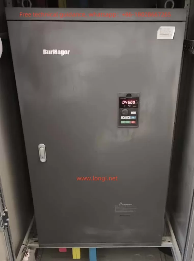
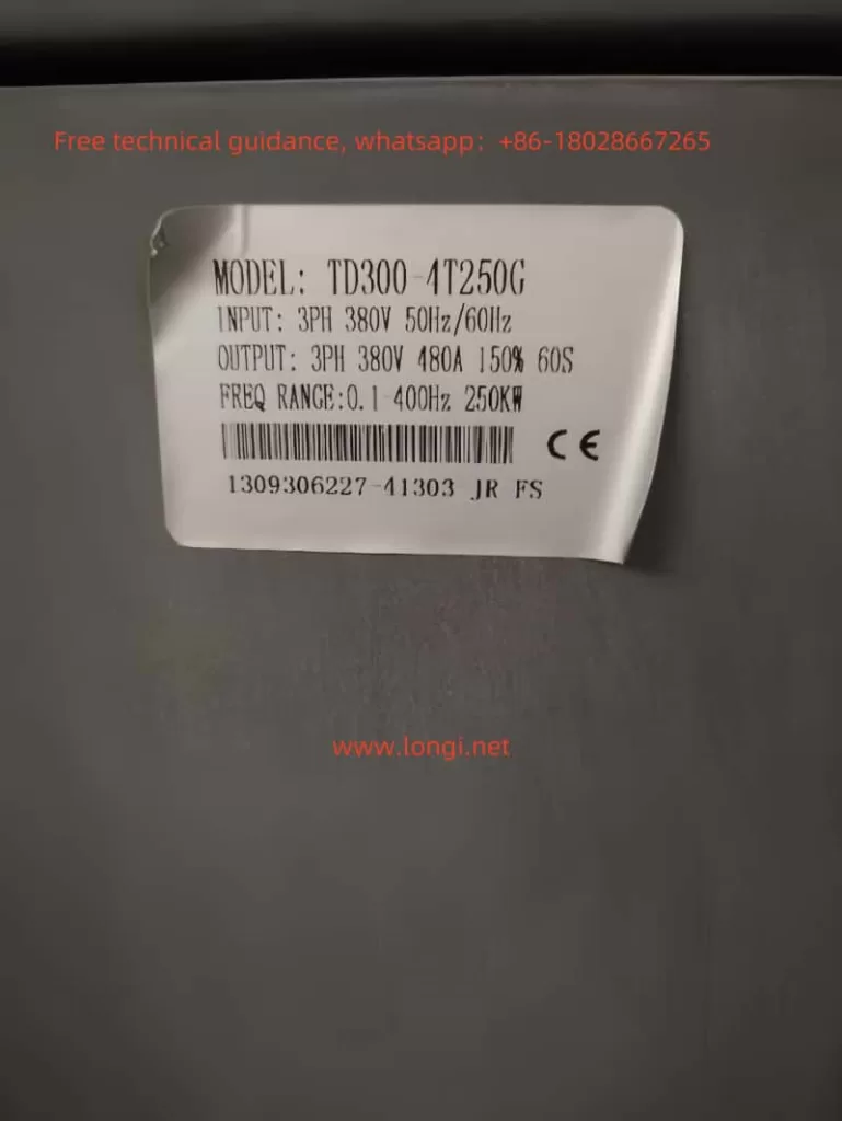
The Burmagor Inverter TD300 series is equipped with an intuitive and user-friendly operation panel, facilitating various settings and operations for users. The following is an introduction to the main functions of the operation panel:
1.1 Setting and Eliminating a Password
To ensure the security of inverter settings, the TD300 series inverter provides a password protection function. Users can restrict access to the inverter by setting a password. The method for setting a password is as follows:
- Enter the parameter setting interface.
- Locate the parameter related to password setting (please refer to the user manual for the specific parameter number).
- Input the desired password value.
To eliminate an already set password, simply reset the password parameter to its default value.
1.2 Setting Parameter Access Restrictions
In addition to password protection, the TD300 series inverter also supports restricting access to parameters. Users can lock specific parameters as needed to prevent unauthorized modifications. The method for setting parameter access restrictions is as follows:
- Enter the parameter setting interface.
- Locate the parameter related to parameter locking (such as F1.18).
- Set this parameter to the locked state.
1.3 Parameter Initialization Setting
When it is necessary to restore factory settings or resolve certain parameter setting errors, users can use the parameter initialization function. The specific operation steps are as follows:
- Enter the parameter setting interface.
- Locate the parameter related to parameter initialization (such as F1.17).
- Set this parameter to the initialization value (usually 8), and the inverter will return to its factory settings.
II. Terminal Forward/Reverse Start/Stop and External Potentiometer Speed Control
The TD300 series inverter supports terminal forward/reverse start/stop and external potentiometer speed control functions. The following are the steps and parameters required to implement these functions:
2.1 Terminal Forward/Reverse Start/Stop
To implement the terminal forward/reverse start/stop function, the following parameters need to be set:
- F1.02: Operation setting selection. Set to 1 (IO terminal), indicating that the operation command is given by the IO port.
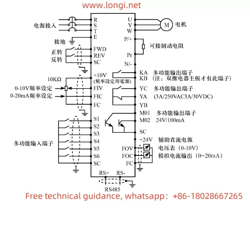
- F3.15-F3.16: Multi-function input terminal settings. Define the FWD terminal as forward (e.g., F3.15=6) and the REV terminal as reverse (e.g., F3.16=7).
In terms of wiring, external control signals need to be connected to the FWD and REV terminals, and the forward/reverse start/stop is achieved by controlling the on/off state of these two terminals.
2.2 External Potentiometer Speed Control
To implement the external potentiometer speed control function, the following parameter needs to be set:
- F1.01: Frequency setting selection. Set to 3 (keypad potentiometer setting mode), indicating that the operating frequency of the inverter is controlled by the potentiometer on the operator.
In terms of wiring, the output terminal of the external potentiometer needs to be connected between the +10V and FIV terminals of the inverter. By adjusting the knob of the potentiometer, the output frequency of the inverter can be changed, thereby achieving speed control.
III. Fault Codes and Their Handling
The TD300 series inverter has a comprehensive protection function. When a fault occurs, it displays the corresponding fault code. The following are some common fault codes, their meanings, and handling methods:
3.1 OC1/OC3 (Overcurrent during acceleration/operation)
- Meaning: There is an overcurrent phenomenon in the motor or output circuit.
- Handling methods:
- Check if the motor and output circuit are short-circuited or grounded.
- Extend the acceleration time (F1.07).
- Reduce the torque boost setting value (F2.08).
- Check if the grid voltage is stable.
3.2 OU1/OU3 (Overvoltage during acceleration/operation)
- Meaning: The output voltage of the inverter is too high.
- Handling methods:
- Extend the deceleration time (F1.08).
- Install a braking unit and braking resistor.
- Check if the power supply voltage is too high.
3.3 LU0/LU1/LU2/LU3 (Low voltage during standby/acceleration/deceleration/operation)
- Meaning: The power supply voltage is too low.
- Handling methods:
- Check if the power supply voltage is normal.
- Check if the power supply circuit has poor contact or is open-circuited.
3.4 OL0/OL1/OL2/OL3 (Overload during no operation/acceleration/deceleration/operation)
- Meaning: The motor load is too heavy.
- Handling methods:
- Reduce the load or increase the inverter capacity.
- Extend the acceleration time (F1.07).
- Check if the motor is stalled or seized.
IV. Conclusion
This article provides a detailed introduction to the operation panel functions of the Burmagor Inverter TD300 series, the setting methods for terminal forward/reverse start/stop and external potentiometer speed control, as well as common fault codes and their handling methods. By reasonably using these functions and settings, users can better control and maintain the inverter, ensuring stable operation of the equipment. At the same time, in the event of a fault, users can quickly resolve the issue based on the provided handling methods, reducing downtime and improving production efficiency.