I. Product Positioning & Technical Background
The Agilent VacIon Plus 20 is a mid-range ion pump with a nitrogen pumping speed of 20 L/s, making it a core model in the VacIon Plus series (which covers a full range from 0.4 to 1,000 L/s). It is designed for ultra-high vacuum (UHV) and extreme high vacuum (XHV) systems, with key applications including: academic research, high-energy physics (HEP) experiments, particle accelerators and synchrotron rings, scanning electron microscopy (SEM), imaging equipment, radiation therapy devices, and surface analysis instruments.
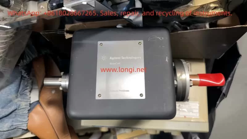
The official model numbers include 919-1114 (Diode, no magnet), 919-1115 (Diode, with ferrite magnet), 919-1144 (StarCell, no magnet), 919-1145 (StarCell, with ferrite magnet), and other variants. Users can select different pumping unit types, magnet configurations, and high-voltage feedthrough orientations based on actual pumping requirements.
II. Core Technical Principles
2.1 Diode Ion Pump Operating Mechanism
The diode ion pump core consists of a positively charged anode ring and a negatively charged titanium (Ti) cathode, both immersed in a magnetic field. When powered on, electrons collide with gas molecules in the plasma, generating positive ions. Light ions (e.g., H₂, He) accelerate toward the cathode, penetrate the Ti layer, and are buried and absorbed. Heavy ions strike the cathode, causing Ti sputtering. The sputtered Ti coats the inner surface of the anode ring, forming a fresh chemically active film that continuously traps active gases (H₂, N₂, O₂, etc.).
Key Limitation: The two-electrode structure cannot effectively trap noble gases (e.g., Ar), because noble gases do not chemically react with Ti. They must rely on physical sputtering for transport to the anode for pumping, which is far less efficient.
2.2 Triode / StarCell Ion Pump Operating Mechanism
Agilent’s proprietary StarCell pumping unit is a fundamental improvement over the traditional two-electrode design. It uses a star-shaped cathode geometry, which greatly increases the probability of noble gases being transported to the anode as energetic neutral particles, while the titanium cathode ensures high pumping speed for H₂. According to official technical documentation, StarCell is the only ion pump capable of handling large quantities of noble gases and hydrogen simultaneously, offering the highest pumping speed and capacity for methane (CH₄), argon (Ar), and helium (He).
Bottom line: if your system contains a significant proportion of noble gases or hydrogen, StarCell is the clearly superior choice over Diode.
2.3 Ion Pump as Vacuum Gauge
Because the ion current generated by an ion pump is proportional to pressure, in many applications (especially SEM), the VacIon Plus 20 can directly double as an ionization vacuum gauge — a capability that mechanical pumps like turbomolecular pumps do not have. However, this requires extremely low leakage current. Agilent achieves this through a patented anode design (reducing void volume, sharp edges, and metal “whiskers”), and the SEM version is further optimized for this parameter.
III. Key Performance Parameters
| Parameter | Value |
|---|---|
| Nitrogen pumping speed | 20 L/s (series range: 20–75 L/s) |
| Inlet flange | 2¾” ConFlat (NW 35 / CFF) |
| Maximum starting pressure | ≤ 5 × 10⁻² mbar |
| Ultimate pressure | < 1 × 10⁻¹¹ mbar |
| Maximum bake-out temperature | 350 °C (vacuum processing up to >400 °C) |
| Heater voltage | 100–120 V / 200–240 V, 140 W |
| Service life | 80,000 hours |
| Pump weight (no magnet) | 7 kg (15 lbs) |
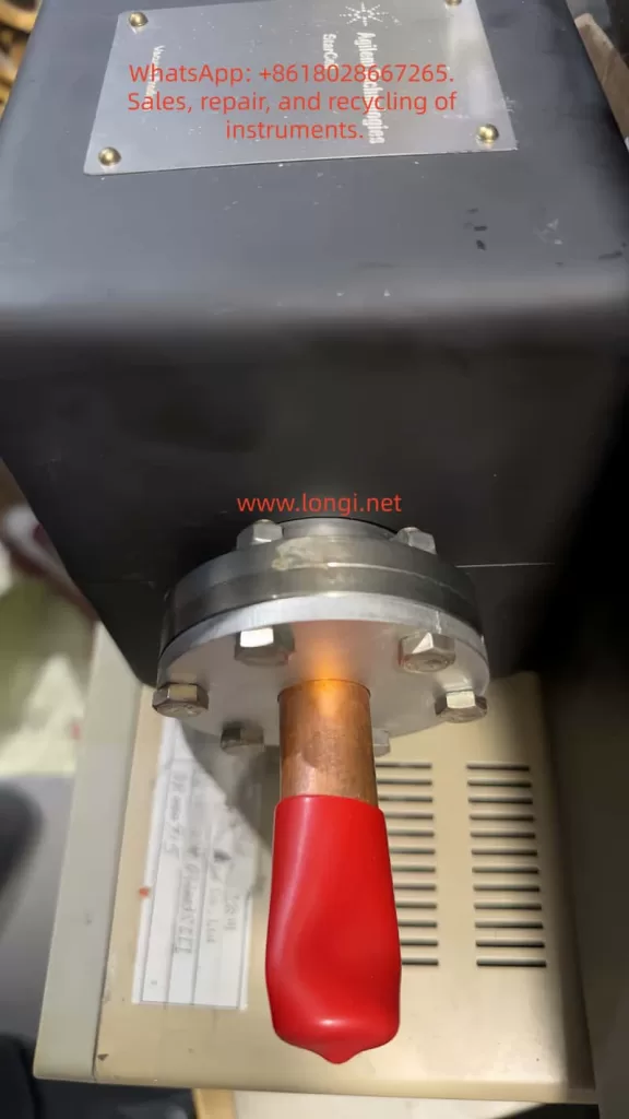
| High-voltage feedthrough options | Fischer, King, DESY, Varian, SHV 10kV (Safeconn) |
| Magnet options | Ferrite magnet, rare-earth magnet (NdFeB) |
Parameter Interpretation: The maximum starting pressure of ≤ 5 × 10⁻² mbar means this pump cannot be started from atmospheric pressure. A backing pump (e.g., scroll pump, diaphragm pump) must first reduce the system to the 10⁻² mbar range before the ion pump can be turned on. The ultimate pressure of < 10⁻¹¹ mbar is already in the XHV regime, sufficient for most surface analysis and particle physics experiments.
IV. Pre-Installation Preparation & System Integration
4.1 Cleanliness & Vacuum Integrity
The manual explicitly requires: the pump be vacuum-processed at >400 °C and clamped off under vacuum to ensure cleanliness and vacuum integrity before installation. This step is not a formality — any surface contamination becomes an outgassing source in UHV environments and will severely degrade ultimate pressure.
Practical Tips:
- Wipe the ConFlat flange face with anhydrous ethanol before installation; ensure no scratches or particles.
- The copper gasket (OFHC copper) must be new or annealed if reused; never use gaskets with deformation marks.
- Tighten bolts in a diagonal cross pattern in three passes, with torque per manual recommendations (typically ~20–25 N·m for a 2.75″ ConFlat flange).
4.2 Magnet Configuration Selection
| Configuration | Applicable Scenarios |
|---|---|
| No magnet (919-1114 / 919-1144) | System already has external magnets, or scenarios extremely sensitive to magnetic interference |
| Ferrite magnet (919-1115 / 919-1145) | General-purpose use, lower cost, moderate field strength |
| Rare-earth NdFeB magnet (919-1146 series) | Scenarios requiring stronger magnetic field for higher pumping speed; be aware of interference with nearby electronics |
4.3 High-Voltage Feedthrough Orientation
The ConFlat flange is rotatable, and the high-voltage feedthrough can be oriented in different directions (Fischer, SHV, etc.). Consider cable routing space, interference with other components, and whether optical baffles or other accessories are needed. The manual supports custom pump geometries and additional ports — specify these when ordering.
V. Startup Procedure
Step 1: Backing Pump Evacuation
Use a scroll pump or diaphragm pump to reduce system pressure to ≤ 5 × 10⁻² mbar. This is a hard requirement for ion pump startup — do not skip it.
Step 2: Power On the Ion Pump
Connect the heater power supply (100–120 V or 200–240 V, match to model), wait for the heater to stabilize (~5–10 minutes), then turn on the high-voltage supply.
Note: The manual does not specify an exact HV turn-on sequence, but per Agilent’s general ion pump operating guidelines, the filament (if equipped) should be turned on first, and the ion current should be allowed to stabilize before ramping to operating voltage. The Diode/StarCell versions of the VacIon Plus 20 typically do not require a filament — apply operating voltage directly.
Step 3: Monitor Ion Current & Pressure
After startup, the ion current should start high (corresponding to poorer vacuum) and gradually decrease, eventually stabilizing in the nA range. The vacuum gauge reading should continue to drop, ultimately reaching < 10⁻¹⁰ mbar.
Abnormal Condition Diagnosis:
- Ion current stays persistently high → possible leak or backing pump did not evacuate sufficiently.
- Ion current fluctuates abnormally → check HV power supply stability or whether the magnet is affected by external interference.
- Pressure cannot drop below 10⁻⁹ mbar → consider bake-out (350 °C, hours to days).
Step 4: Bake-Out (If Required)
If the system requires ultimate pressure better than 10⁻¹⁰ mbar, bake-out is necessary. The VacIon Plus 20 can withstand up to 350 °C (vacuum processing above 400 °C), but note:
- The ion pump should remain on during bake-out to continuously pump desorbed gases.
- Recommended ramp rate: ≤ 5 °C/min to avoid thermal shock causing flange leaks.
- After bake-out, cool naturally to room temperature before shutting down the ion pump.
VI. Daily Operations & Troubleshooting
6.1 Leakage Current Monitoring
Low leakage current is the foundation of stable VacIon Plus 20 operation. The manual notes that the SEM version features low leakage current and high stability, minimizing electronic interference. In daily operations, periodically record the ion pump’s ion current in the closed-valve state (i.e., leakage current). If leakage current rises significantly (exceeding several hundred nA), the anode or insulator may be contaminated — schedule maintenance.
6.2 Magnet Demagnetization Risk
Ferrite magnets may demagnetize at high temperatures. If the system requires frequent bake-outs above 300 °C, consider high-temperature-rated rare-earth magnets (NdFeB), but evaluate their magnetic interference with surrounding equipment. The manual offers shielded magnet options for use in strong-field environments.
6.3 Pumping Unit Replacement
Per Agilent’s official maintenance guide:
- Ion pumps ≥ 150 L/s can have their pumping units replaced individually (StarCell / Diode / Noble Diode).
- The VacIon Plus 20 is a smaller model; typically the entire pump body is replaced while retaining the magnet, to reduce maintenance cost.
Pumping Unit Comparison:
| Unit Type | Strong Gases | Weak Gases | Typical Application |
|---|---|---|---|
| Diode | N₂, H₂, O₂ | Ar, He | General UHV, electron microscopy |
| Noble Diode | Mixed gases, H₂ | Pure noble gases | Particle accelerators, synchrotron rings |
| StarCell | Ar, He, CH₄, H₂ | — | Systems with high noble gas loads |
6.4 Common Faults & Solutions
| Symptom | Possible Cause | Solution |
|---|---|---|
| Cannot start (HV will not establish) | Backing pressure > 5×10⁻² mbar | Re-evacuate with backing pump |
| Abnormally high ion current | System leak / outgassing source | Helium leak check, inspect flange seals |
| Ultimate pressure not reaching spec | Insufficient bake-out / aging pumping unit | Extend bake-out time, consider pump replacement |
| Unstable pressure reading | Excessive leakage current / external EMI | Check grounding, evaluate need for shielded magnet |
VII. Shutdown & Long-Term Storage
7.1 Normal Shutdown
- Turn off the ion pump high-voltage supply.
- Keep the heater on for an additional 10–15 minutes (to purge residual gas from the pump body).
- Turn off the heater power supply.
- Turn off the backing pump.
- Backfill with dry nitrogen or argon to atmospheric pressure (to prevent moisture condensation inside the pump).
7.2 Long-Term Storage (Exceeding 1 Week)
The manual recommends filling the pump with methanol or inert gas before long-term storage to prevent seal drying. Procedure: flush the system with methanol for 30 minutes, reduce flow to zero before shutdown, and keep the pump filled with methanol. To restart, first use the backing pump to remove methanol vapor, then follow the normal ion pump startup procedure.
VIII. Model Selection Decision Tree
Faced with model numbers like 919-1114, 919-1115, 919-1144, 919-1145, follow this logic:
- Does the system contain large amounts of noble gases (Ar, He)?
- Yes → Choose StarCell (919-1144 / 919-1145)
- No → Next step
- Is mixed-gas pumping speed also needed?
- Yes → Choose Noble Diode (if available)
- No → Choose Diode (919-1114 / 919-1115)
- Does the system already have external magnets?
- Yes → Choose no-magnet version (save cost)
- No → Choose ferrite or rare-earth magnet based on magnetic interference tolerance
- Is there a special requirement for HV feedthrough orientation?
- Yes → Choose the corresponding custom model (e.g., 919-1145M021 = SHV feedthrough, 919-1145M022 = 90° feedthrough)
- No → Standard Fischer feedthrough is sufficient
IX. Summary
The VacIon Plus 20 is not a “plug-and-play” device. It is a complete vacuum solution that must work in concert with a backing pump, vacuum gauge, and bake-out system. Every parameter in the manual — from the 5 × 10⁻² mbar maximum starting pressure to the 350 °C bake-out limit, from StarCell’s noble gas handling capability to the SEM version’s low-leakage-current design — represents an engineering constraint forged over decades of UHV applications.
Understanding these constraints matters more than memorizing the steps. Because when something goes wrong, what actually helps you diagnose the problem is not what page of the manual says what — it’s whether you truly understand the ion pump’s physical behavior at every pressure range and in every gas environment.