I. Operation Panel Functions and Basic Settings
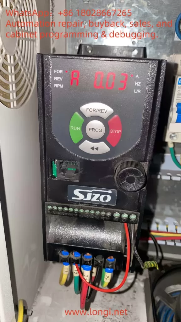
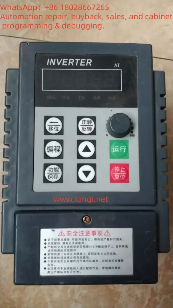
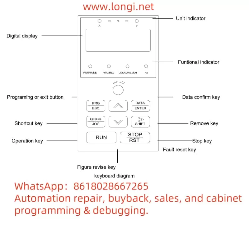
1. Operation Panel Function Introduction
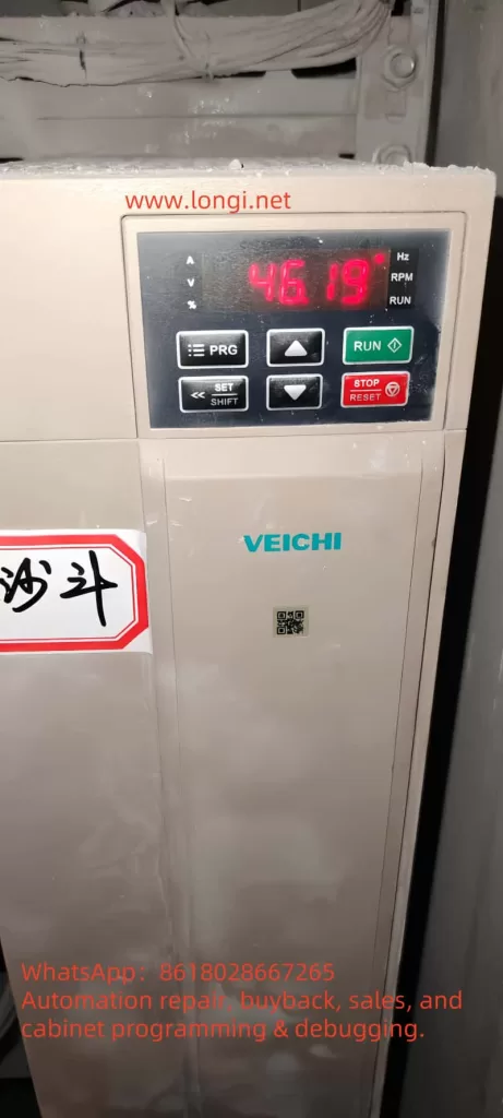
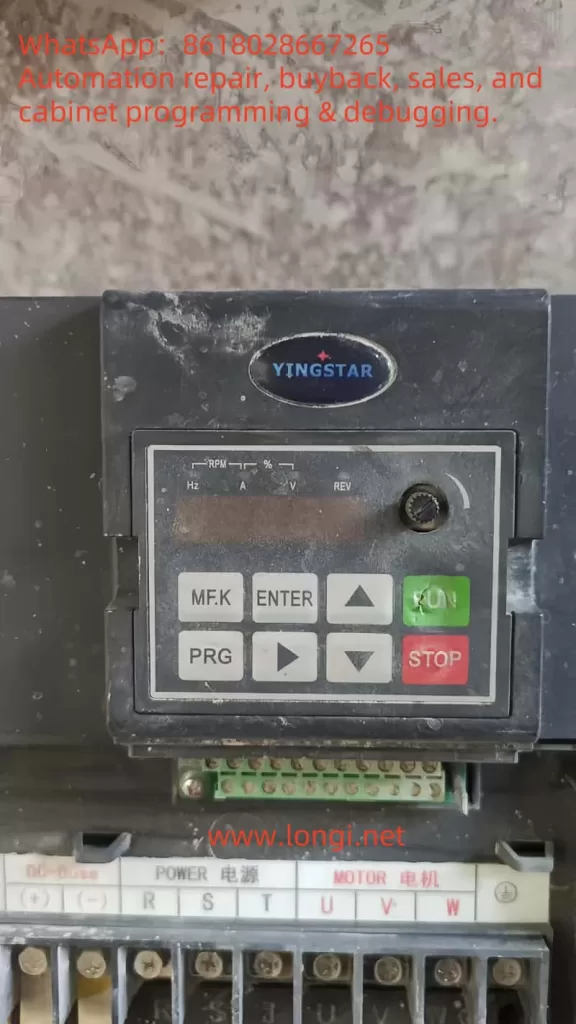
- Key Functions:
- RUN Key: Starts the VFD operation; requires configuration of the operation command channel.
- STOP/RESET Key: Stops the device during operation or resets alarms during fault states.
- PRG Key: Enters the parameter editing menu, supporting three-level menu navigation (Function Group → Function Code → Parameter Value).
- Direction Keys (▲/▼): Switches between displayed parameters or adjusts values, supporting cyclic selection and bit modification.
- FUN Key: Can be customized for jog operation or forward/reverse switching (configured via F7.03).
- Display Area:
- 5-Digit LED Display: Shows operating frequency, fault codes, parameter values, etc.
- Status Indicators: Include operating status (RUN/TUNE), forward/reverse (FWD/REV), local/remote control (LOCAL/REMOTE), and fault (TRIP) indicators.
2. Restoring Factory Default Settings
- Steps:
- Navigate to Function Group F0 → Select F0.13 (Function Parameter Restore).
- Set to 1 (Restore Factory Defaults) → Press the confirmation key (ENT) to save.
- Note: After restoration, key parameters (e.g., motor nameplate data, control mode) must be reconfigured.
3. Password Setup and Access Restrictions
- Setting Password: Input a 4-digit number (range 0~65535) via F7.00 (User Password); non-zero values take effect.
- Removing Password: Set F7.00 to 0 or restore factory defaults.
- Parameter Access Restrictions:
- A valid password is required to enter editing mode (display “PASS” before input).
- Some parameters (marked with “-“) are manufacturer-specific and cannot be modified by users.
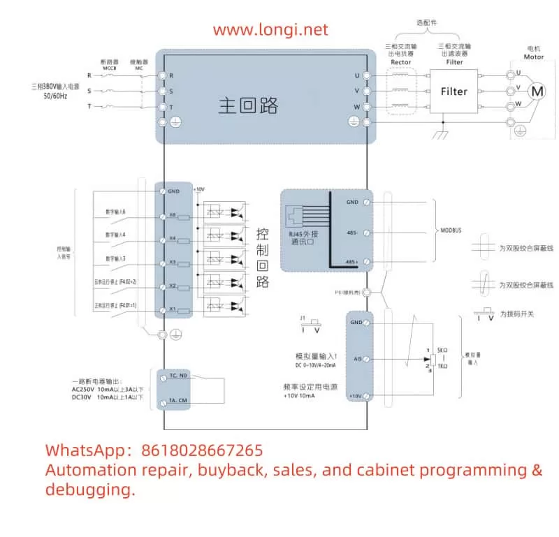
II. External Terminal Control and Speed Adjustment Settings
1. External Terminal Forward/Reverse Control
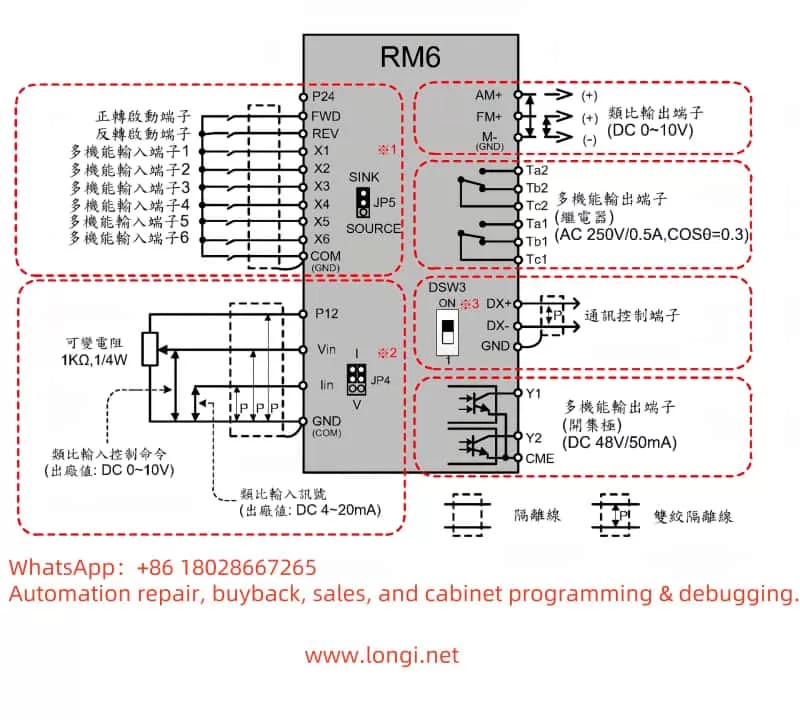
- Terminal Connections:
- Forward Terminal: X1 (default function code F5.04=1).
- Reverse Terminal: X2 (default function code F5.05=2).
- Common Terminal: COM.
- Parameter Settings:
- Set F0.01 (Operation Command Channel) to 1 (Terminal Command Channel).
- Configure F5.07 (Terminal Control Mode):
- 0 (Two-Wire Control): X1 for forward, X2 for reverse; both closed stops the drive.
- 1 (Three-Wire Control): Requires an additional terminal as an enable signal (e.g., configure X3 as “Three-Wire Operation Control”).
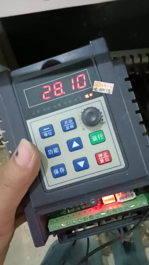
2. External Potentiometer Speed Adjustment
- Terminal Connections:
- Potentiometer Signal Input: VS1 (0~10V) or VS2 (0~10V/4~20mA, selected via jumper).
- Signal Ground: GND.
- Parameter Settings:
- Set F0.03 (Frequency Command Selection) to 2 (Analog VS1) or 3 (Analog VS2).
- Calibrate Input Range (Optional): Adjust F5.09~F5.12 (VS1 Upper/Lower Limit Corresponding Values) to ensure 0~10V corresponds to 0%~100% frequency.
- For current signals (4~20mA), switch VS2 jumper to current mode (JP2 position).
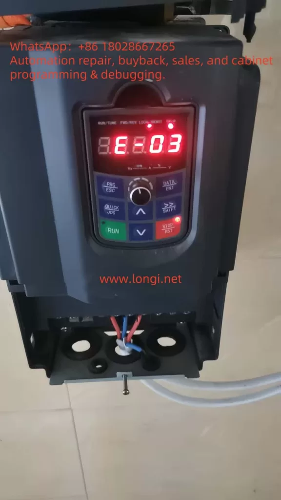
III. E-03 Fault Analysis and Solution
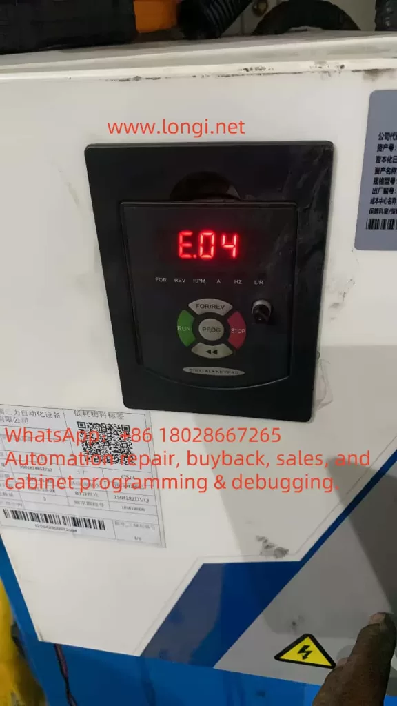
1. Fault Definition and Symptoms
- E-03 Fault: Overcurrent during constant-speed operation, triggering protective shutdown. The LED display shows “E-03” and flashes.
2. Possible Causes
- Load Sudden Change: Mechanical jamming, abnormal drive system (e.g., gear damage).
- Power Supply Abnormality: Input voltage fluctuations or instantaneous drops.
- Improper Parameter Configuration: Motor parameters (Group F2) do not match actual values, or carrier frequency (F0.11) is set too high.
- Hardware Issues: Abnormal current detection circuit, aged IGBT module.
3. Solution Steps
- Step 1: Check Load and Mechanical System
- Disconnect the motor from the load and test under no-load conditions to check if the fault persists.
- Inspect couplings and bearings for jamming; eliminate mechanical abnormalities.
- Step 2: Optimize Parameter Configuration
- Adjust F0.11 (Carrier Frequency): Reduce the carrier frequency (e.g., from 8kHz to 4kHz) to reduce switching losses.
- Calibrate Group F2 (Motor Parameters): Perform motor self-learning (F0.12=1 or 2) to ensure accurate stator resistance and inductance values.
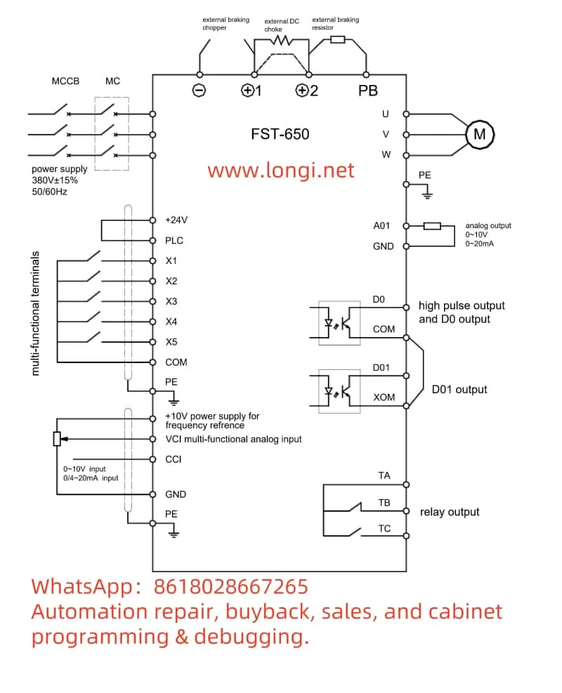
- Step 3: Check Power Supply and Hardware
- Measure three-phase input voltage to ensure balance deviation <15%.
- Detect DC bus voltage; if abnormal fluctuations occur, install an input reactor.
- Troubleshoot current sensor (Hall element) or drive circuit faults; replace modules if necessary.
4. Preventive Measures
- Regularly clean the cooling fan to ensure the inverter module temperature (F7.09) <85°C.
- Enable F8.07 (Automatic Current Limiting Function) and set the current limiting level (F8.07=150%) to suppress sudden overcurrents.
IV. Conclusion
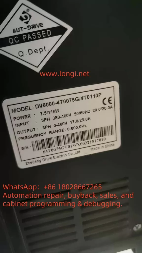
The AUT-DRIVE DV6000 VFD offers flexible parameter configuration and terminal control functions to meet complex industrial requirements. Operators must strictly follow the manual instructions, perform regular maintenance, and record operational data. For E-03 faults, systematically troubleshoot load, power supply, parameter, and hardware issues, combined with function code adjustments and mechanical maintenance, to ensure stable device operation. Password protection and parameter access restrictions further enhance equipment management security.